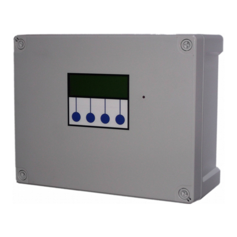
3P Technik TC320 User manual

3P Technik
TC320/330/340 Tank Level
Controller
Installation and Operating Manual
TC Series Controller v1.30 www.3ptechik.co.uk 09-August-2017 Page 1 o 28

Table o Contents
Safety........................................................................................................................................................3
Installation................................................................................................................................................3
Included Components....................................................................................................................................3
Layout.............................................................................................................................................................4
Control Panel Mounting.................................................................................................................................6
Mains Power Connection...............................................................................................................................6
Output Power Connections............................................................................................................................7
Switch Input Connections..............................................................................................................................7
Tank Level Sensor Connections......................................................................................................................7
BMS connection.............................................................................................................................................7
Troubleshooting........................................................................................................................................7
Fuse Listing.....................................................................................................................................................9
Inputs (le t to right) – Con1...........................................................................................................................9
Pressure Sensor Inputs (le t to right).............................................................................................................9
BMS Output..................................................................................................................................................10
Output Control Outputs (le t to right).........................................................................................................10
Upgrades and Modifications....................................................................................................................10
Specifications..........................................................................................................................................11
Control Panel................................................................................................................................................11
Tank Level Sensor.........................................................................................................................................11
Switched Outputs (pump/solenoid/valve control)......................................................................................11
Operation................................................................................................................................................12
Description o Operation.............................................................................................................................12
Control Panel Operations.............................................................................................................................13
Menus and Functions..............................................................................................................................13
Water Level Display.................................................................................................................................14
Accessing the Menu Options...................................................................................................................14
Status Screen...........................................................................................................................................14
Main Menu..............................................................................................................................................14
Setup Menu (Menu>Setup)................................................................................................................14
Virtual Output Setup (Menu>Setup>Virtual).................................................................................14
Output Setup (Menu>Setup>Outputs)..........................................................................................15
Main Functions..........................................................................................................................15
Virtual Input Selection..............................................................................................................15
Levels.........................................................................................................................................15
Duty Cycle..................................................................................................................................15
Output Con iguration Examples................................................................................................16
Tank Alarms (Menu>Setup>Alarms)..............................................................................................17
Fault Diagnosis........................................................................................................................................17
Diagnostic Menu (Menu>Diags).........................................................................................................17
Input Options (Menu>Diags>Inputs).............................................................................................17
View Inputs (Menu>Diags>Inputs>View Input)........................................................................17
Adjust Probe Stability (Menu>Diags>Inputs>Adjust Probe Stability).......................................18
Activate Outputs (Menu>Diags>Outputs).....................................................................................18
View Logged Fault Codes (Menu>Diags>Faults)............................................................................19
TC Series Fault Codes (all models)......................................................................................................19
Clear Logged Fault Codes (Menu>Diags>Faults>Clear)............................................................21
Run..........................................................................................................................................................21
Stop.........................................................................................................................................................21
Menu (Stop>Menu)............................................................................................................................21
TC Series Controller v1.30 www.3ptechik.co.uk 09-August-2017 Page 2 o 28

Wipe Con iguration (Stop>Wipe Con ig)............................................................................................22
Restart (Stop>Restart)........................................................................................................................22
Troubleshooting...........................................................................................................................................22
Fuse Listing..............................................................................................................................................23
Inputs (le t to right) – Con1.....................................................................................................................24
Pressure Sensor Inputs (le t to right)......................................................................................................26
BMS Output (con5)..................................................................................................................................26
Outputs (le t to right)..............................................................................................................................26
Upgrades and Modifications....................................................................................................................27
Specifications..........................................................................................................................................2
Control Panel................................................................................................................................................28
Tank Level Sensor.........................................................................................................................................28
Switched Outputs (pump/solenoid control)................................................................................................28
Sa ety
Mains Voltage – There are exposed electrical conductors inside this appliance. This appliance must be
installed and serviced by a competent electricical technician to the current requirements o BS7671 and
IEEE recommendations.
Be ore servicing this appliance, normal sa e isolation procedures should be implemented.
Do not touch the PCB while energised, it carries mains voltage.
Do not touch any connection terminals while energised.
Do not attempt to service this item when wet, or in a wet or high humidity environment.
I the housing o the control panel becomes damaged, you must shut down and securely isolate this
appliance immediately.
You must connect this appliance to a grounded 3 wire supply, protected by suitable overload protection.
Connected pumps and solenoids are earthed via the control panel, and may otherwise become live.
I the power cables are damaged, either to o rom the controller then shut down and isolate this apliance.
The combined loading o pumps, etc. connected t this appliance must not exceed 20A using the supplied
mains lex. Contact the manu acturer or advice i you need to exceed this rating.
Do not attempt to repair any part o the circuit board. Re er to the manu acturer or advice.
Installation
Included Components
1 x Control Panel
1 x 2m Mains Flex 2.5mm
TC Series Controller v1.30 www.3ptechik.co.uk 09-August-2017 Page 3 o 28

Cable Glands (qty depending on model)
1 x Pressure transmitter with 20m cable
Optional - 2nd Pressure transmitter with 20m cable
Layout
Unlike a pressure based controller, the 3P TC Series Tank Controller does not contain any plumbing. This
means you can install the control panel anywhere you wish within the building.
You will need to consider the ollowing constraints,
The control panel cannot be mounted outside, it is not weather resistant (although can be made weather
resistant – call us or advice)
Voltage drop will a ect the cable size needed to take power to your pumps. Over very long runs, you may
ind it more economical to install contactors near to the pumps, allowing you to control the pumps with a
sensible cable size. It is strongly recommended that you calculate voltage drop or cable runs in excess o
20m. Failure to do so may result in aulty operation, cable overheating, conductor migration, and risk o
ire. The same caution applies to solenoid valves, although the current draw is usually so small that only
extreme distances are likely to present a problem.
Also note that all control cabling (sensor and switch wiring) beyond a ew metres and installed in
electrically noisy environments may need to be shielded to avoid alse switch detection or unstable level
readings.
Note – it is recommended that you earth the shielding on cables (where present) to an earth terminal
within the controller. Do not earth to DC 0v as the DC power supply is isolated and will not function as a
ground.
Do not install control cabling next to mains power cables, particularly over long distances. Adequate
separation rom power cables will reduce potential problems. Where control cabling must cross mains
wiring it should be done at right angles and kept to a minimum.
We do not make any recommendation as to the speci ic cable or layout to be used. It is the responsibility o
the installer to install control cabling appropriately giving consideration to length and proximity to
electromagnetic noise.
It is expected that the installer is suitably competent with regard to electrical installation, and the
provisions o and testing in accordance with the current regulations in orce in your area. It is also expected
that the installer is competent to install, validate and resolve any issues with regard to control cabling.
In the event o unresolved inter erence to switch inputs, it is possible to create a separate powered sensor
circuit at low voltage operating relays near to the control panel to act as inputs. This will have much higher
immunity to parasitic voltages than the transistor based inputs on the control panel.
Most instability o the level sensor caused either by inter erence or turbulence in the water itsel can be
compensated in so tware by adjustment o the probe stability setting.
Pressure transmitter cable is o a special type incorporating a vent tube to equalise the pressure within the
transmitter to atmospheric pressure (3P part no. IRVENT or IRVENTX depending on type). The vent should
TC Series Controller v1.30 www.3ptechik.co.uk 09-August-2017 Page 4 o 28

terminate in a dry location. I not then it must be extended in vented cable to a suitable location, or
terminated in a sealed box with moisture resistant breather plug.
TC Series Controller v1.30 www.3ptechik.co.uk 09-August-2017 Page 5 o 28

Control Panel Mounting
Having selected a suitable location, unlock the 4 locking screws on the corners o the ront cover and
withdraw the ront panel. The LCD display, buttons and alarm LED are connected to the PCB. Remove and
replug these cables a terwards i necessary in accordance with the diagram.
The 4 screw mounting holes are located on the main enclosure in recesses adjacent to the ront panel
mounting holes. Mark drilling points on the wall accordingly. Withdraw the casing rom the wall and drill
holes appropriate or your selected ixings.
Mains Power Connection
The power supply to the control panel enters via a cable gland on the bottom right o the housing. Insert
the cable, connect to the incoming power terminal on the right o the PCB, and tighten the cable gland.
TC Series Controller v1.30 www.3ptechik.co.uk 09-August-2017 Page 6 o 28

Output Power Connections
Pumps, solenoids, motirised vbalves etc. are powered rom the rightmost green terminals on the lower
right o the PCB. From le t to right terminals 2,3,4 and 5 supply Outputs 1,2,3 and 4 (ternimal 1 is the BMS
output). The terminal blocks are socketed and can be withdrawn rom the PCB or ease o access.
Switch Input Connections
These inputs are used to connect switches, rain sensors or other control devices into the panel, and are
used alongside the level probes to decide when to switch an output on or o .
They are connected to the 10 pin plug on the bottom le t o the PCB marked “inputs” using the shielded
cable provided, in the ollowing order.
Input 1 Pins 1 and 2
Input 2 Pins 3 and 4
Input 3 Pins 5 and 6
Input 4 Pins 7 and 8
Input 5 Pins 9 and 10
Polarity is unimportant.
Note – If cables need to be routed into the controller other than with the cables glands fitted ensure
they enter the bottom of the casing and do not cross over the circuit board. If necessary use trunking to
route cables appropriately.
Tank Level Sensor Connections
Connect the tank level sensor(s) to con3 and also con4 i you have a 2nd tank level sensor.
White wire to the le tmost pin o the 2 pin connector
Brown wire to the rightmost pin o the 2 pin connector
The level sensor connected to con3 is Tank 1
The level sensor connected to con4 is Tank 2 (i itted)
Note – these inputs sense current in milliamps don't test them by shorting them out the input circuit will
be damaged and you will have to send the board back for repair.
BMS connection
The BMS connection provides a non-voltage relay capable o switching any 230V source up to 10A. Three
contacts are provided, Common, NO and NC. Connect your live conductor rom the BMS system to
Common, and output will be switched to NC in the absence o an alarm condition, switching to NO upon an
alarm.
Troubleshooting
Re er to the Sa ety instructions. No electrical works should be carried out other than by an appropriately
quali ied Electrician. Permits to work may be required at local site conditions. I in any doubt, consult your
system supplier.
TC Series Controller v1.30 www.3ptechik.co.uk 09-August-2017 Page 7 o 28

Problem Probable Cause Solutions
No Power – controller
dead – no backlight on
LCD
No power supply rom
distribution board
Fuse ailed
PCB damaged
Check 240 vac 50hz supply at
power input terminals.
Check Fuse F1
Replace PCB, contact
manu acturer.
Backlight on – no
display – no operation
CPU chip missing
CPU chip badly inserted or
bent pins
CPU chip wrong way round
CPU chip aulty
PCB damaged
Insert CPU
Insert CPU correctly or replace i
necessary
Remove and re-insert correctly
Replace CPU
Replace PCB, contact
manu acturer.
Controller Frozen –
operates normally but
keypad unresponsive
Keypad not connected or
connected wrong
Check connection, try reversing
connector direction
Controller Frozen –
does not operate
normally
CPU or oscillator damaged Replace CPU, i no success
replace PCB
Switch input appears
not to unction
Not connected
Cable damaged
Float switch not
constrained properly
Float aulty
Check connection to control
panel
Test continuity, replace i
necessary
Tie loat in tank such that it
switches up/down around
switch point
Replace
Tank level sensor does
not unction
Not connected
Connected wrongly
Sensor aulty
Input circuit aulty
Check wiring to controller
Check wiring polarity and
correct i needed
Test with loop calibrator,
replace sensor i necessary
Test with loop calibrator,
replace PCB i necessary
Tank Level sensor
reads incorrectly
Cable vent tube blocked or
sealed
Ensure vented section o cable
terminates to atmospheric
pressure
TC Series Controller v1.30 www.3ptechik.co.uk 09-August-2017 Page 8 o 28

Wrong sensor speci ication
installed
Sensor aulty
Replace with original OEM spec
part
Test with loop calibrator,
replace i necessary
Header tank over low
detected (error 10)
Sensor installed wrong way
up
Sensor installed too low
High level sensor ailure
causes over low
Solenoid stuck open
Check orientation, toggle should
hang downward.
Relocate above other sensors
Test and replace sensor
Isolate power, test and replace
solenoid
Note – References to loop calibrator refer to a current loop calibrator 4-20mA NOT a loop impedance
test.
Fuse Listing
F1 – 500mA 20mm quickblow
F2 – 1A 20mm glass passivated
F3 – 10A 20mm glass passivated
F4 – 10A 20mm glass passivated
F5 – 10A 20mm glass passivated
F6 – 10A 20mm glass passivated
Inputs (le t to right) – Con1
1 – Switch 1
2 – Switch 2
3 – Switch 3
4 – Switch 4
5 – Switch 5
Pressure Sensor Inputs (le t to right)
Con3 (le t) – Tank 1 Level Sensor
Con4 (right) – Tank 2 Level Sensor
TC Series Controller v1.30 www.3ptechik.co.uk 09-August-2017 Page 9 o 28

BMS Output
Type – Non contact relay
Terminals – Common, Normally Open, Normally Closed
Power Rating max 10A 230Vac
Output Control Outputs (le t to right)
1 – Output 1
2 – Output 2
3 – Output 3
4 – Output 4
Upgrades and Modi ications
The ollowing parts o the system can be upgraded at any time without any modi ication to the control
panel.
Replacement/upgrade o pump(s)
Replacement/upgrade o solenoid(s)
Note – there is no need to reprogram or adjust the control panel settings when replacing a pump with
one of a different power output or consumption. Diagnostic functions are not dependent on current
monitoring.
Installation o 3 phase pump(s) via external contactor/relay.
So tware upgrade by either on-site reprogramming, or by CPU replacement. Reprogramming is unlikely to
ever be necessary, but is provided or to allow or custom so tware to be retro itted to the control panel. It
is carried out by an approved engineer via an on-board programming port, or via replacement o the CPU.
The CPU is socketed in a 40pin DIP socket or ease o replacement. The CPU is a
When replacing the CPU, always use a proper DIP Extraction Tool, and ollow the instruction provided with
the replacement CPU.
TC Series Controller v1.30 www.3ptechik.co.uk 09-August-2017 Page 10 o 28

Speci ications
Control Panel
Dimensions 240mm x 190mm x 110mm
Supply Voltage 230-240 Vac 50Hz
Power Consumption 7w (Control Panel Only)
Operating temperature range 0 to 40 degrees celsius
Ingress protection IP66 (IP68 available on request)
Tank Level Sensor
Type Pressure Transmitter 2 wire
Measurement Range 0-0.6 bar
Input 8 to 30 Vdc
Output 4-20mA
Switched Outputs (pump/solenoid/valve control)
Voltage 230-240vac 50hz (exact voltage as supply
voltage)
Current 10A (peak 16A)
TC Series Controller v1.30 www.3ptechik.co.uk 09-August-2017 Page 11 o 28

Operation
Description o Operation
The 3P TC Series Tank Controller is a luid level control system which maintains the water level in a tank
between 2 set points (adjustable) by switching on pumps, solenoid valves, or any other connected devices
to ill or drain the tank as needed. It is a microprocessor based unit and senses water depth using a piezo
electric pressure sensor.
This type o solution provides vast improvements in reliability when compared with traditional panel built
systems based on loat switches, along with reduced installation time, easy recon iguration, reduced
maintenance, and smaller space requirements within the plant room.
The upper and lower set points and unction o devices within the tank are easily set rom the control panel
without the need to access the rainwater tank.
Control o attached devices is provided via direct mains voltage outputs rom the control panel in single
phase, operating as necessary within the level set points speci ied by the user. Pumps, solenoids,
motorised valves and sluices can all be controlled automatically to add or remove luid to achieve the
desired level. Multiple appliances can be used within the same tank.
Contactors or relays can be used to allow control o 3 phase, or low voltage devices.
Outputs can be assigned as Fill or Drain types, and are each set a level range between which to operate.
Each output can be assigned to one probe, and up to 5 switched inputs and 2 virtual inputs to provide
urther quali ication or activation. For example, a pump could be assigned to drain a tank upon reaching a
certain level only i a reed switch at the destination tank reports it as not being already ull, or perhaps to
supply water to an outlet only i a pressure switch on that line shows low pressure.
Virtual I/O consists o inputs and outputs that don't physically exist, you can't connect wires to them as
there are no terminals, but a virtual output is connected logically to a corresponding virtual input. In act,
the output and input are just two ways o visualizing the same object in the so tware. By setting a virtual
output to trigger on certain levels and inputs rom one tank and then using it as an input or the other, the
behaviors o both tanks can be made interdependent.
For attenuation systems, the use o a pressure based sensor allows or a very wide band o operation
between cut-in and cut-out levels. The ability to operate di erent pumps with di erent purposes
independently in the same tank easily allows you to con igure combined harvesting/attenuation systems,
or add a high level pumped over low without additional control equipment.
TC Series Controller v1.30 www.3ptechik.co.uk 09-August-2017 Page 12 o 28

Control Panel Operations
Menus and Functions
Upon irst applying power, the LCD panel will display a startup logo ollowed by automatic setting o
de ault parameters. In this state all outputs are unassigned, the panel will show the water level or tanks 1
and 2. I a probe or either tank is not connected it will show as empty.
Water level is displayed in cm, unlike other versions o this panel which read a percentage the TC Series
controller is concerned only with absolute levels, not relative capacity.
TC Series Controller v1.30 www.3ptechik.co.uk 09-August-2017 Page 13 o 28

Water Level Display
The current water level or each tank will be shown in cm. Where no probe is attached the corresponding
tank level will not be shown.
Note that i an output has been set to use a probe which is not present, a ault will be registered
accordingly as that probe will be assumed to be aulty, or unintentionally disconnected. I no outputs are
set to use a particular probe, then it's absence will not be registered as a ault.
Accessing the Menu Options
The last line o the display always shows up to our menu options, which can be selected by pressing one o
the our corresponding buttons beneath the display. The menu options displayed will change as you enter
di erent areas o the so tware.
Status Screen
This is the screen that will show during normal operation, and is where the system de aults to a ter power-
on. While this screen is showing the system operates as normal, water level displays are continuously
updated and any outputs which have been con igured will operate as needed.
Note that i MENU or STOP are pressed, all operation will halt until the user returns to this main status
screen. The operator must there ore decide whether halting the system or con iguration is appropriate
and or how long.
Main Menu
3 options are available,
Setup – allows the operator to con igure the operation o the system.
Diags (Diagnostics) – Allows the user to review and clear any logged aults rom the system, test the status
o all inputs and test all outputs.
Run – returns to the main status screen and resumes operation.
Setup Menu (Menu>Setup)
4 options are available
Virtual – sets the conditions that will operate each virtual output.
Outputs – sets the conditions that will operate each physical output.
Alarms – sets high and low level alarm levels or each tank which will trigger the BMS output.
Exits – returns to the Main Menu.
Virtual Output Setup (Menu>Setup>Virtual)
Unless you are controlling 2 tanks and want an output to operate depending on the conditions in both
tanks this setting can be skipped.
3 options are available :-
I/O 1 – sets the range or probe 1 – currently this unction is unused.
TC Series Controller v1.30 www.3ptechik.co.uk 09-August-2017 Page 14 o 28

I/O 2 – sets the range or probe 2 – currently this unction is unused.
Stability – sets the sensitivity o the probe, used to compensate or alse changes in level reading caused by
incorrect probe location or turbulence during illing.
Exit – returns to the Setup Menu.
Output Setup (Menu>Setup>Outputs)
This menu allows you to select one o 4 outputs to con igure. Once selected 2 screens will be shown, the
irst allowing the output to be set to either ill o drain the tank, use either probe and any combination o 5
switched inputs. The second screen will allow the setting o the minimum and maximum levels in the tank
which it will maintain.
Main Functions
The options on the irst screen are as ollows
Button 1 will select either O , Fill, or Drain. A solenoid illing a storage tank or example would be set as a
Fill device, wheras a drainage pump would be a Drain device.
Button 2 Selects which probe, and hence which tank the output will be operating with. This does not mean
the device has to be in that tank but usually this will be the case. A trans er pump in tank 1 pumping to
tank 2 could be set as either a Drain type device operating on probe 1, or a Fill type device operating on
probe 2, whichever is most appropriate.
Button 3 selects one or more o 5 switched inputs which must be closed in order or the output to operate.
This condition is in addition to the trigger levels being reached.
Button 4 takes you to the virtual input selection screen.
Virtual Input Selection
, where in addition to the input switches sleected previously you can also select either or both o the 2
virtual inputs (these are triggered by the virtual outputs). Button 1 selects these inputs and button 4 moves
on to the next screen to set the operating levels or this output.
Levels
In this screen buttons 1 and 2 adjust the level up and down, and button 3 selects adjustment o either the
minimum or maximum level. The minimum and maximum levels cannot be set closer than 3cm rom each
other, nor can they overlap. I you try to set the minimum level as high as the maximum, the maximum will
increase itsel . I you try to set the maximum level down to the minimum level it will stop 3cm above that
level. Button 4 then proceeds to the Duty Cycle selection screen.
Duty Cycle
Here you are able to select the duty cycle or the output you are con iguring. Each output can operate rom
1 to 100% duty cycle (de ault setting is 100%) operating in 10 minute periods. So a duty cycle o 30% would
result in the output, when activated, running or 3 minutes then pausing or 7 minutes every 10 minutes.
TC Series Controller v1.30 www.3ptechik.co.uk 09-August-2017 Page 15 o 28

When used in conjunction with the known low rate o a pump or valve, duty cycling can be used to reduce
the low rate o an output to a speci ied maximum.
Output Con iguration Examples
Example 1 - A solenoid maintaining a 2 metre deep storage tank 1 with mains water
Output 1
Type Probe Switch
Fill 1 none Next
Output 1 Levels–
Min Max
172cm 1 8cm
- + Min Exit
Explanation – Fill tank 1 when the water drops to 172cm, stop when it reaches 198cm. The solenoid would
not operate until the level drops to 172cm or less, but once activated will not stop until the level reaches
it's high set point o 198cm.
Example 2 - 2 drainage pumps pumping sur ace water rom a sump tank
Output 1
Type Probe Switch
Drain 1 none Next
Output 1 Levels–
Min Max
52cm 75cm
- + Min Exit
Output 2
Type Probe Switch
Drain 1 none Next
Output 2 Levels–
Min Max
52cm 0cm
- + Min Exit
Explanation – the pump on output 1 will activate when the level in tank 1 reaches or exceeds 75cm and will
stop once the level is reduced to 52cm. I the level increases beyond the capacity o this pump, the pump
on output 2 will activate at 90cm, also not stopping until the level reduces to 52cm. This is Duty Assist/Duty
Standby without alternation.
Example 3 - A direct eed rainwater harvester, using a solenoid on output 1 or mains water back up, a
supply pump on output 2 and a pressure switch on switched input 1 to signal the pump to supply water.
Output 1
Type Probe Switch
Fill 1 none Next
TC Series Controller v1.30 www.3ptechik.co.uk 09-August-2017 Page 16 o 28

Output 1 Levels–
Min Max
75cm 0cm
- + Min Exit
Output 2
Type Probe Switch
Drain 1 1 Next
Output 2 Levels–
Min Max
30cm 33cm
- + Min Exit
Explanation – the pump will operate as long as there is 33cm o more o water and the pressure switch
(normally closed at low pressure) is closed. The level cannot drop below 30cm, protecting the pump rom
running dry, and as long as mains water is available will not drop below 75cm. Note that the mains back up
is set to only supply 15cm o water, so as not to use mains water unnecessarily.
Tank Alarms (Menu>Setup>Alarms)
This menu contains the settings or the high and low level alarms or each tank/probe. Once either o these
levels is exceeded, the BMS output will be activated, the red alarm LED on the panel will illuminate, and a
ault code will be stored.
The high and low alarm levels or a tank should o course be set beyond the normal operating levels o the
devices illing or draining the tank.
Fault Diagnosis
Diagnostic Menu (Menu>Diags)
This menu provides diagnostic options including the ability to view the state o all inputs, activate the
outputs, manually, compensate or level probe instability problems, and view any high or low level alarm
events that may have occurred.
Input Options (Menu>Diags>Inputs)
From this menu you can select whether you want to view or adjust inputs, activate or test outputs, or view
and clear aults previously logged.
View Inputs (Menu>Diags>Inputs>View Input)
In this screen you will be presented with an overview o the status o all 5 switch inputs, and the current
detected by the analogue level sensor inputs in MilliAmps.
Switches 10111
Tank 1 12.0 mA
Tank 2 0.0 mA
TC Series Controller v1.30 www.3ptechik.co.uk 09-August-2017 Page 17 o 28

Exit
The above screen shows irstly the status o the 5 digital inputs (switches), where 1 = not closed and 0 =
closed. In this example switch 2 is closed, all the others are open.
Below this is the current detected at the analogue level sensor inputs. The sensor supplied operates rom 4
to 20mA and ranges rom 0 to 6m in depth, so a reading o 4mA would indicate an empty tank, and 20mA
would indicate 6 metres o water above the sensor. As there is a normal range o 16mA between empty
and ull each mA above 4mA (zero level) is equal to 6000/16 = 375mm, and each 1/10th mA is 37.5mm.
12MA as shown here is hal way between empty and ull (4 and 20) and thus should equate a level o 3m
depth.
A connected probe which is not submerged should read 4.0mA, and where there is no connection at all to
the input you should see 0.0mA.
An instrumentation technician can connect a Current Loop Calibrator (NOTE – NOT an electricians loop
impedance meter) to these inputs to test the input circuit. The loop is powered rom the control panel at
+15vdc.
DO NOT SHORT THE ANALOGUE INPUT WITH A WIRE this will destroy the diode above the input socket
which will then have to be replaced. The 5 Digital (Switch) inputs however can be tested this way.
Adjust Probe Stability (Menu>Diags>Inputs>Adjust Probe Stability)
Here you can compensate or instability in the level readings caused by induced RF inter erence rom
nearby equipment, or by sudden shock, movement or aeration o the luid itsel (a large solenoid valve
opening).
Under normal conditions, each probe is read at approximately 10ms intervals and this reading used to
operate outputs, alarms, etc. The stability adjustment can be set to reads the probe several times and take
an average value as the inal reading, this is known as oversampling.
The de ault setting is 1 (read the level once and take action, every 10ms)
The maximum setting is 100 (read the level 100 times at 10ms intervals, and act upon the average reading
every 10s)
There is o course a trade o between the accuracy gained rom taking several readings, and the response
time o the controller. In a tank that takes an hour to ill or empty it may make little di erence, but i a tank
ills in minutes or seconds, a 10 second delay could have unintended consequences.
We recommend this eature there ore be used only when needed, and be aware then every increment in
this setting adds 10ms to the response time o your outputs and alarms.
Activate Outputs (Menu>Diags>Outputs)
A simple diagnostic unction where you can press each o the 4 buttons to activate and turn o each o the
4 outputs, either to test connected equipment, or to test each output is unctioning correctly.
Output Testing
TC Series Controller v1.30 www.3ptechik.co.uk 09-August-2017 Page 18 o 28

0000
Push buttons...
Hold 1+4 to reset
0 means o , 1 means on. To exit you need to press buttons 1 and 4 together.
View Logged Fault Codes (Menu>Diags>Faults)
This screen displays the last 10 aults the system has detected.
Due to the multi-purpose design o this control panel, aults are only generated by the water level
exceeding the high or low level alarms, or a ailure o a probe assigned to an output unction. To assist in
diagnosis, a ault based on an alarm level has several possible codes indicating which outputs were
switched on at the time o the ault. So while there are 66 ault codes, only 6 events will actually trigger a
ault, these are
Low Level Alarm – Tank 1
High Level Alarm – Tank 1
Low Level Alarm – Tank 2
High Level Alarm – Tank 2
Probe Failure – Tank 1
Probe Failure – Tank 2
A probe ailure is triggered by either an open circuit connection to the probe, or an implausibly low level
reading (less than 0).
This provides a snapshot o system activity at the time o the ault allowing the operator greater insight
into the actual cause o the ault.
TC Series Fault Codes (all models)
Code Fault Active Outputs
1 2 3 4
0 High Level Alarm – Tank 1
1 High Level Alarm – Tank 2
2 High Level Alarm – Tank 1 On
3 High Level Alarm – Tank 2 On
4 High Level Alarm – Tank 1 On
5 High Level Alarm – Tank 2 On
6 High Level Alarm – Tank 1 On On
7 High Level Alarm – Tank 2 On On
8 High Level Alarm – Tank 1 On
9 High Level Alarm – Tank 2 On
10 High Level Alarm – Tank 1 On On
TC Series Controller v1.30 www.3ptechik.co.uk 09-August-2017 Page 19 o 28

11 High Level Alarm – Tank 2 On On
12 High Level Alarm – Tank 1 On On
13 High Level Alarm – Tank 2 On On
14 High Level Alarm – Tank 1 On On On
15 High Level Alarm – Tank 2 On On On
16 High Level Alarm – Tank 1 On
17 High Level Alarm – Tank 2 On
18 High Level Alarm – Tank 1 On On
19 High Level Alarm – Tank 2 On On
20 High Level Alarm – Tank 1 On On
21 High Level Alarm – Tank 2 On On
22 High Level Alarm – Tank 1 On On On
23 High Level Alarm – Tank 2 On On On
24 High Level Alarm – Tank 1 On On
25 High Level Alarm – Tank 2 On On
26 High Level Alarm – Tank 1 On On On
27 High Level Alarm – Tank 2 On On On
28 High Level Alarm – Tank 1 On On On
29 High Level Alarm – Tank 2 On On On
30 High Level Alarm – Tank 1 On On On On
31 High Level Alarm – Tank 2 On On On On
32 Low Level Alarm – Tank 1
33 Low Level Alarm – Tank 2
34 Low Level Alarm – Tank 1 On
35 Low Level Alarm – Tank 2 On
36 Low Level Alarm – Tank 1 On
37 Low Level Alarm – Tank 2 On
38 Low Level Alarm – Tank 1 On On
39 Low Level Alarm – Tank 2 On On
40 Low Level Alarm – Tank 1 On
41 Low Level Alarm – Tank 2 On
42 Low Level Alarm – Tank 1 On On
43 Low Level Alarm – Tank 2 On On
44 Low Level Alarm – Tank 1 On On
45 Low Level Alarm – Tank 2 On On
46 Low Level Alarm – Tank 1 On On On
TC Series Controller v1.30 www.3ptechik.co.uk 09-August-2017 Page 20 o 28
This manual suits for next models
2
Table of contents
Other 3P Technik Controllers manuals