3SAE TECHNOLOGIES AS II User manual
AS II
User’s Guide

ASII Users Guide | 1/24/2019
Safety Information & Precautions ____________________________________________________ 5
Transportation & Storage ___________________________________________________________ 7
Introduction to the AS II_____________________________________________________________ 8
Operational Features_____________________________________________________________ 8
Safety Features__________________________________________________________________ 9
Unboxing the AS II________________________________________________________________ 10
The AS II at a Glance____________________________________________________________ 11
Accessories Included____________________________________________________________ 13
Optional Accessories____________________________________________________________ 13
Basics___________________________________________________________________________ 14
AS II Firmware Compatibility _____________________________________________________ 14
AS II Home Screen______________________________________________________________ 14
AS II Buttons ___________________________________________________________________ 15
AS II LEDs_____________________________________________________________________ 15
Heater Lock____________________________________________________________________ 16
Safety Shield___________________________________________________________________ 16
Providing Air ___________________________________________________________________ 16
Powering the AS II ______________________________________________________________ 17
Setting Heater Temperature______________________________________________________ 17
Zero Load Cell Response ________________________________________________________ 17
Clamp Pressure ________________________________________________________________ 18
General Use _____________________________________________________________________ 19
Loading the fiber________________________________________________________________ 19
Proof-Test Only_________________________________________________________________ 20
Programs________________________________________________________________________ 21
Selecting a Program_____________________________________________________________ 21
Editing a Program_______________________________________________________________ 21
Factory Program for SMF28______________________________________________________ 22
Program Parameters ____________________________________________________________ 23

3
ASII Users Guide | 1/24/2019
Global Parameters ______________________________________________________________ 27
Optimizing _______________________________________________________________________ 29
Introduction to Optimizing ________________________________________________________ 29
Optimizing a Fiber ______________________________________________________________ 29
Maintenance _____________________________________________________________________ 31
Replacing the Filter _____________________________________________________________ 31
Cleaning Linear Clamps _________________________________________________________ 33
Replacing Rubber Pads (optional)_________________________________________________ 35
Replacing Fuses________________________________________________________________ 37
AS II Errors ______________________________________________________________________ 38
Clamp Slipping _________________________________________________________________ 38
Fiber Too Tight _________________________________________________________________ 38
Broken Fiber ___________________________________________________________________ 38
PC Interface _____________________________________________________________________ 39
Tech Support_____________________________________________________________________ 40

4
ASII Users Guide | 1/24/2019
Copyright Notice
©2019 3SAE Technologies Inc. All rights reserved.
Reproduction of this manual in any form requires written permission from 3SAE Technologies,
Inc.

5
ASII Users Guide | 1/24/2019
Safety Information & Precautions
•The AS II must only be used for stripping optical fibers with a coating diameter up to
600um. Any attempts to use the device for any other purposes could cause injury to the
operator or impair the AS II
•For the AS II to work properly, clean air must be supplied. Unclean air can reduce the
cleanliness and strength of the stripped fiber and also can impair the operation of the AS II
•Always use eyeglasses to protect from fiber shatter
•The use of a ventilation system is recommended
•This device is plugged into a standard 115V or 230V outlet. As with any electrical device,
reasonable care is required to avoid electrical shock. If the fuses need to be replaced,
disconnect the unit from the wall outlet and used exact replacements
•Never remove any covers or parts from the unit. Only trained authorized personnel are
allowed to service the AS II
•The heated air generated by the AS II is extremely hot. It can reach temperatures up to
960°C (1760°F). It is hot enough to melt the coating on the fiber and cause severe burns to
the operator if reasonable care is not taken or instructions are not followed. The heater
nozzle and exhaust system are not accessible during normal operation. The surfaces of
these components can also cause burns
•3SAE does not recommend increasing the temperature past 960°C (1760°F); damage can
be done to the AS II and heater
•The AS II uses pneumatics and electrical actuators. Never operate the unit without the
covers, as this may cause injury to the operator
•Always dispose of fiber scraps properly
•Never use spray cleaner or compressed gas. Never pour liquid cleaner on the AS II

6
ASII Users Guide | 1/24/2019
•Use of the unit should be restricted to personnel that:
✓Have been appropriately trained in the handling of optical fiber and related materials.
✓Have read, understood, and will follow all usage and safety instructions in this manual.
Note: It is the responsibility of the user to use this product for its intended purpose and
according to this manual. 3SAE Technologies cannot be responsible for damages or injury
resulting from failure to follow these instructions

7
ASII Users Guide | 1/24/2019
Transportation & Storage
The AS II must be protected against humidity, vibrations, and shock during transportation and
storage.
Save the packaging materials and locking screw for future use and always transport the AS II
in its original packaging material and secure the heater with the locking screw to prevent
damage.
Keep the AS II clean and dry.

8
ASII Users Guide | 1/24/2019
Introduction to the AS II
The use of chemicals for fiber stripping is past history
The AS II is a unique product utilizing the patented “Burst Technology” for fast and chemical
free window stripping of optical fibers with coatings up to 600um diameter.
The AS II was developed to meet the industry’s needs for variable window strip lengths with
high strength and ultra cleanliness.
The Burst Technology instantly vaporizes the fiber coating; the result is a stripped fiber,
perfectly clean, with high strengths.
The AS II is equipped with a built in tensile tester, which can pull up to 20N.
To ensure high quality, repeatability, and a high production yield, all critical processes and
parameters such as stripping distance, burst temperature, burst speed, and strength test are
controlled by built in microprocessors.
The fibers are easily placed in the correct position by guided linear clamps and a “One Touch”
go button that starts the stripping process automatically.
Operational Features
•Chemical free stripping
•Easy low maintenance bench top design
•Fast cycle time
•High 1st pass yield
•Accommodates fibers with coatings up to 600um
•Accommodates ribbon fibers from 4, 8, and 12 (with optional nozzle)
•Software adjustable parameters
•RS232 interface

9
ASII Users Guide | 1/24/2019
•Automated linear fiber clamps
•Variable strip length from 3mm to 150mm
•Built in high force linear tensile test
Safety Features
•All stripping processes are done inside the unit. Exposure to moving parts, hot gases, and
surfaces by user is extremely limited
•Safety shield to protect the operator from broken fiber shatter
•Exhaust systems with air filter for organic vapors
•Built in battery driven cooling fan allows the heater temperature to cool down slowly even if
the unit is disconnected from the wall outlet
•Fused for electrical protection

10
ASII Users Guide | 1/24/2019
Unboxing the AS II
1 Begin by opening the box.
2 Remove the AS II unit.
3 Remove all of the included accessories.
4 Compare the contents of the package with the Accessories Included list and the packing
slip to verify that everything has been received.
11
ASII Users Guide | 1/24/2019
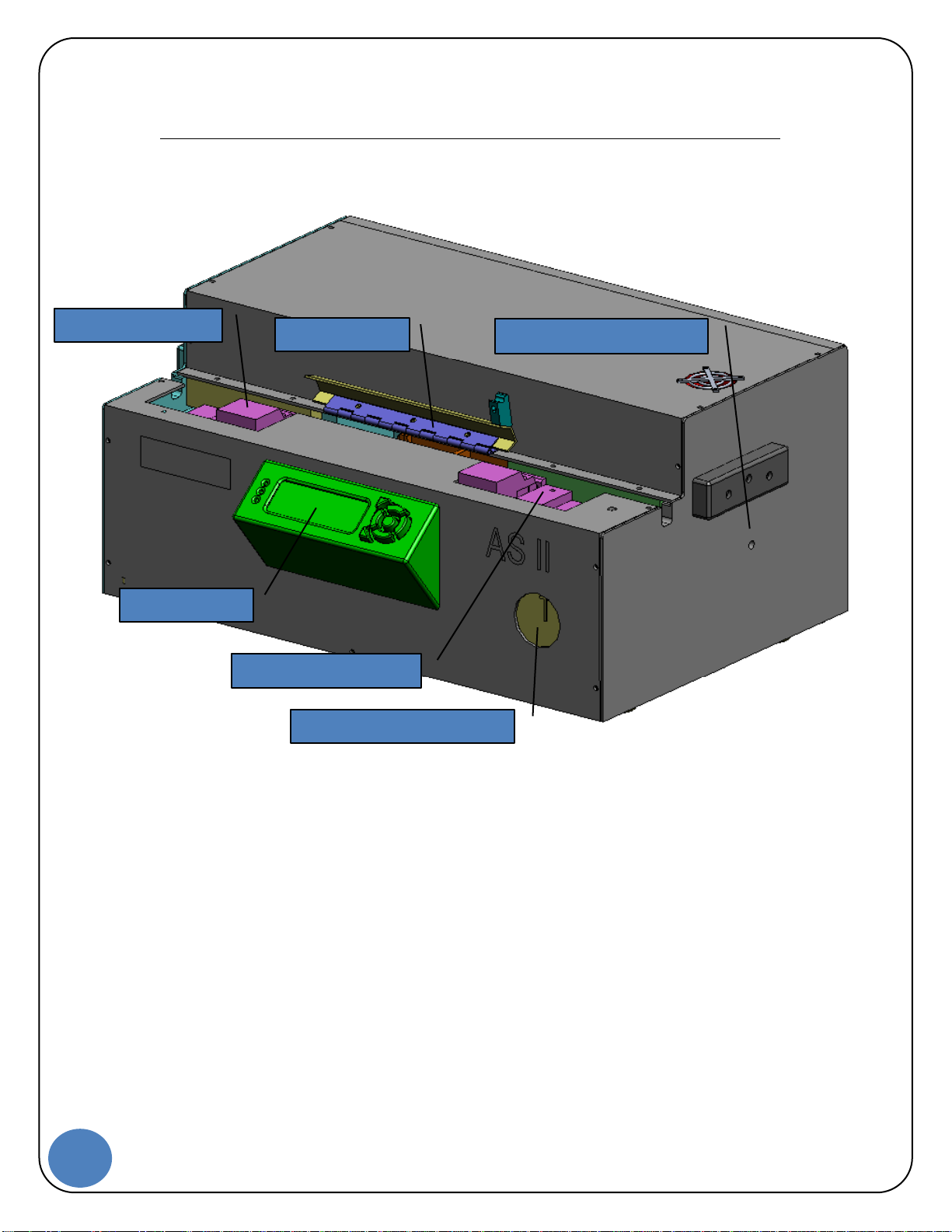
The AS II at a Glance
The AS II comes standard with the following features & add-ons.
Left clamp/button
Safety shield
Heater locking system
LCD display
Right clamp/button
Clamp pressure gauge
12
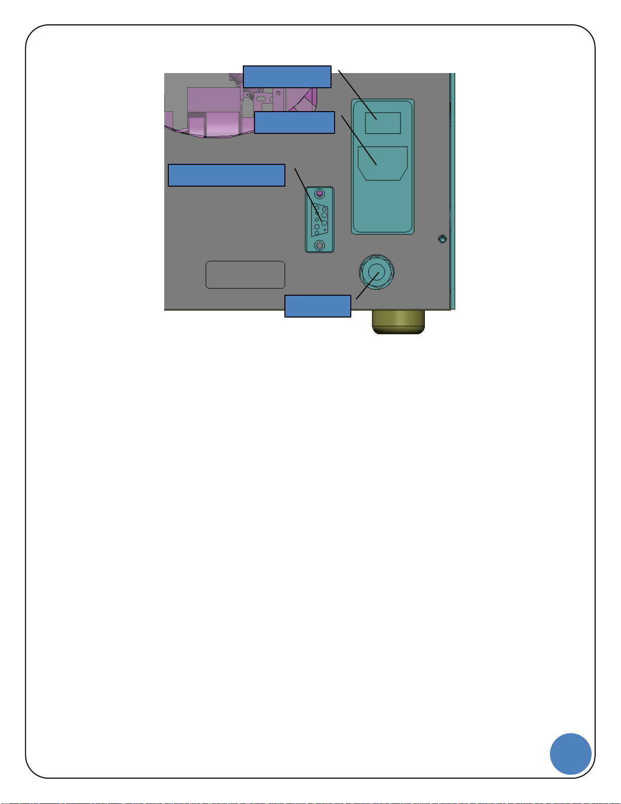
ASII Users Guide | 1/24/2019
Power switch
Power input
Power
RS232 connection
Air input
Power

13
ASII Users Guide | 1/24/2019
Accessories Included
The AS II comes standard with the following accessories.
Item What it’s used for
Power cord Connect the power cord to the AS II, then plug
into a standard power outlet
Air-line (8mm) w/fitting Connect the air-line to the AS II, then plug the fitting
to an air supply
Quick start guide Quick setup guide and operation guide for the ASII
Hex shank bit Used to adjust the clamp pressure
(SPT-10-1326)
Rubber pad (x2) Used to help secure fiber coatings during stripping
(SPT-10-0898)
Optional Accessories
Load cell validation kit Used to verify/adjust the AS II load cell system
(ACC-01-0601)

14
ASII Users Guide | 1/24/2019
Basics
The AS II LCD provides access to all user controls.
AS II Firmware Compatibility
This manual is compatible with the following firmware and above: v1.7
AS II Home Screen
The AS II home screen provides the end user with the following information
•Current program number
•Current status
•Edit option
•Zero option
•Current set temperature
•Real time load cell reading

15
ASII Users Guide | 1/24/2019
AS II Buttons
The AS II buttons allow the end user the ability to
•Access new programs
•Make changes to programs
•Access global parameters
•Zero the load cell
AS II LEDs
The AS II LEDs indicate to the end user the following:
Top LED
•This will be solid green to represent that the unit is on and waiting on the operator. Red
indicates that the unit is in use and the clamps are closed
Middle LED
•Not used
Bottom LED
•Red during heater ramping up and will flash green when the heater is at temperature
Button 2
Power
Button 1
Power
Go button
Power

16
ASII Users Guide | 1/24/2019
Heater Lock
The heater locking system is a new safety feature. The lock secures the heater assembly
during shipping.
Note: Do not power on the unit prior to removing the locking screw, THIS CAN damage the AS
II
1 Spin the locking screw CCW to remove.
2 Insert the protective cap where the locking screw was.
3 Save the locking screw for future shipping.
Safety Shield
The AS II safety shield has a sensor installed for additional security.
•If the safety shield is open, the AS II will not perform an operation
•During a cycle, if the safety shield is opened, the AS II will stop the cycle immediately
Providing Air
Use of an external pressure regulator is required if the line pressure is greater than 95psi. Set
input pressure to 90-95ps before connecting compressed air line to the AS II.
•The AS II is equipped with an 8mm instant push-in fitting
•Push the supply hose into the fitting, making sure that the hose is fully inserted. When the
hose reaches the bottom of the fitting, it will be locked in place
•To remove the hose, push the locking ring in and pull the hose out

17
ASII Users Guide | 1/24/2019
Powering the AS II
1 Connect the power cord to AS II and then plug it into a standard power outlet.
2 Toggle the power switch from off to on.
Upon power-up, the AS II will perform a number of internal tests; if successfully completed, the
top LED on the AS II LCD will become solid green. If unsuccessful, the top LED will become
solid red.
Setting Heater Temperature
The heater temperature is displayed on the front of the unit in real time.
To change the heater temperature:
1 Select the program number that the temperature needs to be changed on.
2 Press Button 2 (labeled Edit).
3 Cycle the Right Arrow Button until ‘Heater temp’ is displayed.
4 Using the Up and Down Arrow Buttons, the temperature can be changed. The Go Button
changes the value from 1 to 100 to accommodate a larger change.
5 Press Button 2 (labeled Save) to keep the current change.
•Allow some time for the heater to adapt for the new temperature setting
Note: If the heater value is set to 0°, then the heater will be turned off
Zero Load Cell Response
•Press Button 2 to zero out the load cell
•If the tension fluctuates 10%, zero out the load cell
Verify the correct voltage is selected, 115V or 230V before powering
on the unit; selecting the incorrect voltage will damage the unit

18
ASII Users Guide | 1/24/2019
Clamp Pressure
The clamp pressure is factory set to 50.
It may be necessary to adjust the clamp pressure for:
•A smaller or larger diameter fiber
•Specialty coated fibers
•When ‘Fiber Slipping’ occurs
•Hex shank bit
1 Adjust the clamp pressure as needed (hex shank bit).
a Turn the dial CW to increase the clamp pressure.
b Turn the dial CCW to decrease the clamp pressure.
c DO NOT over tighten the dial when making adjustments.
Clamp pressure adjustment
Power
19
ASII Users Guide | 1/24/2019
General Use
This section describes the standard operation procedures for using the AS II.
1 Power on the AS II.
2 Choose/verify the program for the fiber diameter/coating.
3 Allow the heater time to reach the operating temperature and stabilize (5 –10 min).
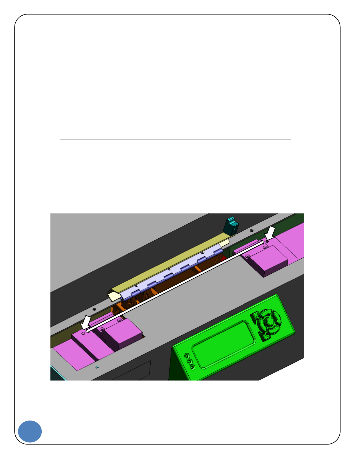
Loading the fiber
4 Open the safety shield to the AS II.
5 Load a fiber across both clamps.
a Make sure that the fiber is flat and taught.
b Make sure that the fiber length passes the buttons.
6 Press both buttons simultaneously.
7 Close the safety shield.
The display will read
Press Start

20
ASII Users Guide | 1/24/2019
8 Press the Go Button.
Note: The proof-test information will only be displayed if that feature is enabled
The display will read
ProofTest Ok (display value here)
The display will read
Done
The display will read
Release Fiber
9 Open the safety shield.
10 Remove the fiber by pressing both buttons simultaneously.
a Make sure to hold the fiber prior to pressing the buttons.
Proof-Test Only
1 Open the safety shield to the AS II.
2 Load a fiber across both clamps.
3 Press both buttons simultaneously.
4 Close the safety shield.
The display will read
Press Start
5 Press the Go Button.
The display will read
ProofTest Ok (display value here)
The display will read
Done
The display will read
Release Fiber
Table of contents


