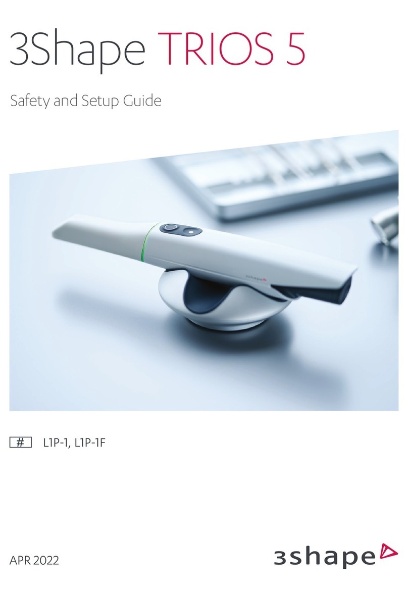
3Shape TRIOS S1P-2 User manual

04-2021
3Shape TRIOS
Safety and Setup Guide
S1P-2, S1P-4, S1A-10, S1A-12, S1A-22

2
ENGLISH
Table of Contents
1. Dear Customer
Thank you forpurchasing your TRIOS®intraoral scanner (IOS)
system from 3Shape TRIOSA/S.
TheTRIOS IOS system enables you toperform anddigitally save oral scans
ofpatient’s teeth foruse indental CAD/CAM systems.
ThisTRIOS safety andsetup guide describes safety precautions, warnings,
andconsiderations related toyour TRIOS IOS system. Forstep-by-step
instructions regarding configurationandoperation ofTRIOS, please refer
totheonline help.
Before assembling orusing TRIOS IOS system, please carefully read andfollow
theinstructions inthissafety andsetup guide andintheonline help system.
Pleasealways keep thissafety andsetup guide near thesystem.
Please observe all safety informationandwarnings toprevent personal injury,
material damage ordamage toyour TRIOS IOS system.
Thank you,
3Shape TRIOSA/S
2. Conformity
Thisguide ispublished by3Shape TRIOSA/S, who reserves
theright toimprove andmodify thecontents without priornotice.
Modifications will, however, be published infuture editions.
All rights reserved.
TRIOS isatrademark of3Shape TRIOSA/S.
Manufacturer Information
3Shape TRIOS A/S, located atHolmens Kanal 7, 1060 Copenhagen, Denmark
is legal manufacturerfor devices listed in this guide.
To learn more about 3Shape, our products and global office locations
please visit our website:www.3shape.com
If you would like to receive a free printed copy please contact 3Shape
DeclarationofConformity (EU):
3Shape TRIOS A/S hereby declares that the TRIOS observes
the provisions of:
• Medical Device Regulation (EU) 2017/745 (MDR),
• Restriction of Hazardous Substances in Electrical
and Electronic Equipment Directive 2011/65/EU (RoHS),
• Waste Electrical and Electronic Equipment Directive
2012/19/EU (WEEE),
• Registration, Evaluation, Authorization and Restriction
of Chemicals Regulation 1907/2006/EC (REACH)
and is in compliance with the following standards: EN (IEC)
60601-1, EN (IEC) 60601-1-2, EN (IEC) 60601-1-6, EN (IEC) 62471.
3. General Information
CAUTION
Be sure to observe all warnings!
Please observe all safety information and warnings
to prevent personal injury, material damage or damage
to your TRIOS IOS system. Safety information and warnings
are highlighted in this guide using the words WARNING,
CAUTION or IMPORTANT NOTICE.
3.1 About this Document – Symbols
The symbols used in this document imply the following:
WARNING
Warnings regarding situations where a medium risk
of injury to persons exists if the information s not observed.
(Black on yellow)
CAUTION
Safety information where hazards such as slight risk
of injury to persons, risk of property damage or damage
to the system exist if the information is not observed.
IMPORTANT NOTICE
Important information that is not a warning/caution
but must be strictly observed.
TIPS
Hints, tips, additional information to support optimal
operation of the system.
3.2 Legend of Labels and symbols
Date of manufacture
Manufacturer
General warning sign– (black on yellow)
1. Dear Customer........................................................................................2
2. Conformity .............................................................................................2
3. General Information................................................................................2
4. Description of TRIOS ..............................................................................3
5. Safety and Warnings................................................................................7
6. Cleaning, Disinfection, and Sterilization................................................ 9
7. Disposal ..................................................................................................11
8. Technical Maintenance......................................................................... 12
9. Consumable Accessories...................................................................... 12
10. Vigilance.............................................................................................. 12

3
ENGLISH
Type BF applied part
WEEE Product disposal symbol
Caution
CE marking
Lot number
Serial Number
Consult instructions for use
Alternating Current
Protective Earth (ground)
Warning – dangerous voltage (black on yellow)
Expiry Date
Standby
LAN Local area network, Ethernet connector (RJ45)
Refer to instruction manual / booklet.
Follow Instruction for Use (white on blue)
Warning (black on yellow): Possibly hazardous optical
radiation emitted from this product. Do not stare
at operating lamp. May be harmful to the eyes. The present
system is in risk group 2.
The calibration patches must not be touched and must not
be exposed to liquids (red on white).
Mass of the TRIOS IOS system,
incl. safe working load (in kilograms)
Identifies the protection tip
Identifies the calibration tip
Medical Device
Global Trade Item Number
Prescription Only (applicable in the United States)
Model Number
4. Description of TRIOS
4.1 Certification and Compliance Notes
CE Marking
This product bears CE marking in accordance with the provisions ofMedical
Device Regulation (EU) 2017/745,Registration, Evaluation, Authorization and
Restriction of Chemicals Regulation 1907/2006/EC, Restriction of Hazardous
Substances in Electrical and Electronic Equipment Directive 2011/65/EU, and
Waste Electrical and Electronic Equipment Directive 2012/19/EU.
CAUTION – EU only
CE marking forconnected products
Further products which are connected tothisunit must
also bear CE marking.
Electrical Safety
This system has been tested to conform with the EN (IEC) 60601-1
Safety Standard for medical electrical devices witha Patient applied
part (the standard title is: Medical electrical equipment – Part 1:
General requirements for basic safety and essential performance),
EN (IEC) 60601-1-2 Medical electrical equipment Part 1-2 General
requirements for basic safety and essential performance - Collateral
Standard: Electromagnetic disturbances - Requirements and tests,
and EN (IEC) 62471 Photobiological safety of lamps.
The system has also been tested to conform with CAN/CSA-C22.2 No.
60601-1:14 and ANSI/AAMI ES60601-1 +C1(2009) + A1 (2012) + A2 (2010).
WARNING
Any person who assembles or modifies a medical electrical
equipment or system complying with the standard EN
(IEC) 60601-1 (safety requirements for medical electrical
equipment) by combining it with other equipment is
responsible for conducting appropriate inspection and
testing to ensure continued safe use of the equipment and
for ensuring that the requirements of this regulation are
met to their full extent for the safety of the patients, the
operators and the environment.
WARNING
Use of the UNIT adjacent to or stacked with other equipment
should be avoided because it could result in improper
operation. If such use is necessary, the UNIT and the other
equipment should be observed to ensure normal operation
in the used configuration.

4
ENGLISH
WARNING
The product needs special precautions regarding
electromagnetic compatibility (EMC) and needs to be
installed and put into service according to the EMC
information provided in the TRIOS Technical Data.
IMPORTANT NOTICE
The system is to be used in a Professional
Healthcare Environment.
4.2 Intended Use
The 3Shape TRIOS 3 IOS system is intended to obtain 3D digital images
of the topographical characteristics of teeth, including bite, gingivae
and palate directly from the patient’s mouth or models of the teeth.
See the online help for a list of supported indications.
CAUTION
Unintended use of the TRIOS IOS system can result in
physical injury to patients, operators and damage the
system.
4.3 Users of TRIOS
The 3Shape TRIOS IOS system is to be operated by legally qualified healthcare
professionals in dental clinics. Using the TRIOS IOS system for any purpose
other than the “intended use” described above may damage the TRIOS IOS
system and harm operators and patients. Proper use of the TRIOS IOS system
includes following the operation and maintenance instructions, and observing
warnings and caution descriptions in this user guide.
WARNING
Carefully follow the instructions in this guide
If the instructions for operating the TRIOS IOS system
as described in this guide are NOT observed, the intended
protection and safety of the user and patient may be impaired.
4.4 Contra-indications
None
4.5 Patient Target Group
No restrictions in patient population
4.6 System Description
The system is available in these variants:
Regional variation can occur regarding the contents of the systems.
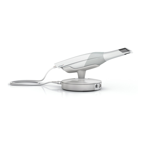
S1P-2 Pen grip scanner, supplied with a pod (holder)
that is connected to an external PC via an Ethernet
cable, and a cord.
S1P-4 Pen grip scanner (monochromatic variant), supplied with
a pod (holder) that is connected to an external PC via an
Ethernet cable, and a cord.
S1A-10 Pen grip scanner, supplied with a MOVE® cart with built-in PC.
S1A-12 Pen grip scanner (monochromatic variant), supplied with
a MOVE cart with built-in PC.
S1A-22 Pen grip scanner, supplied with a MOVE®+ cart with built-in PC.
You can find the figures in the final section of this guide.
All system variants comprise (Figure 1)
• Handheld TRIOS intraoral scanner, S1-2 or S1-4 (S1): Wired handheld
dental intraoral scanner for scanning the surface of the patient’s teeth
either in colour (S1-2) or monochrome (S1-4).
• Scanner Tip (S-Tip) (S2): Re-usable scanner tip attached to the handheld
TRIOS scanner. The tip has a fixed window. When the tip is detached, the
scanner’s optical window (S4) is visible. A set of scanner tips is delivered
with the scanner. The scanner tip must be cleaned and sterilized prior
to first use on a patient and after each use on a patient. The scanner tip
is the only applied part.
• Protection Tip, (S-Ptip) (S3): Protects the optical window of the scanner
from damage and dirt when the scanner is not in use. When the tip
is detached, the scanner’s optical window (S4) is visible.
The scanner tip as well as the protection tip can be attached
by the following procedure:
1. Place the tip over the front tube with the mirror facing upwards or downwards.
2. Mount the tip in a linear direction until a mechanical click is felt.
3. The tip is removed doing the opposite procedure:
4.Pull the tip away from the scanner body (S4).
• Calibration Tip (S-Ctip) (S5): Used for calibrating TRIOS scanners.
• Color Calibration Kit, (S-Ckit) (S6): Used for calibrating TRIOS scanners.
The kit consists of the color calibration target (S7), the sleeve (S8),
and the color calibration adaptor (S9).
• TRIOS software: Scan application/user interface for the scanner.
• Power (mains) cable and plug: The system is delivered with a cable
appropriate for your location. In the USA and Canada, this is a Nema 5-15P
Hospital Grade mains power cord with plug for the MOVE/MOVE+ cart.
System with cart (S1A-10, S1A-12, S1A-22)
furthermore comprises:
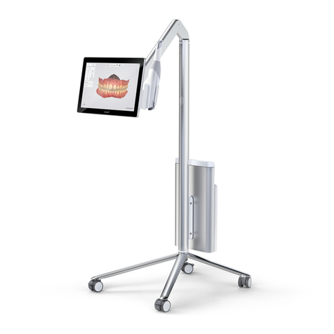
MOVE cart C 4.0 and MOVE+ cart C 4.1 (Figure 2, 3 & 4) for intraoral
digital impression system. Following description applies to both MOVE
and MOVE+ cart:
• Has an adjustable monitor (S10, S11, S12).
• Has a scanner mount (S13) for holding the scanner while not in use.
• Has wheels for mobility (and brakes (S14) if mobility is not desired).
• Computer unit. Attached to the cart for processing, storage and
running the TRIOS software.
• Touch screen: Touch-enabled screen for real-time display of scanning
results generated by the TRIOS software, and for interacting with the
TRIOS software.
• The system standby button (S15) is on the back of the monitor.
• Under the low hinge on the back of the cart a scanner connection
can be found (S16)
• In the bottom (S17), there is a power socket (S18), a network
(LAN) connector (S19), and a fuse drawer (S20). In the top of the
backpack (S21), the dongles are inserted, see description below.
• USB license dongle (access to 3Shape software)
• USB wifi dongle (for connecting cart to wifi network)
• USB port (only MOVE+): The MOVE+ cart has a USB port (Figure 3).
The friction of the arm of the MOVE/MOVE+ cart that holds the scanner
and the display can be adjusted. The corresponding tool is provided with
the system (Figure 4).

5
ENGLISH
Step 1: Move the arm to the top-most position.
Step 2: Insert the tool into the hole on the bottom side of the arm,
located approx. half way along the arm.
Step 3: Turn the tool clockwise to increase friction, anticlockwise
to reduce friction.
Step 4: Adjust friction so that the monitor is steady
(does not sink, does not go up) in the following scenarions:
• Scanner is positioned in scanner holder
• Scanner is not positioned in scanner holder
IMPORTANT NOTICE
Maximum current available for the USB port is 200 mA.
System with pod (S1P-2, S1P-4) furthermore comprises:
Pod with electronics, PS1-2 (Figure 5):
• A mount for the scanner
• Several connection sockets. On one side, there is a single socket
for the scanner. On the other side, there are two connection sockets
for the Ethernet cable to the PC and for the external medical power
supply, respectively.
• A USB license dongle (access to 3Shape software)
4.7 Setting up TRIOS
It is recommended that unpacking, assembly and connection of the TRIOS
IOS system shall be performed by TRIOS authorized technical service
personnel.
CAUTION
If the system has just been delivered from a cold
environment, let it adjust to room temperature to avoid
internal condensation and to allow for proper calibration.
CAUTION
Examine all parts of the system. Look for physical damage,
loose parts or signs of wear that could interfere with proper
use and functionality. Contact your service provider if there
is visible damage or malfunctioning.
System S1A (MOVE/MOVE+ cart) only
Please follow the steps below for assembling TRIOS IOS system (Figure 1&2):
Before you start: Follow the instructions in the packaging to assemble
the foot onto the the MOVE/MOVE+ cart. Tools are provided.
Step 1: Place the MOVE/MOVE+ cart optimally in relation to the patient
chair and your work position.
Step 2: Attach the protection tip to the TRIOS scanner
if not already in place. (S4)
Step 3: Place the scanner on its designated scanner mount
on the MOVE/MOVE+ cart (S13).
Step 4: Connect the scanner cable to the scanner connection socket
on the MOVE/MOVE+ cart behind the screen below the hinge (S16).
• To connect - Push the plug into socket. There is a red orientation
dot on the socket and plug that should match.
• To disconnect - Pull on the outer release sleeve.
Step 5: Connect the MOVE/MOVE+ cart end of the power cable
to the socket at the bottom of the computer unit (S18).
Step 6: Connect the power cable to a grounded power outlet. Ensure
that the MOVE/MOVE+ cart is placed so it does not block the switch on
the mains socket-outlet. To isolate the MOVE/MOVE+ cart and thus the
scanner from supply mains, unplug the flexible power cord from mains.
Step 7: Connect the LAN cable to the MOVE/MOVE+ cart’s LAN
connection at the bottom of the computer unit (S19).
System S1P (pod) only
Please follow the steps below for assembling TRIOS IOS system
(Figure 5 & 6):
Before you start: Place the pod on a flat and horizontal surface optimally
in relation to the patient chair and your work position. Attach the protection
tip to the TRIOS scanner if not already in place. It is easiest not to place
the scanner onto the pod at this time yet, because you may find it easier
to lift the pod while connecting cables in the following.
Step 1: Connect the Ethernet cable to the pod. The cable goes into the
left connection socket on the back side of the pod (the side that has two
connection sockets). If you need to release the Ethernet cable, press on
the small tab on the top of the connector.
Step 2: Connect the power supply to the pod. This cable goes into
the connection socket next to the Ethernet cable described in the
previous step.
• To connect - Push the plug into socket. There is a red orientation
dot on the socket and plug that should match.
• To disconnect - Pull on the outer release sleeve.
The indicator light next to the scanner connection socket will light green.
Step 3: Connect the scanner cable to the scanner connection socket on
the front side of the pod (the side that has only one connection socket).
• To connect - Push the plug into socket. There is a red orientation dot
on the plug that should point upwards.
• To disconnect - Pull on the outer release sleeve.
Now all connections to the pod are established, and you can place
the scanner onto the pod.
Step 4: Connect the other end of the Ethernet cable to the PC (if no
Ethernet ports are available in the PC use an Ethernet to USB adapter)
Step 5: Connect the power (mains) cord to the power supply. The other
end of the power (mains) cable goes into a grounded power outlet
(not shown in the Figure). To isolate the pod and thus the scanner from
supply mains, unplug the power cord from mains.
This manual suits for next models
4
Table of contents
Other 3Shape Dental Equipment manuals
