3Ware 9550SXU User manual

PN: 720-0181-00 www.3ware.com 1
Using the AMCC 3ware®I2C Multiplexer
with a Supermicro®Backplane
The AMCC 3ware I2C Multiplexer (I2C MUX) allows you to connect a
3ware 9650SE or 9550SXU RAID controller to one of 3 Supermicro
backplanes and provide enclosure services for up to 32 drives in a
single enclosure. By using the I2C MUX and the 3ware 9.4.3 software,
you can take advantage of enclosure services such as LED signaling of
drive identification, drive fault indication, and drive rebuild indication.
The I2C MUX supports these 3 Supermicro SAS Backplanes:
•826TQ (12 drive)
•836TQ (16 drive)
•846TQ (24 drive)
This document describes how to connect an I2C MUX to a 3ware
9650SE or 9550SXU RAID controller and to one of the 3 supported
Supermicro backplanes.
What’s included in this package
•AMCC 3ware I2C Multiplexer with full-height bracket attached
•One half-height bracket (for use if needed)
•One I2C-to-controller (upstream) cable, 75 cm, #150-3101-00
•One I2C-to-controller (upstream) cable, 25 cm, #150-3102-00
•Three I2C-to-backplane (downstream) cables, 75cm, #150-3103-00
What you need
•AMCC 3ware I2C Multiplexer and connector cables (this package)
•3ware 9650SE or 9550SXU RAID controller and SATA cables
•Supermicro SAS Backplane 826TQ, 836TQ, or 846TQ
Additional documentation
This document provides information on how to connect the I2C MUX
to your 9650SE or 9550SXU RAID Controller and Supermicro
backplane.
For additional information about 3ware RAID controllers, including
use of the enclosure services, refer to the following documents.
•3ware Serial ATA RAID Controller User Guide, Version 9.4.1
•3ware Serial ATA RAID Controller User Guide, 9.4.3 Addendum
For complete information about the Supermicro backplanes, see the
appropriate documentation at Supermicro’s website.
•http://www.supermicro.com/manuals/other/BPN-SAS-826TQ.pdf
•http://www.supermicro.com/manuals/other/BPN-SAS-836TQ.pdf
•http://www.supermicro.com/manuals/other/BPN-SAS-846TQ.pdf
Using the AMCC 3ware® I2C Multiplexer with a Supermicro® Backplane
2AMCC 3ware I2C MUX Documentation
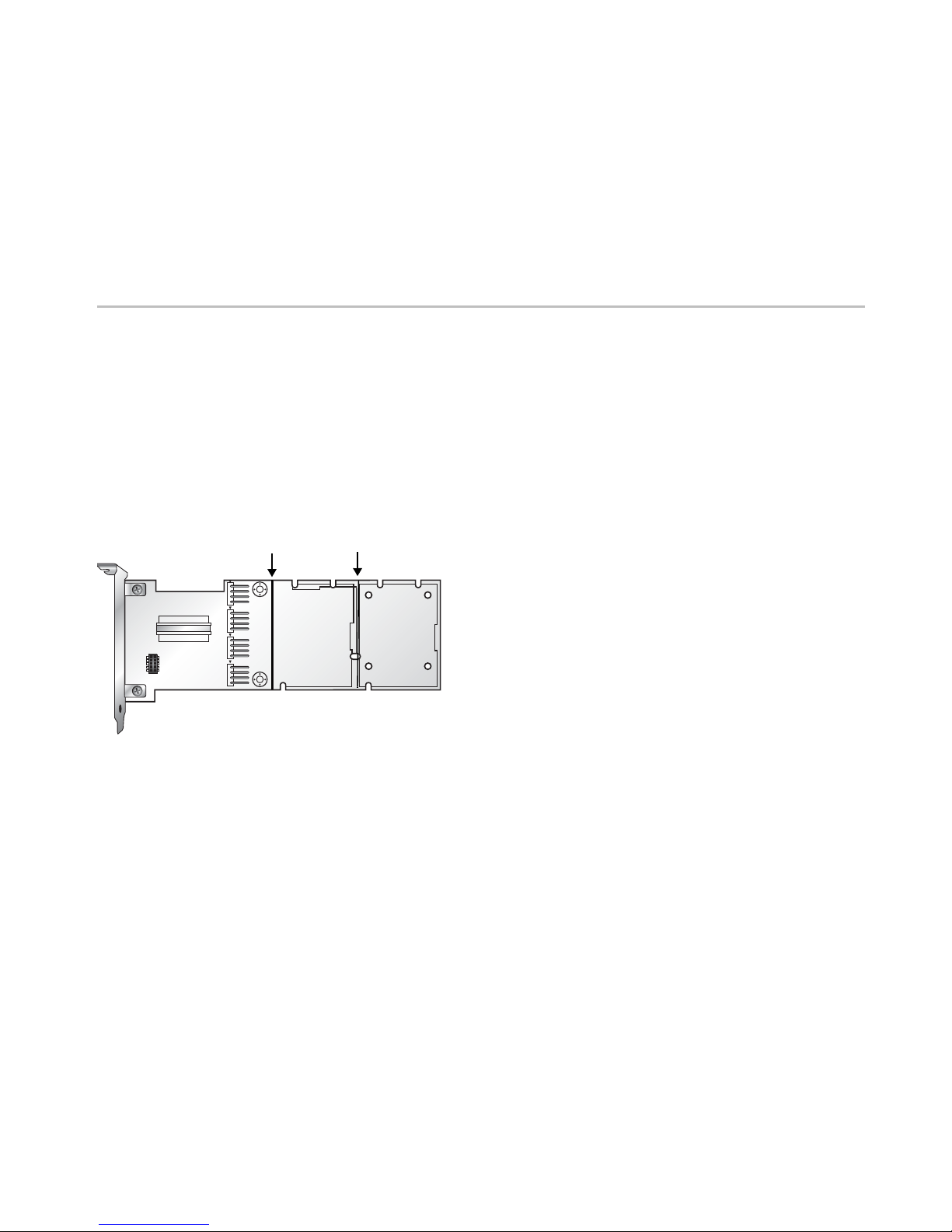
Mounting the I2C MUX
You can mount the I2C MUX in an empty slot or any available space in
the chassis.
The I2C MUX has two break-away sections that can be removed to
make the I2C MUX card smaller. They can also be used as mounting
points for one or two Battery Backup Unit (BBU) batteries, to
maximize space usage inside the enclosure.
You may wish to install the backplane and controller in their respective
enclosures before connecting them via cables.
Connecting to Power
Power is supplied to the I2C MUX via a standard 4-pin Molex power
connector.
Cable Connections
In order for LEDs to be associated with the correct drives, the cable
connections between the I2C MUX, 3ware RAID controller, and
Supermicro backplane need to map to their corresponding port number
or port number groups.
Example: The drive cable that connects to port 1 on the 9650SE RAID
controller must connect to the port 1 SATA connector on the
Supermicro backplane. In addition, the I2C MUX port 0-7 (J4)
connector cable must use one of its two cable ends to connect to
Sideband connector #1 on the backplane, which manages I2C services
for backplane SATA ports 0-3.
The illustrations on pages 3 through 5 show the cable connection
patterns between the I2C MUX and each of the three different
Supermicro backplanes.
The 826TQ and 836TQ backplanes illustrations show a 9650SE-16ML
RAID controller and the 846TQ illustration shows a 9650SE-24M8
RAID controller.
Cable Pin Definitions
Tables showing the proper cable pin definitions are in the Appendix on
page 7.
Jumper Settings
By default, Supermicro SAS Backplanes are set to use I2C to manage
enclosure services. Therefore, the default jumper settings on the
backplanes should not normally need to be adjusted. However, if
the default settings have been changed for any reason, you will
need to change them to the I2C jumper settings.
It is a good idea to review the jumper settings and make sure they are
correct. Tables showing the proper jumper settings for each backplane
are provided in the Appendix on page 6.
Scored line Scored line

Using the AMCC 3ware® I2C Multiplexer with a Supermicro® Backplane
www.3ware.com 3
I2C Multiplexer to Supermicro 826TQ
0
1
2
3
4
5
6
7
8
9
10
11
24
-
31
16
-
23
0
-
7
8
-
15
0
-
3
4
-
7
8
-
11
The black triangle identifying pin 1
on the cable head must be next to
the white triangle identifying pin 1 on
the I2C MUX card.
JP35
Remove jumper cap
if present
JP50
Remove jumper cap
if present
Pin 1 on the cable head is
indicated by the black
triangle. It must connect to
the square pin indicationg
pin 1 on the sideband
connector.
3ware 9650SE-16ML
I2C Multiplexer
4-pin power
connector
I2C MUX to 9650SE cable
Supermicro 826TQ Backplane
Multilane SATA cables
I2C MUX to sideband
connector cables
Sideband connectors

Using the AMCC 3ware® I2C Multiplexer with a Supermicro® Backplane
4AMCC 3ware I2C MUX Documentation
I2C Multiplexer to 836TQ
24
-
31
16
-
23
0
-
7
8
-
15
0
-
3
4
-
7
8
-
11
12
-
16
0
1
2
4
5
6
8
9
10
12
13
14
371115
The black triangle identifying pin 1
on the cable head must be next to
the white triangle identifying pin 1 on
the I2C MUX card.
Pin 1 on the cable
head is indicated by
the black triangle. It
must connect to the
square pin indicating
pin 1 on the sideband
connector.
3ware 9650SE-16ML
I2C Multiplexer
4-pin power
connector
I2C MUX to 9650SE cable
JP35 and JP50
Remove jumper
caps if present
Supermicro 836TQ Backplane
I2C MUX to sideband
connector cables
Multilane SATA cables
Sideband connectors

Using the AMCC 3ware® I2C Multiplexer with a Supermicro® Backplane
www.3ware.com 5
I2C Multiplexer to 846TQ
24
-
31
16
-
23
0
-
7
8
-
15
0
-
7
8
-
15
16
-
23
23 22 21 20
19 18 17 16
15 14 13 12
11 10 9 8
7 6 5 4
3 2 1 0
The black triangle identifying pin 1
on the cable head must be next to
the white triangle identifying pin 1 on
the I2C MUX card.
Pin 1 on the cable
head is indicated by
the black triangle. It
must connect to the
square pin indicating
pin 1 on the sideband
connector.
3ware 9650SE-24M8
4-pin power
connector
I2C MUX to 9650SE cable
I2C Multiplexer
JP35 and JP50
Remove jumper caps if present
JP129
Remove jumper cap if present
Supermicro 846TQ Backplane
I2C MUX to sideband
connector cables
Multilane SATA cables
Sideband connectors

Using the AMCC 3ware® I2C Multiplexer with a Supermicro® Backplane
6AMCC 3ware I2C MUX Documentation
Appendix: Jumper and Cable Pin Settings
Jumper Settings for Supermicro 826TQ
Jumper Settings for Supermicro 836TQ
Note:The following jumper setting information is provided as a reference for your convenience. For complete and current information about the
appropriate I2Csettings for your backplane, be sure to consult the documentation from Supermicro.
Table 1: Reset Chip Settings
These jumpers control the AMI 9072 and AMI 9071 chips
Jumper Jumper Settings Note
JP35 Open: No Reset (Default)
Closed: Reset This is a 2-pin jumper block.
Jumper should be removed.
JP50 Open: No Reset (Default)
Closed: Reset This is a 2-pin jumper block.
Jumper should be removed.
Table 2: I2C Setting (Default)
These jumpers control the I2C and SGPIO settings for the 826TQ
Jumper JumperSetting Note
JP65 2-3 Backplane ID SDIN #1
JP67 2-3 Backplane ID SDIN #2
JP 74 2-3 Backplane ID SDIN #3
JP83 Closed I2C Reset #1
JP84 2-3 Controller ID #1
JP85 1-2:ID#0 Backplane ID #1
JP86 Closed I2C Reset #2
JP87 Open Reset SDOUT #1
JP88 Open Reset SDOUT #2
JP89 Closed Reset #3
JP90 2-3 Controller ID #3
JP91 1-2:ID#0 Backplane ID #3
JP93 Open Reset SDOUT #3
JP101 2-3 Controller ID #2
JP102 2-3:ID#1 Backplane ID #2
Table 3: Reset Chip Settings
These jumpers control the AMI 9072 chip
Jumper Jumper Settings Note
JP35 Open: No Reset (Default)
Closed: Reset This is a 2-pin jumper block.
Jumper should be removed.
JP50 Open: No Reset (Default)
Closed: Reset This is a 2-pin jumper block.
Jumper should be removed.
Table 4: I2C Setting (Default)
These jumpers control the I2C and SGPIO settings for the 836TQ
Jumper Jumper Settings Note
JP65 2-3 Backplane ID SDIN #1
JP67 2-3 Backplane ID SDIN #2
JP 74 2-3 Backplane ID SDIN #3
JP83 Closed I2C Reset #1
JP84 2-3 Controller ID #1
JP85 1-2:ID#0 Backplane ID #1
JP86 Closed I2C Reset #2
JP87 Open Reset SDOUT #1
JP88 Open Reset SDOUT #2
JP89 Closed Reset #3
JP90 2-3 Controller ID #3
JP91 1-2:ID#0 Backplane ID #3
JP93 Open Reset SDOUT #3
JP101 2-3 Controller ID #2
JP102 2-3:ID#1 Backplane ID #2
JP103 2-3 Controller ID #4
JP104 2-3:ID #1 Backplane ID #4
Using the AMCC 3ware® I2C Multiplexer with a Supermicro® Backplane
www.3ware.com 7
Jumper Settings for Supermicro 846TQ
Cable Pin Definitions
For additional information about using the enclosure services of your
Supermicro Backplane, please consult the documentation that came
with your chassis or backplane.
Copyright ©2008 Applied Micro Circuits Corporation (AMCC). All rights reserved. 3ware® and 3DM® are registered trademarks of AMCC. The 3ware logo, 3BM, StorSave are
all trademarks of AMCC. Supermicro® is a registered trademark of Supermicro Computer, Inc. All other trademarks herein are property of their respective owners.
While every attempt is made to make this document as accurate as possible, AMCC assumes no responsibility for errors or omissions in the document and shall not be responsible
or liable for any and all damages, claims and/or disputes that arise from dependence on this publication.
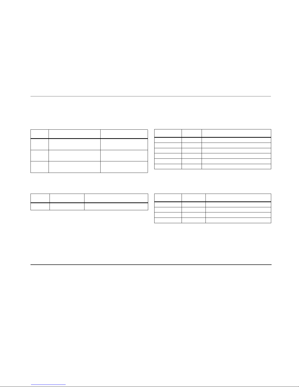
Table 5: Reset Chip Settings
These jumpers control the AMI 9072 chips
Jumper Jumper Settings Note
JP35 Open: No Reset (Default)
Closed: Reset This is a 2-pin jumper block.
Jumper should be removed.
JP50 Open: No Reset (Default)
Closed: Reset This is a 2-pin jumper block.
Jumper should be removed.
JP129 Open: No Reset (Default)
Closed: Reset This is a 2-pin jumper block.
Jumper should be removed.
Table 6: I2C Setting (Default)
This jumper controls the I2C and SGPIO settings for the 846TQ
Jumper Jumper Settings Note
JP84 2-3 Jumper should connect pins 2 and 3.
Table 7: Cable pins - I2C MUX to 9650SE or 9550SXU
Signal I2C MUX 3ware 9650SE or 9550SXU
Reset (SB4) Pin 3 Pin 3
Ground (SB2) Pin 4 Pin 4
SDA (SB1) Pin 5 Pin 5
Ground (SB3) Pin 6 Pin 6
SCL (SB0) Pin 7 Pin 7
IRQ Pin 9 Pin 9
Table 8: Cable pins - I2C MUX to Supermicro backplane
Signal I2C MUX Supermicro 836TQ
SDA Pin 1 Pin 1
Ground Pin 2 Pin 2
SCL Pin 3 Pin 3
Not Connected Pin 4 Pin 4
This manual suits for next models
2
Popular Multiplexer manuals by other brands


Elcon
Elcon MUX 2700 instruction manual

Agilent Technologies
Agilent Technologies E1343A User's manual and programming guide

Analogic
Analogic bk ultrasound bkSpecto INSTALLATION PROCEDURE

Racal Instruments
Racal Instruments 1260-100X X Series user manual

Harris
Harris Intraplex STL-160 Series Installation & operation manual

ADTRAN
ADTRAN Total Access 3000 Installation and Maintenance


