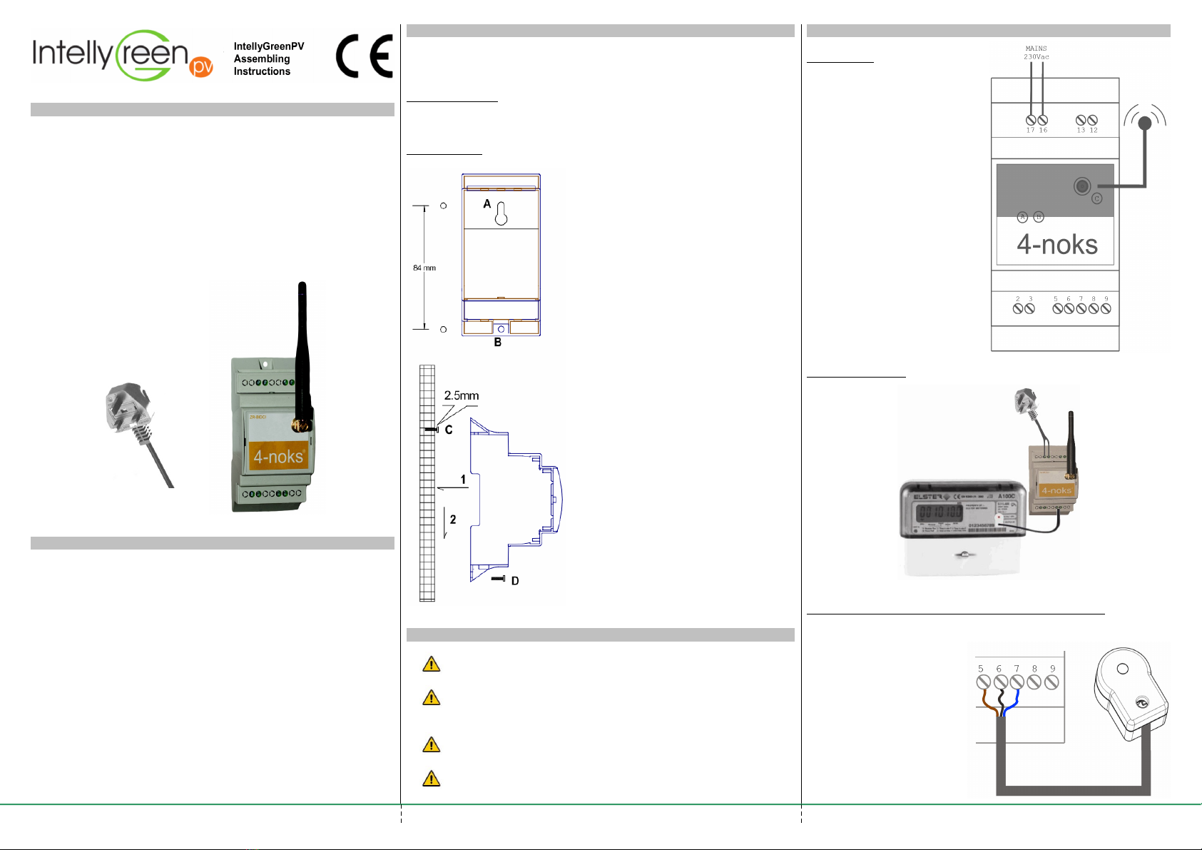
manuals.online logo
Brands
  1. Home
  2. •
  3. Brands
  4. •
  5. 4-noks
  6. •
  7. Transmitter
  8. •
  9. 4-noks IntellyGreenPV ZR-TIDCI.D-PV-EM Installation guide

4-noks IntellyGreenPV ZR-TIDCI.D-PV-EM Installation guide

OVERVIEW OF ZR-TIDCI.D-PV-EM
The device ZR-TIDCI.D-PV-EM, also known as "Radio Transmitter", is
meant to connect wirelessl a Generation Meter to the Intell GreenPV
In-house Displa . Its task is to count the pulses generated b the
Generation Meter (watt-hour measurement) and to transmit that value
c clicall .
The ZR-TIDCI.D-PV-EM device replaces the device normall present in
the standard Intell GreenPV Basic kit (coded as device ZR-TIDCI-
OPT1EM).
The information in this document, especiall if related to electrical
wiring, is intended to replace what is stated elsewhere in the
Intell GreenPV standard documentation.
The device is supplied with antenna and a power suppl cord.
The kit includes:
(1) n.1 ZR-TIDCI.D-PV-EM
(2) n.1 Antenna
(3) n.1 Power suppl cord
CHARACTERISTICS OF ZR-TIDCI.D-PV-EM
Size: 53 x 110 mm x 65 mm
Weight: 100 g
Power suppl : 85-250 Vac; 50/60Hz;
Connections: Screw Terminal
Operating Range: -10°C ÷ +55°C; <80%
Degree of protection: IP 30
Radio Features:
Range Indoor/Outdoor: 25m / 100m
Trasmission Power: 10 mW (10 dBm)
Frequenc : 2405 -2480 MHz
Sensitivit : -97dBm
External antenna gain: 5.5 dBmi
DSSS Modulation
IEEE 802.15.4 compliant
Ember Chip EM250
Stack Zigbee PRO Ember
ASSEMBLING THE ZR-TIDCI.D-PV-EM
The device is designed to be installed on DIN rail inside Cabinets.
Alternativel , the device can be attached directl to the wall with 2 anchors,
hole diameter 5mm.
DIN rail mounting:
The DIN rail mounting is standard.
The device is compatible with DIN EN 60715.
Wall mounting:
To mount the device to the wall, follow these instructions:
WIRING THE DEVICE
Caution: The wiring must be performed b trained personnel.
Caution: Connect the device to a power line adequatel
protected against short circuits and overloads exceeding the
Maximum power handling.
Caution: Connect the device in accordance with what established
under national law.
Caution: Do not execute wiring if the device is powered.
WIRING THE DEVICE
Connections:
(A) – Bicolor Led
(B) – Disassociation Button
(C) – Antenna Connector
(5) – Counting Input
(6) – Gnd
(7) – Vcc
(8) – Alarm Input
(9) – Gnd
(17) – Power Suppl 230V
(16) – Power Suppl 230V
Functional Diagram
Connecting counting input to the optical interface (optional)
(5) – Counting Input – Brown Wire
(6) – Gnd – Black Wire
(7) – Vcc – Blue Wire
4-noks s.r.l. - Francenigo di Gaiarine (TV) Ital
(2)
(1)
Drill two 5mm holes on the wall at 84mm
distance, correspondent to the notch A and
to the hole B present on the bottom of the
case.
Screw a screw to wall plug C, without
tighten, leaving about 2.5 mm of space
between the head of screw and the wall
surface.
Place the module to the wall so that the
screw C fits into the device's notch A.
Slide the module down until ou see
through hole B the relative wall plug.
Screw the screw D tightening to ensure the
mechanical fixing of device
(3)
WIRING THE DEVICE
Connecting counting input to a clean contact output (S0 output)
Connect S0 output to
terminal (5) and (6)
Connecting alarm input to a clean contact output (S0 output)
Connect S0 output to
terminal (8) and (9)
Warin :
If an optical interface is not used, make sure the counting
input (and alarm input) is connected to outputs with voltage
free contact.
Do not appl differences of potential to these terminals
contacts.
Otherwise, the device ma be damaged be ond repair.
OPERATING CONTROLS
Button
If pressed for longer than 10 seconds the device is reset to its original
state (disconnected device).
This action causes the loss of data relating to the radio communication
and the loss of connection with the In-house Displa and all devices
connected to it.
LIGHT SIGNALS
Led State Description
Continuous light orange.
Short flash ever 20
seconds.
Indicates that the device is not
connected to an radio network.
Flashing Green Flashing indicates that the
device is operating normall .
ASSOCIATION TO THE IN-HOUSE DISPLAY
Normall the device is supplied in the kit along with the In-house Displa and
normall the two objects are alread connected and therefore able to work
immediatel after their powering, without additional configuration.
If for some reason there's no association between the two devices (because
of the disconnection of the In-house Displa or Radio Transmitter) ou can
connect them again.
Association of the device:
1) Turn on In-house Displa and Radio Transmitter
2) Verif that the Radio Transmitter is not connected to an radio
network (the LEDs are all switched on and perform a quick flash
for two seconds ever 20 seconds), otherwise disassociate the
device b pressing the button for more than 10 seconds.
3) Acting on the In-house Displa , open the radio network
(Menu/Radio Management/ Open Radio Network) following the
steps:
A few seconds after opening the network, the device should connect to the
radio network of the remote displa . The operation's success is highlighted
b the flashing of led LD1 of the device.
If after 30 seconds from the opening of the network the device is still not
connected, ma be the chosen location is not suitable; in this case place the
device closer to the In-house Displa or install another Repeater (ZR-
REPE230M).
When finished, close the radio network via In-house Displa .
STANDARDS
Regulations: 2006/95/CE, 89/336/CE, 99/5/CE
Standards: EN 300 328, EN 301 489, EN 61000-6-2, EN 6100-6-3,
EN 60950-1
Disposal
In case of disposal, the products must be disposed of separatel in
accordance with applicable local laws.
Warranty Conditions
The warrant period is 2 ears from the date of installation or 30 months
from the date of manufacture.
The warrant applies onl in UK.
The manufacturer agrees to replace or repair the components that are
found defective.
Damage caused b improper installation, b a power suppl not
compliant with the CEI EN 50160 standard, b the incorrect use or
failure to compl with the instructions contained in the Assembling
Installation is not covered b the warrant .
NOTES:
4-noks s.r.l. - Francenigo di Gaiarine (TV) Ital
Confirm this request to open
the In-house Displa radio
network
At the end of the association
process, confirm this request to
close the In-House Displa
Radio Network
Press the button under "Menu"
Select "Open Radio Network"
INSTRUCTIONS INPV
SERIES
VERSION
DATE
001
1.4
06 / 2011

Popular Transmitter manuals by other brands

Sennheiser SR 2050 IEM Specifications

Sennheiser

Sennheiser SR 2050 IEM Specifications

Kramer 610T user manual

Kramer

Kramer 610T user manual

Moore Industries TDY user manual

Moore Industries

Moore Industries TDY user manual

Hycontrol VF04 User and programming manual

Hycontrol

Hycontrol VF04 User and programming manual

MSA SMC 5100-99-IT operating manual

MSA

MSA SMC 5100-99-IT operating manual

Vaisala CARBOCAP GMM112 Quick reference guide

Vaisala

Vaisala CARBOCAP GMM112 Quick reference guide

S.t. Innovators TEX – U1 user manual

S.t. Innovators

S.t. Innovators TEX – U1 user manual

Greystone Energy Systems PMRMC Series installation instructions

Greystone Energy Systems

Greystone Energy Systems PMRMC Series installation instructions

Rice Lake SCT-1000ETHERNET Operation manual

Rice Lake

Rice Lake SCT-1000ETHERNET Operation manual

Amco AquaMaster Series installation manual

Amco

Amco AquaMaster Series installation manual

Lectrosonics UM200 operating instructions

Lectrosonics

Lectrosonics UM200 operating instructions

M-system CTS2 instruction manual

M-system

M-system CTS2 instruction manual

Audio Limited 2040 user guide

Audio Limited

Audio Limited 2040 user guide

Magellan MG-DCTXP installation manual

Magellan

Magellan MG-DCTXP installation manual

Vega VEGABAR 86 Quick setup guide

Vega

Vega VEGABAR 86 Quick setup guide

Canon Wireless Transmitter WFT-E5A instruction manual

Canon

Canon Wireless Transmitter WFT-E5A instruction manual

Heathkit DX-20 Assembly and operation

Heathkit

Heathkit DX-20 Assembly and operation

NIVELCO THERMOCONT TT Series Installation and programming manual

NIVELCO

NIVELCO THERMOCONT TT Series Installation and programming manual

manuals.online logo
manuals.online logoBrands
  • About & Mission
  • Contact us
  • Privacy Policy
  • Terms and Conditions

Copyright 2025 Manuals.Online. All Rights Reserved.