Seneca K120RTD User manual

K120RTD
2 WIRE - LOOP POWERED TRANSMITTER FOR PT100 AND NI100 PROBES
General Description
The K120RTD instrument converts a temperature signal read by a PT100 (EN 60 751) or
NI100 probe with connection by 2, 3 or 4 wires into a signal normalised in current for 4 20-
mAloop (2 wires technology).
The module's main features are:
ENGLISH - 1/8
EN
Technical Features
Measurement Range :
Resistance Range :
Minimum span :
Current on sensor :
Cable resistance :
Connection :
Resolution :
-200 - +650 °C
18,5 - 330Ω Ω
20 °C
750 A ratedm
Max 25 per wireΩ
2, 3 or 4 wires
~ 6 mW
PT100 Input- EN 60751/A2 (ITS-90)
Measurement Range :
Resistance Range :
Minimum span :
Current on sensor :
Cable resistance :
Connection :
Resolution :
-60 - +250 °C
69 - 290Ω Ω
20 °C
750 A ratedm
Max 25 per wireΩ
2, 3 or 4 wires
~ 6 mW
NI100 Input
5 30 V- DC
4 - 20 mA, 20 - 4 mA(2 wires technology)
1 k @ 26 V , 21 mA (see on page 2,ΩDC Load Resistance
vs Minimum Functioning Voltage diagram)
1 A(>14 bits)m
102,5% of full scale value (see Table on Page 5)
105% of full scale value (see Table on Page 5)
approximately 30 mA
Functioning Voltage :
Current output :
Load resistance :
Resolution :
Output in case of over-range :
Output in case of fault :
Current output protection :
Output/Power Supply
MI00124 -E2
%High precision.
%16 bit resolution.
%Extremely compact size (6.2 mm).
%Attachment to a 35 mm DIN rail.
%Configurabilty by PC with xxxxx dedicated software.
%Configurability by DIP-switch.

ENGLISH - 2/8
1200
800
400
0
R =((U-5)/0.021)
Load
5 10 15 20 25 30
Minimum Functioning Voltage U (V )
DC
Standards : EN61000-6-4/2002-10 (electromagnetic emission,
industrial surroundings)
EN61000-6-2/2006-10 (electromagnetic immunity,
industrial surroundings)
Operating Conditions :
Storage Temperature:
LED Signalling :
Connections :
Conductor Section :
Wire stripping :
Box:
Dimensions, Weight :
Temperature -20 +65 °C-
Humidity 30 90 % at 40°C (non-condensing)-
Altitude: up to 2000 m.a.s.l
-40 +85 °C-
Setting error, connection , internalfault fault
Spring terminals
0,2 - 2,5 mm2
8 mm
PBT (black colour)
6,2 x 93,1 x 102,5 mm, 45 g
Diagram: Load Resistance vs Minimum Functioning Voltage
RLoad ( )W
MI00124 -E2
Other Features
50 Hz and 60 Hz (settable)
Max of 0,1% (of measurement range) or 0,1 °C
< 0,5 %
0,005 /W W
< 100 ppm, Typical : 30 ppm
100 ms (without 50/60 Hz rejection)
300 ms (with 50/60 Hz rejection enabled)
< 220 ms (without 50/60 Hz rejection)
< 620 ms )(with 50/60 Hz rejection enabled
IP20
Protection Index :
(*) EMI: electromagnetic interferences.
Network Freq. Rejection :
Transmission error :
Error caused by EMI (*)
Influence of cable resistance :
Temperature Coefficient :
Sampling Time:
Response time (10 - 90 %) :

ENGLISH - 3/8
1 -Attach the module in the upper part of
the rail.
2 - Press the module downwards.
1 -Apply leverage using a screwdriver (as
shown in the figure).
2 - Rotate the module upwards.
Assembly in vertical position is recommended in order to increase the module's
ventilation, and no raceways or other objects that compromise aeration must be positioned
in the vicinity.
Do not position the module above equipment that generates heat; we recommend
positioning the module in the lower part of the control panel or container compartment.
RTD wiring
50 / 60 Hz Rejection filter
Reversed Output
RTD Type
Measurement Range Start
Measurement Full- Scale
Output signal in case of
Fault
Over-Range
3 wires
present
NO
PT100
0 °C
100 °C
Towards the top of the output range
YES: a 2.5% over-range value is acceptable;
a 5% over-range value is considered a fault.
MI00124 -E2
SETTING BY DIP-SWITCHES
Configuration from memory
The module leaves the factory with all the DIP-switches in OFF position.
In this position the module uses the configuration saved in memory. This configuration may
be modified by PC (see section).Setting by PC
The default configuration is the following (if no other indications are present on the
instrument):
MODULE CONFIGURATION
The module may be configured both by DIP-switches and by PC.
If only a DIP-switch is not in OFF position, the configuration saved in memory is not used (it
K120RTD
K120RTD
Inserting the module in the rail Removing the module from the rail
Installation rules
This module has been designed for assembly on a DIN 46277 rail.

ENGLISH - 4/8
For a customized setting of the module, the positions of the DIP-switch are illustrated on
the following tables.
Note: for all following tables:
The indication indicates that the DIP-switch is set in ON Position.
No indication is provided when the DIP-switch is set in OFF Position.
RTD WIRING
1
SW1
3 wires connections
2 / 4 wires connection
50 / 60 Hz REJECTION FILTER (*)
2
SW1
Present
Absent
(*) The filter slows down the response time to around 620 ms and guarantees the
repeating of the disturbance signal at 50 / 60 Hz overlapping the measurement signal.
REVERSED OUTPUT
3
SW1
Reversed: 20 - 4 mA
Normal: 4 - 20 mA
MEASUREMENT RANGE START
6SW1 7 8 °C
0
-10
-20
-40
-50
-100
-150
-200
RTD TYPE
4
SW1
PT100
NI100
NOT USED
5SW1 Not used
MI00124 -E2
Custumized Setting
is not modified and will be used again with all the DIP-switches in OFF position) and so it is
necessary to program all the parameters as it is indicated on the tables of the following
section.

ENGLISH - 5/8
OVER-RANGE (*)
8SW2
YES: a 2.5% over-range value is acceptable;
a 5% over-range value is considered a fault.
NO: the fault alone causes a 2.5% over-range value.
MEASUREMENT FULL SCALE
1 1SW2SW2 1SW22 2 23 3 34 4 45 5 56 6 6°C °C °C
0 120 340
5 130 350
10 140 360
15 150 370
20 160 380
25 170 390
30 180 400
35 190 410
40 200 420
45 210 430
50 220 440
55 230 450
60 240 480
65 250 500
70 260 520
75 270 550
80 280 580
85 290 600
90 300 620
95 310 650
100 320
110 330
(*) See the table below for the corresponding values.
Output signal limit Over-range / Fault ±2,5 % Fault ±5 %
20 mA 20,4 mA 21 mA
4 mA 3,6 mA < 3,4 mA
OUTPUT SIGNAL IN CASE OF FAULT
7SW2
Towards the top of the output range
Towards the bottom of the output range
MI00124 -E2
Configuration by PC
The configuration by PC use is possible with the following accessories:
S117P: USB to RS232 / TTL
PM002411: connection cable between S117 and K120RTD
Z120: Dedicated programming software.

ENGLISH - 6/8
Electrical Connections
8 mm
0,2..2,5 mm2
The module has been designed for spring-type terminal
electrical connections.
Proceed as follows to make the connections:
1 - Strip the cables by 0.8 mm
2 - Insert a screwdriver in the square hole and press it
until the cable lock spring opens.
3 - Insert the cable in the round hole.
4 - Remove the screwdriver and make sure that the cable
is tightly fastened in the terminal.
MI00124 -E2
The configuration may be written to memory with the DIP-switches in any position, but the
saved parameters are used only with all the DIP-switches in OFF position.
%Start and Full scale values.
%RTD Connection: 2 wires, 3 wires or 4 wires.
%50 / 60 Hz Rejection:Absent or Present.
%Measurement filter:Absent or Present (1, 2 , 5 , 10, 30, 60 seconds).
%Output: Normal (4 - 20 mA) o Reversed (20 - 4 mA).
%RTD Type: PT100 or NI100.
%Cable Resistance Compensation for 2 wires measurement.
%Output signal in case of fault: t or t
owards the bottom of the output range owards the top
of the output range.
It is besides possible the calibration of the output scale.
The module may be programmed even if it is not supplied by the 4 20 mA loop, since the-
power supply is provided through the programming connector.
The interface to program the module is available under the the frontal cover:
Once the user has at his disposal the above listed accessories, the following parameters
may be set:
15
6 2
Programming
K120RTD

ENGLISH - 7/8
Input
The module accepts input from a PT100 (EN 60 751) or NI100 temperature probe with
connection by 2, 3 or 4 wires.
The use of shield cables is recommended for the electronic connections.
2-wire connection
This is the connection to be used for short distances ( < 10 m) between module and probe,
bearing in mind that it adds an error (which may be removed by sofware programming)
equivalent to the resistance contributed by the connection cables to the measurement.
DIP-switch SW1-1 set in ON Position (2 / 4 wires) or all DIP-switches in OFF position
(configuration from memory: module programmed by PC for 2 wires connection).
With bridges between Terminals 1 and 2 and Terminals 3 and 4.
3-wire connection
This is the connection to be used for media-long distances ( > 10 m ) between module and
probe. The instrument performs compensation for the resistance of the connection cables.
In order for compensation to be correct, it is necessary that the resistance values of each
conductors be the same because in order to perform compensation the instrument
measures the resistance of only one conductor and assumes the resistance of the others
conductors to be exactly the same.
DIP-switch SW1-1 set in OFF Position (3 wires) or all DIP-switches in OFF position
(configuration from memory: module programmed by PC for 3 wires connection).
With bridge between Terminals 3 and 4.
4-wire connection
This connection to be used for media-long distances ( > 10 m ) between module and probe.
Provides the maximum precision because the instrument measure the resistance of the
sensor independently of the resistance of the connection cables.
DIP-switch SW1-1 set in ON Position (2 / 4 wires) or all DIP-switches in OFF position
(configuration from memory: module programmed by PC for 2 wires connection).
15
6
7
8
2
3
4
OUTPUT
INPUT
RTD 4 wires RTD 3 wires RTD 2 wires
MI00124 -E2
1
2
3
4
1
2
3
4
1
2
3
4
JJJ

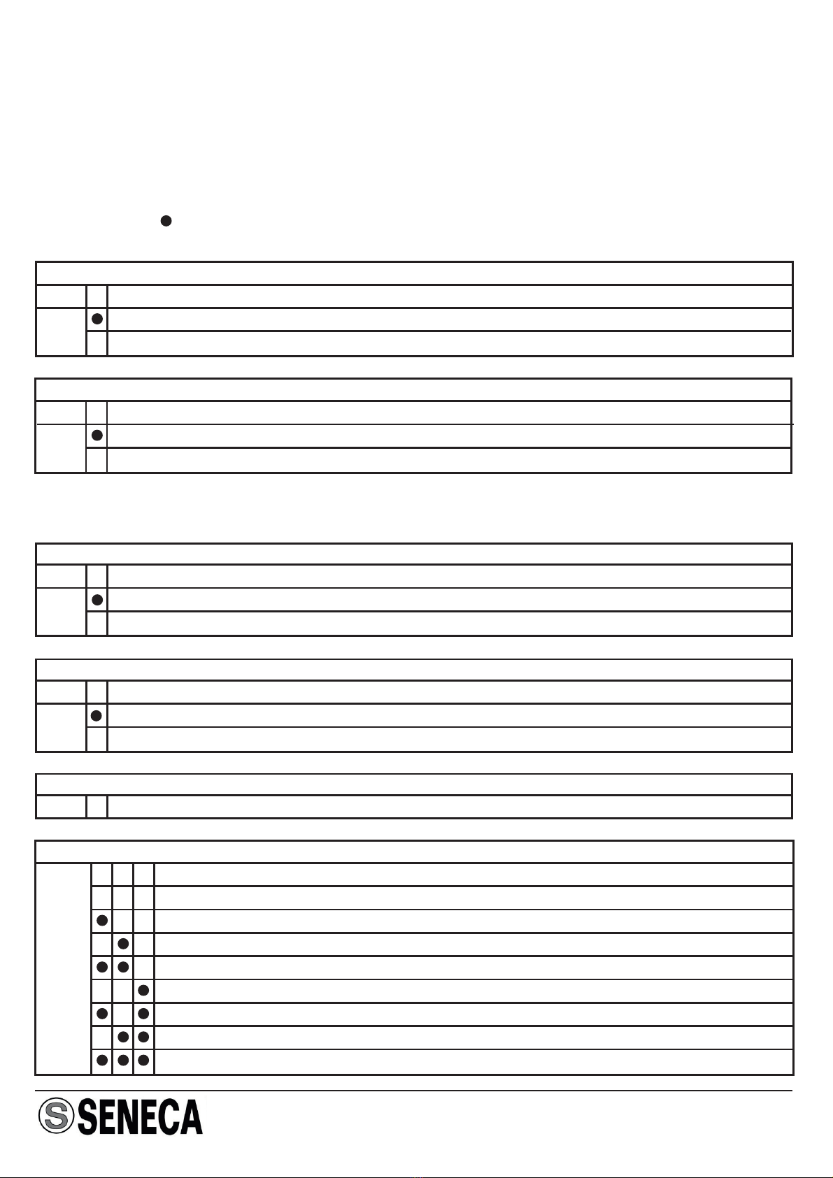
LED indications on the frontal panel
LED Meaning
Rapid flashing
3 pulses/sec.
Internal fault
Slow flashing
1 pulse/sec.
DIP-switch setting error (full scale and start range limits)
Steady light RTD connection wire fault.
Measurement out of range, 3 wire resistance out of range.
rd
Output
Current loop connection (regolated current).
The use of shield cables is recommended for the electronic connections.
Note: in order to reduce the instrument's dissipation, we recommend guaranteeing a load
of > 250 n
Ωto the curre t output.
15
6 2
3
4
OUTPUT
INPUT
+
-
U
Iout
RLoad
MI00124 -E2 ENGLISH - 8/8
Disposal of Electrical & Electronic Equipment (Applicable throughout the European Union and other
European countries with separate collection programs)
This symbol, found on your product or on its packaging, indicates that this product should not be treated as
household waste when you wish to dispose of it. Instead, it should be handed over to an applicable
collection point for the recycling of electrical and electronic equipment. By ensuring this product is
disposed of correctly, you will help prevent potential negative consequences to the environment and
human health, which could otherwise be caused by inappropriate disposal of this product. The recycling of
materials will help to conserve natural resources. For more detailed information about the recycling of this
product, please contact your local city office, waste disposal service or thè retail store where you
purchased this product.
SENECA s.r.l.
Via Austria, 26 - 35127 - PADOVA - ITALY
Tel. +39.049.8705355 - 8705359 - Fax +39.049.8706287
This document is property of SENECA srl. Duplication and reprodution are forbidden, if not authorized. Contents of the
present documentation refers to products and technologies described in it. All technical data contained in the document
may be modified without prior notice Content of this documentation is subject to periodical revision.
Table of contents
Other Seneca Transmitter manuals