DRILL AREA PREPARATION
The beadlock inner tube valve stem hole should be located about
20cm circumferentially from the standard valve stem hole in
either direction.
Although directly across from the standard valve stem hole seems
proper, with this, it is more difficult to mount the final outside
tire bead.
* Double check your measurements and positioning, before drilling the hole! *
Check exactly where you plan to drill the beadlock valve stem hole while checking for:
1) A flat spot to receive the O-ring, and
2) For rim thickness. The 8mm valve stem will accommodate any thickness of rim up
to 13mm and requires a 16mm diameter flat surface to receive the O-ring, washer
and nut.
We recommend 6mm or more of valve stem-to-inside- rim clearance and more may be
required to use your style air pressure gauge. With most rims, this is easily determined by
looking at the rim as normally mounted on the lugs. Again, check twice and drill once!
DRILLING PROCEDURE
1) Use a center punch mark the hole.
2) Drill at a right angle to the center-punched surface.
3) Drill in stages, first 4mm, then 8mm.
4) Deburr both the outside and inside of the hole.
5) Remove all chips from within the tire with a cloth, if you drill
with the tire half on the rim.
6) Do not use compressed air to blow the chips out, but rather
vacuum or wipe them out. Left inside the tire, these chips
can eventually chafe and wear through the beadlock casing,
inner tube or both. 4x4 Traction is not responsible for this
type of failure or product replacement. Keep everything
very clean and smooth.
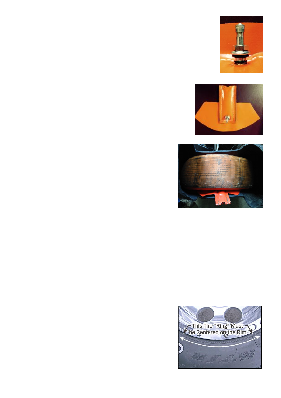
RIM PREPARATION
1) Remove all dirt, flaking paint, rust, burrs and corrosion from the entire inside
surface and edge of the rim. Pay particular attention to the tire-bead-seating
surface. The condition of this surface sets the air seal integrity and rim-to-tire
anti-spin adhesion. We recommend wire brushing this entire surface along with the
rim’s bead bumps.
2) Next, remove the standard valve stem. Mark or remember this hole is for the
special air channel, which feeds the main tire.
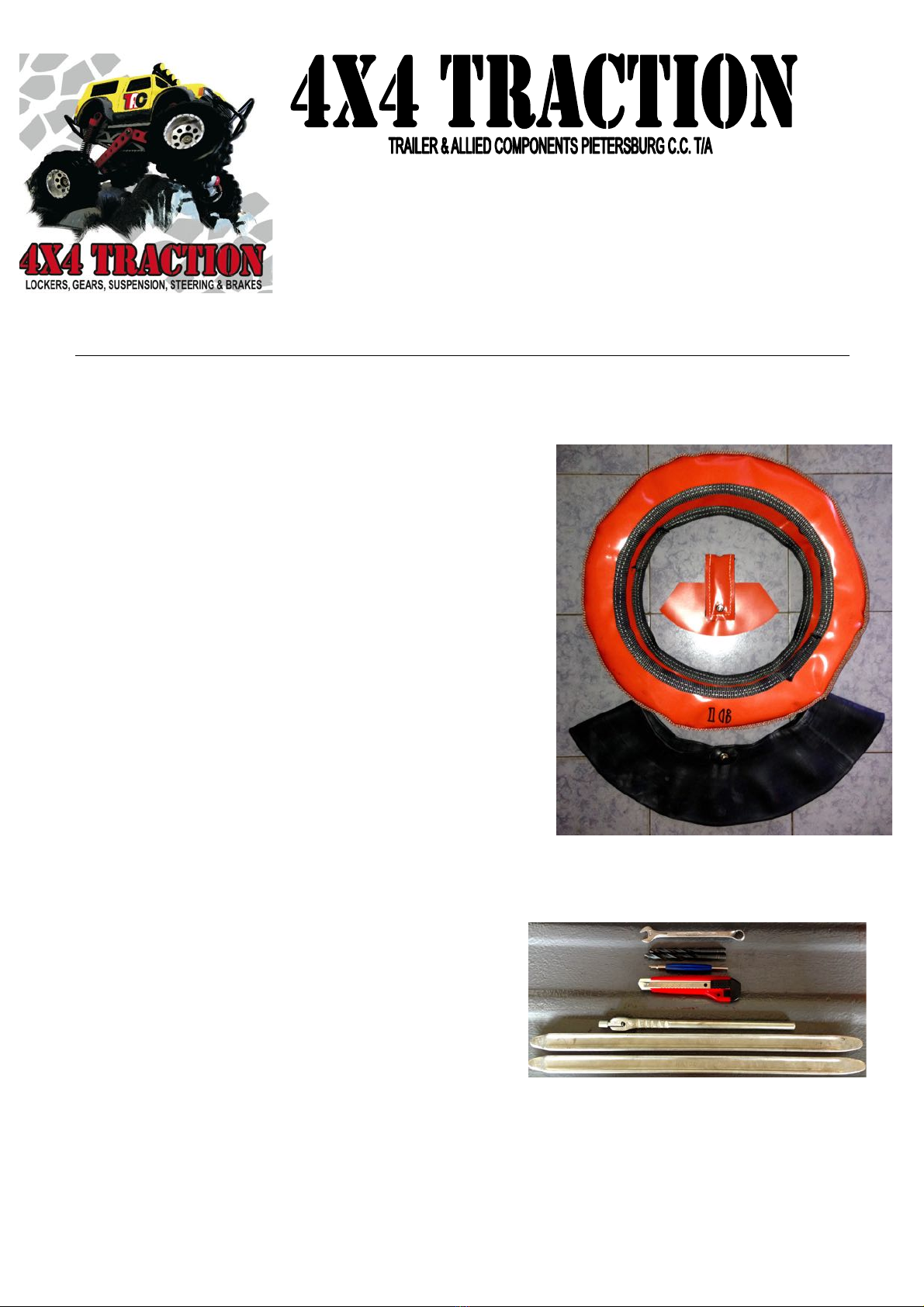
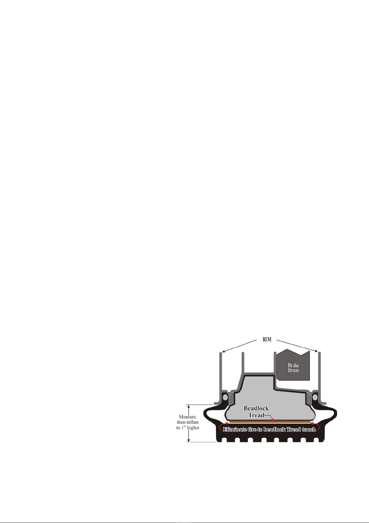
BEADLOCK PREPARATION
Using the powder supplied, generously “lubricate” 100% of the tube,
inside the casing and the inside of the rim. Both the inside and
outside of each beadlock bead must be dusted completely. The
lubricating powder makes it easier to move the tube within the
casing and for the beads to migrate to the correct position when
finally inflated.
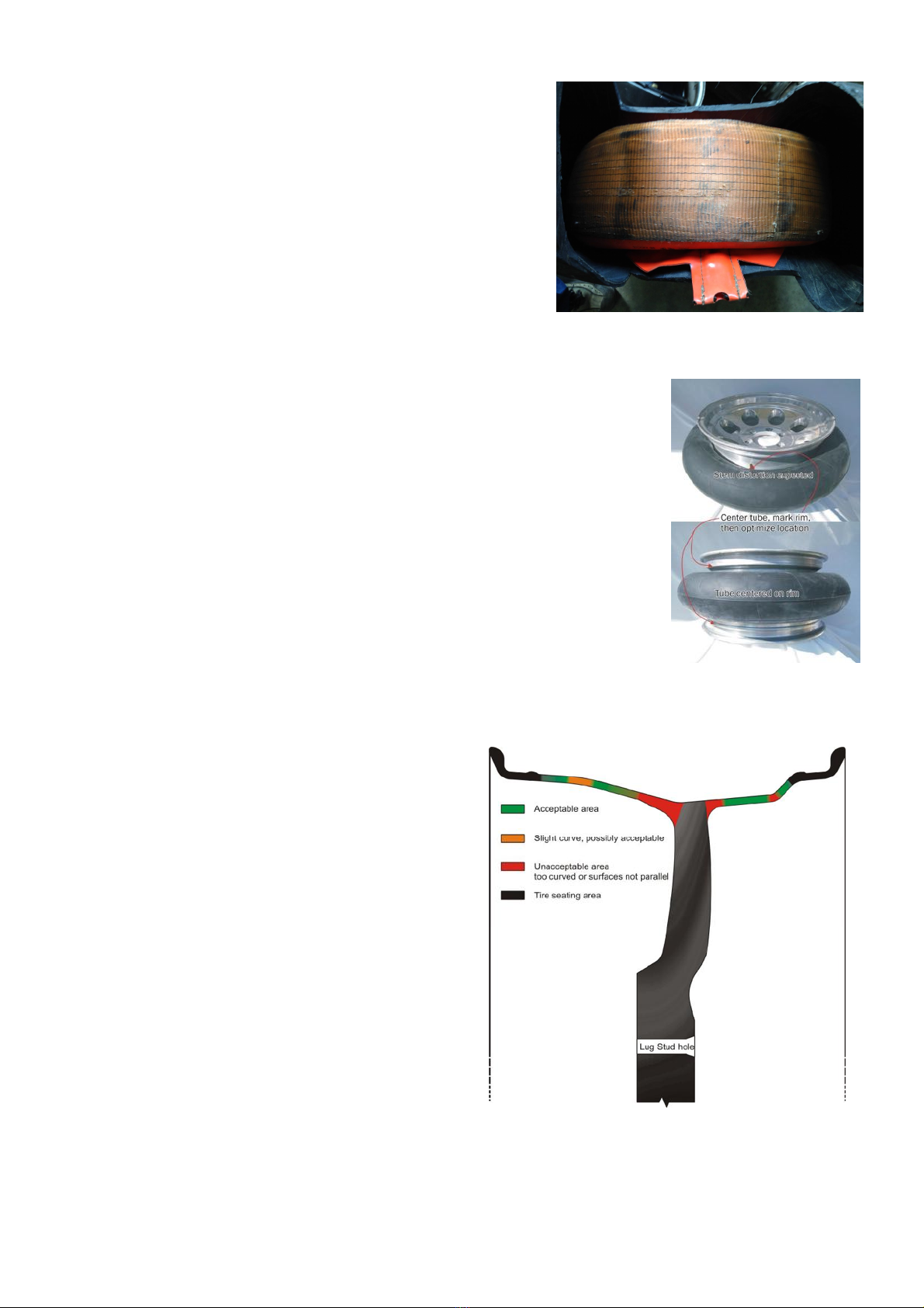
installation
1) Locate position for the tube valve
stem hole: The beadlock tube valve stem
hole should be 150 to 200 mm (5.905 to
7.874”) clockwise from the standard valve
stem hole and as near to the center of the
rim as practical without interfering with the
brakes and associated components if the
tube valve stem is located inboard/brake
side of the rim. Ensure that the proposed
inside and outside rim tube valve stem
hole surfaces are flat, parallel (to
accommodate both tube valve stem
O-rings) and less than 13mm (0.519”)
thick. (If your new Staun Internal Beadlocks
are being fitted to Staun manufactured
rims, the tube valve stem hole has been
predrilled. Proceed to step 3).
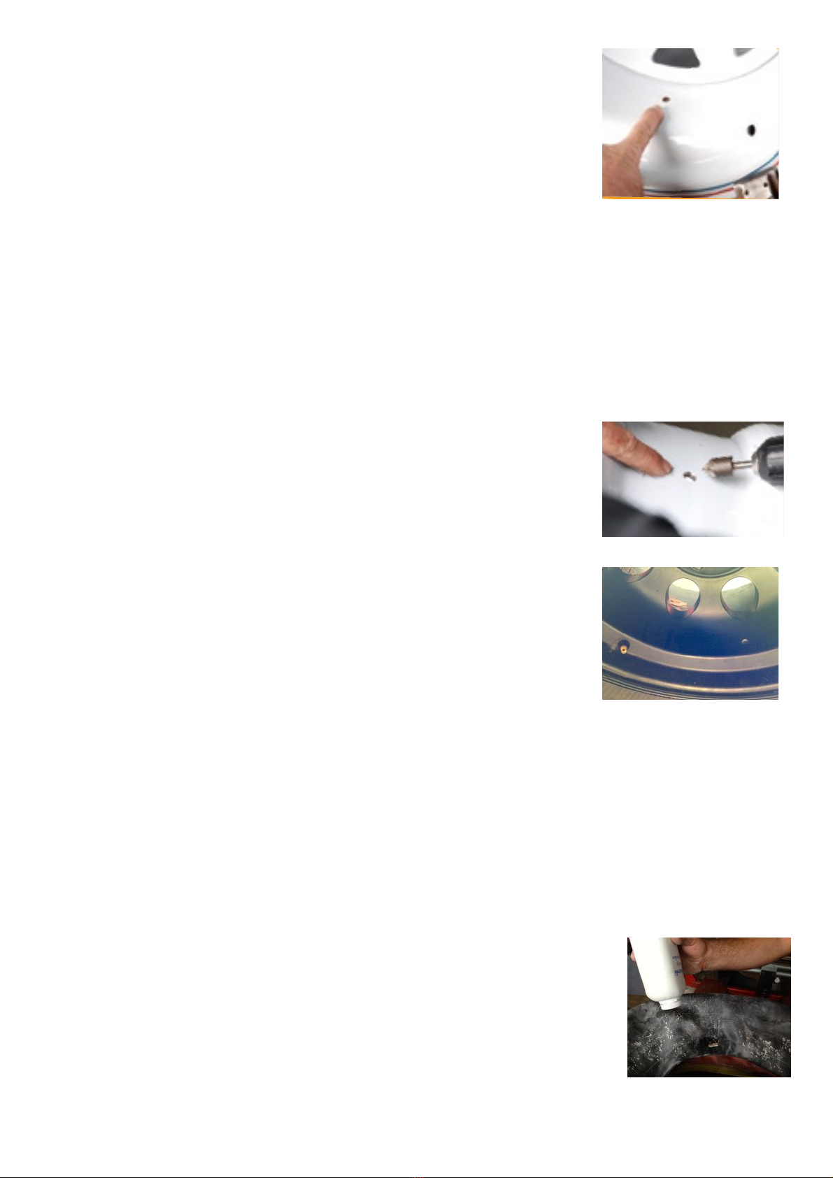
2) Drill and chamfer the tube valve
stem hole: Drill an 8 mm (0.315”) hole at
the chosen position. Chamfer the drop
center side of this hole to receive the
inner O-ring. The chamfer face should
be 2 to 3 mm (0.079 to 0.118”) wide. A
screw countersinking tool at slow rotating
speed is best to make the chamfer. Clean
all, metal chips off the rims, all beadlock
components and from within the tyres.
Chips can cause tube failure.
4
2
1
5
6
7
3) Prepare the rims: The rims should be
clean and free from all rough edges to
ensure that the tube is not damaged during
installation. All rust and labels, and their
adhesive should be removed from the rims.
4) Prepare the tyres: The inside edge of
the tyre bead should be checked for sharp
edges and buffed smooth as necessary.
This is particularly true of tyres 36 inches
and larger. This is mandatory for all tyres
with beads greater than 16 mm (0.629”)
regardless of diameter.
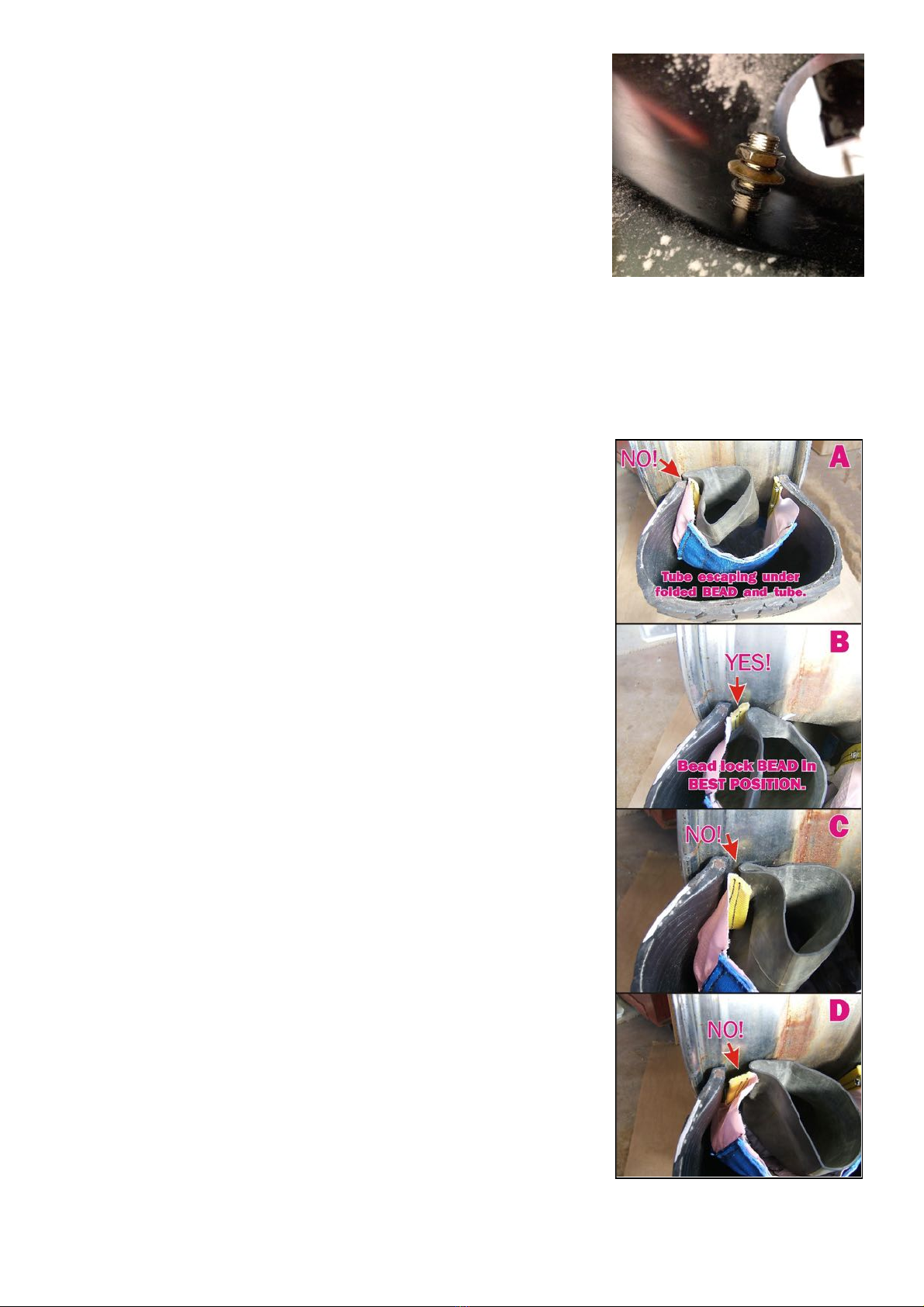
5) Powder all components: Powder
the beadlock cap, tube, air channel and
the rims’ drop center. Pay particular
attention to the inside and outside of both
beadlock beads (the black webbing at the
ID of the cap).
6) Contour the air channel: Select the
proper size rubber grommet for your rims’
tyre valve stem holes and discard the other.
Temporarily, and without force, hold an air
channel up to the existing valve stem hole
noting the shape necessary to fit to the
inside of the rim assuming the tyre bead is
in position. Without using the metal portion,
bend/pre-contour the air channels to the
shape if necessary. Set these aside for
step 12.
7) Mount the first tyre bead: Mount the
first tyre bead as normal. A Windex-like
product is recommended in place of
conventional tyre lubricants. This ensures
that if rewetted in actual use, the rim will not
spin within the tyre.
installation
1) Locate position for the tube valve
stem hole: The beadlock tube valve stem
hole should be 150 to 200 mm (5.905 to
7.874”) clockwise from the standard valve
stem hole and as near to the center of the
rim as practical without interfering with the
brakes and associated components if the
tube valve stem is located inboard/brake
side of the rim. Ensure that the proposed
inside and outside rim tube valve stem
hole surfaces are flat, parallel (to
accommodate both tube valve stem
O-rings) and less than 13mm (0.519”)
thick. (If your new Staun Internal Beadlocks
are being fitted to Staun manufactured
rims, the tube valve stem hole has been
predrilled. Proceed to step 3).
2) Drill and chamfer the tube valve
stem hole: Drill an 8 mm (0.315”) hole at
the chosen position. Chamfer the drop
center side of this hole to receive the
inner O-ring. The chamfer face should
be 2 to 3 mm (0.079 to 0.118”) wide. A
screw countersinking tool at slow rotating
speed is best to make the chamfer. Clean
all, metal chips off the rims, all beadlock
components and from within the tyres.
Chips can cause tube failure.
4
2
1
5
6
7
3) Prepare the rims: The rims should be
clean and free from all rough edges to
ensure that the tube is not damaged during
installation. All rust and labels, and their
adhesive should be removed from the rims.
4) Prepare the tyres: The inside edge of
the tyre bead should be checked for sharp
edges and buffed smooth as necessary.
This is particularly true of tyres 36 inches
and larger. This is mandatory for all tyres
with beads greater than 16 mm (0.629”)
regardless of diameter.
5) Powder all components: Powder
the beadlock cap, tube, air channel and
the rims’ drop center. Pay particular
attention to the inside and outside of both
beadlock beads (the black webbing at the
ID of the cap).
6) Contour the air channel: Select the
proper size rubber grommet for your rims’
tyre valve stem holes and discard the other.
Temporarily, and without force, hold an air
channel up to the existing valve stem hole
noting the shape necessary to fit to the
inside of the rim assuming the tyre bead is
in position. Without using the metal portion,
bend/pre-contour the air channels to the
shape if necessary. Set these aside for
step 12.
7) Mount the first tyre bead: Mount the
first tyre bead as normal. A Windex-like
product is recommended in place of
conventional tyre lubricants. This ensures
that if rewetted in actual use, the rim will not
spin within the tyre.