7starlake ROC286AA User manual

ROC286AA
MIL-STD Rugged Computer
User’s Manual
User’s Manual
Revision Date: OCT.26.2020

ROC286AAUser’s Manual
Revision Date:OCT.26.2020
1
Safety Information
Electrical safety
To prevent electrical shock hazard, disconnect the power cable from the electrical outlet before
relocating the system.
When adding or removing devices to or from the system, ensure that the power cables for the
devices are unplugged before the signal cables are connected. If possible, disconnect all power cables
from the existing system before you add a device.
Before connecting or removing signal cables from the motherboard, ensure that all power cables are
unplugged.
Seek professional assistance before using an adapter or extension cord. These devices could interrupt
the grounding circuit.
Make sure that your power supply is set to the correct voltage in your area.
If you are not sure about the voltage of the electrical outlet you are using, contact your local power
company.
If the power supply is broken, do not try to fix it by yourself. Contact a qualified service technician or
your local distributor.
Operation safety
Before installing the motherboard and adding devices on it, carefully read all the manuals that came
with the package.
Before using the product, make sure all cables are correctly connected and the power cables are not
damaged. If you detect any damage, contact your dealer immediately.
To avoid short circuits, keep paper clips, screws, and staples away from connectors, slots, sockets and
circuitry.
Avoid dust, humidity, and temperature extremes. Do not place the product in any area where it may
become wet.
Place the product on a stable surface.
If you encounter any technical problems with the product, contact your local distributor
Statement
All rights reserved. No part of this publication may be reproduced in any form or by any means,
without prior written permission from the publisher.
All trademarks are the properties of the respective owners.
All product specifications are subject to change without prior notice

2
Revision History
Revision
Date (yyyy/mm/dd)
Changes
Version 1.0
2020/10/26
Initial release
Packing list
□ 19” 1U Rack-mount Intel® Q370 Fanless Rugged System
□ Accessories
Ordering Information
ROC286AAUser’s Manual
Revision Date:OCT.26.2020
ROC286AA-ET
19” 1U Rack-mount Rugged Fanless System with 8th/9th Processor (up to 65W), Intel® UHD Graphics
630 with 3 DisplayPort, 1 x PCIe x16, 1 x M.2, 9~36V DC-in *2 , Operating Temp. -20~+60°C
ROC286AA-UT
19” 1U Rack-mount Rugged Fanless System with 8th/9th Processor (up to 65W), Intel® UHD Graphics
630 with 3 DisplayPort, 1 x PCIe x16, 1 x M.2, 9~36V DC-in *2 , AC-in, Operating Temp. -30~+70°C

3
Table of contents
Safety Information ............................................................................................................................................. 1
Electrical safety .............................................................................................................................................. 1
Operation safety ............................................................................................................................................ 1
Statement ...................................................................................................................................................... 1
Revision History.................................................................................................................................................. 2
Packing list.......................................................................................................................................................... 2
Ordering Information ......................................................................................................................................... 2
Chapter 1: Product Introduction ........................................................................................................................ 5
1-1 Key Features...................................................................................................................................... 5
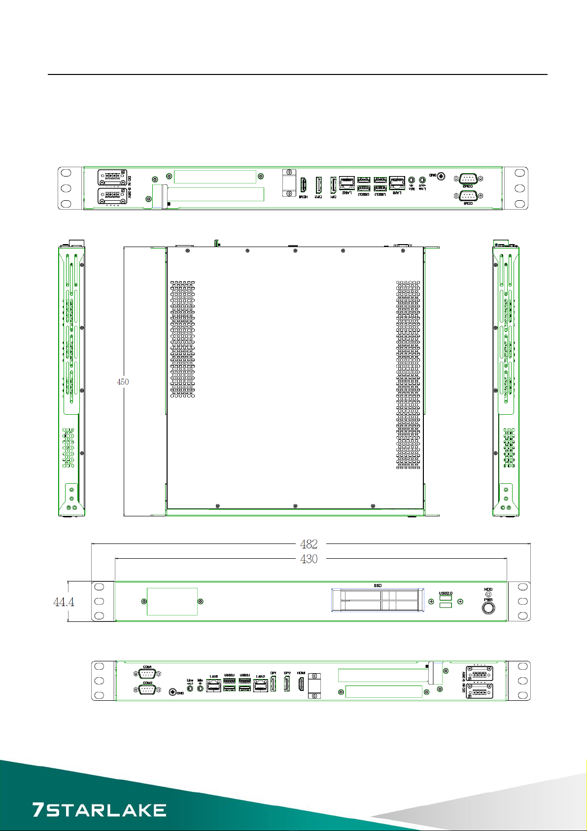
1.2 Mechanical Dimensions ........................................................................................................................ 7
1.3 Panel Component..................................................................................................................................... 7
1.4 Rear Panel Components ........................................................................................................................... 8
Chapter 2: Jumpers and Connectors Locations .................................................................................................. 9
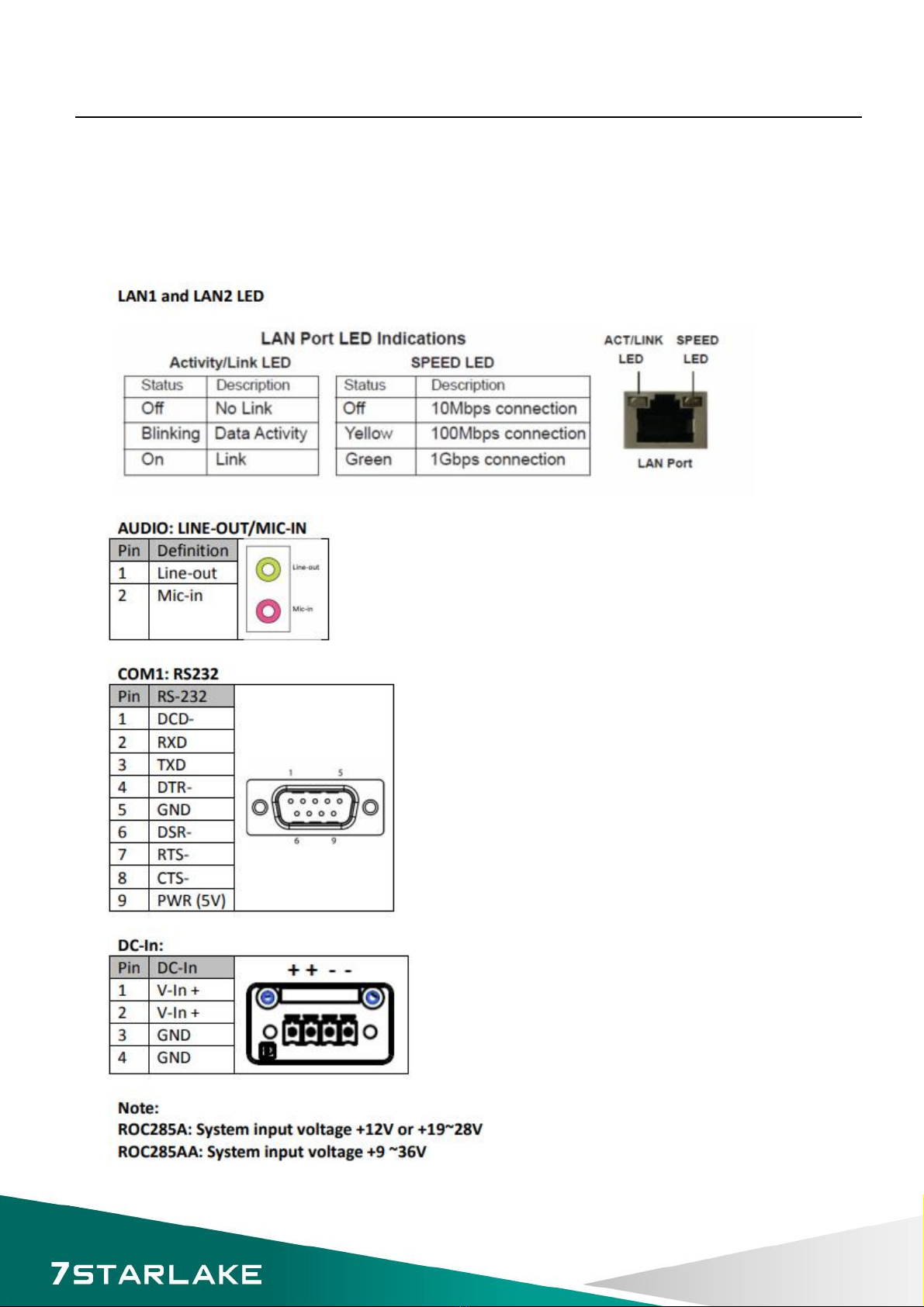
2.1 Rear Panel Connector Pin Definitions ...................................................................................................... 9
Chapter 3 Getting Started ............................................................................................................................. 10
Chapter 4: AMI BIOS UTILITY ............................................................................................................................ 11
4.1 Starting................................................................................................................................................... 11
4.2 Navigation Keys ...................................................................................................................................... 11
4.3 Main ....................................................................................................................................................... 12
4.4 Advanced ............................................................................................................................................... 13
4.4.2 CPU Configuration ........................................................................................................................... 14
4.4.3 ACPI Setting ..................................................................................................................................... 15
4.4.4 Smart Setting ................................................................................................................................... 15
4.4.5 F81866 Super IO Configuration ....................................................................................................... 16
4.4.6 Hardware Monitor ........................................................................................................................... 17
4.4.7 Platform Function ............................................................................................................................ 18
ROC286AAUser’s Manual
Revision Date:OCT.26.2020

ROC285A User’s Manual
Revision Date:Dec. 06. 2019
4
4.5 Chipset Menu ......................................................................................................................................... 22
4.5.1 System Agent (SA) Configuration..................................................................................................... 23
4.5.2 PCH-IO Configuration ...................................................................................................................... 25
4.6 Security Menu ........................................................................................................................................ 29
4.7 Boot Menu ............................................................................................................................................. 30
4.8 Save & Exit ............................................................................................................................................. 31

5
Chapter 1: Product Introduction
1-1 Key Features
ROC286AAUser’s Manual
Revision Date:OCT.26.2020
System
CPU 8th/9th Processor (up to 65W)
Chipset Intel® Q370 Chipset
Memory type 2 x DDR4 SO DIMM up to 64 GB
Storage Device 2 x SATAIII, 2.5” SSD
Storage
Display Port Resolution up to 4096 x 2304 60@Hz
HDD/SDD 2 x 2.5” SATA HDD/SSD easy swap tray
Ethernet
Ethernet Intel® I210 & I219LM GbE LAN (support 10/100/1000 Mbps for x2 RJ45 ports)
Rear I/O
Display Port 2 x DP, 1x HDMI
Ethernet 2 x RJ45 Intel® I210 & I219LM GbE LAN (support 10/100/1000 Mbps)
Audio 1xLine-Out;1xMic-IN
COM 2 x RS232
USB Port 4 x USB 3.1(10Gb/s)
DC-IN 2 X 4P Terminal Block
Front I/O
Button 1 x Power Button w/Indicator LED
Indicator LED HDD
USB Port 2 x USB 2.0
Easy Swap SSD Tray 2
Power Requirement
Power Input 9~36V DC IN
Applications, Operating System
Applications Commercial and Industrial Platforms, Embedded Computing, Process

6
ROC286AAUser’s Manual
Revision Date:OCT.26.2020
Control
Intelligent Automation and manufacturing applications
Operating System Windows 10 64Bit
Ubuntu13.04, Ubuntu13.10, Ubuntu14.04, Fedora 20
Physical
Dimension (W x D x H) 482 x450 x 44.4 mm
Weight 8.92Kg
Chassis SECC
Heatsink Aluminum Alloy, Corrosion Resistant
Finish Anodic aluminum oxide
Environmental
Green Product RoHS compliance
Operating
Temperature
w/o Graphic Card (ET: -20 to 60°C; UT: -30 to 70°C) ; w/Graphic Card (0 to
50°C)
Storage Temperature -40 to 85°C
Relative Humidity 5% to 95%, non-condensing
EMC CE and FCC compliance

7
1.2 Mechanical Dimensions
ROC286AAUser’s Manual
Revision Date:OCT.26.2020

9
ROC286AAUser’s Manual
Revision Date:OCT.26.2020
Chapter 2: Jumpers and Connectors Locations
2.1 Rear Panel Connector Pin Definitions

10
Chapter 3 Getting Started
ROC286AAUser’s Manual
Revision Date:OCT.26.2020

11
Chapter 4: AMI BIOS UTILITY
This chapter provides users with detailed descriptions on how to set up a basic system configuration
through the AMI BIOS setup utility.
4.1 Starting
To enter the setup screens, perform the following steps:
Turn on the computer and press the <Del> key immediately.
After the <Del> key is pressed, the main BIOS setup menu displays. Other setup screens can be
accessed from the main BIOS setup menu, such as the Chipset and Power menus.
4.2 Navigation Keys
The BIOS setup/utility uses a key-based navigation system called hot keys. Most of the BIOS setup
utility hot keys can be used at any time during the setup navigation process.
Some of the hot keys are <F1>, <F10>, <Enter>, <ESC>, and <Arrow> keys.
ROC286AAUser’s Manual
Revision Date:OCT.26.2020

12
4.3 Main
ROC286AAUser’s Manual
Revision Date:OCT.26.2020

13
4.4 Advanced
ROC286AAUser’s Manual
Revision Date:OCT.26.2020

14
4.4.2 CPU Configuration
ROC286AAUser’s Manual
Revision Date:OCT.26.2020

15
4.4.3 ACPI Setting
4.4.4 Smart Setting
ROC286AAUser’s Manual
Revision Date:OCT.26.2020

16
4.4.5 F81866 Super IO Configuration
ROC286AAUser’s Manual
Revision Date:OCT.26.2020

17
4.4.6 Hardware Monitor
4.4.6.1 Smart Fan Mode Configuration
ROC286AAUser’s Manual
Revision Date:OCT.26.2020

18
4.4.7 Platform Function
ROC286AAUser’s Manual
Revision Date:OCT.26.2020

19
4.4.8 Serial Consolr Redirection
ROC286AAUser’s Manual
Revision Date:OCT.26.2020

20
4.4.9 NVMe Configuration
ROC286AAUser’s Manual
Revision Date:OCT.26.2020
Table of contents
Other 7starlake Desktop manuals
Popular Desktop manuals by other brands

Acer
Acer Veriton M420 Service guide

Digital Equipment
Digital Equipment DEC 3000 500X AXP owner's guide

Fujitsu
Fujitsu DESKPOWER 6000 Seriesl DESKPOWER 6000 SD... user manual

HP
HP Compaq Presario Getting started

Advantech
Advantech AWS-8248 user manual

CTC Parker Automation
CTC Parker Automation PC9 Replacement

Advantech
Advantech ARK-5420 Series user manual

Groz
Groz MTB-12 instruction manual

Compaq
Compaq Compaq Presario 7400 Series Maintenance and service guide

Panasonic
Panasonic FZ-M1 Series operating instructions

Sony
Sony VPCL112GX - Vaio L Series All-in-one Touch... Specifications

Lenovo
Lenovo ThinkCentre M58e Uživatelská příručka