7th Sense Medialon Showmaster Mini User manual

M569-3
Medialon Showmaster
Hardware Manual
User Reference

Trademark Information
Medialon is a trademark of 7thSense Design Ltd. Product or company names that mentioned in
7thSense Design Ltd publications are tradenames or trademarks of their respective owners, and
such trademarks may also be registered in their respective countries.
Copyright Information
All Rights Reserved. This document is copyrighted © by 7thSense Design Ltd and shall not be
reproduced or copied without express written authorization from 7thSense Design Ltd.
The information in this document is subject to change without notice. 7thSense Design Ltd
assumes no responsibility for errors, and/or omissions contained in this information.
Document Revision
Date Document
edition
Software version Revision details Author/Editor
May 2020 M569-1 Medialon Manager 6.7
Medialon Showmaster Editor 2.7.0
Eric Cantrell
Andie Davidson (ed)
August 2022 M569-2 Medialon Manager 7
Medialon Showmaster Editor 2.7.0
Reformatted Andie Davidson (ed)
June 2023 M569-3 Medialon Manager 7.1 Editor software deprecated,
superseded by Manager
Dominic Turpin
M569-3

Medialon Showmaster User Manual p 1 of 42
M569-3 | June 2023
Contents
1 About this Manual ................................................................................................................... 3
1.1 Prerequisites.......................................................................................................................................... 3
1.2 Objective of this Manual...................................................................................................................... 3
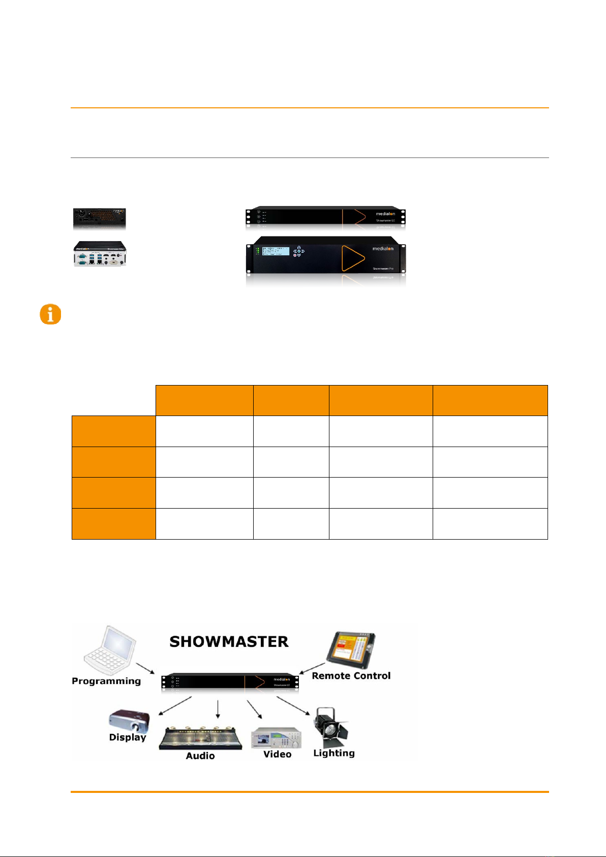
2 Showmaster Overview............................................................................................................. 4
2.1 Embedded Show Controllers.............................................................................................................. 4
2.1.1 Showmaster Architecture ..................................................................................................... 7
2.1.2 Medialon Showmaster Modes ............................................................................................. 8
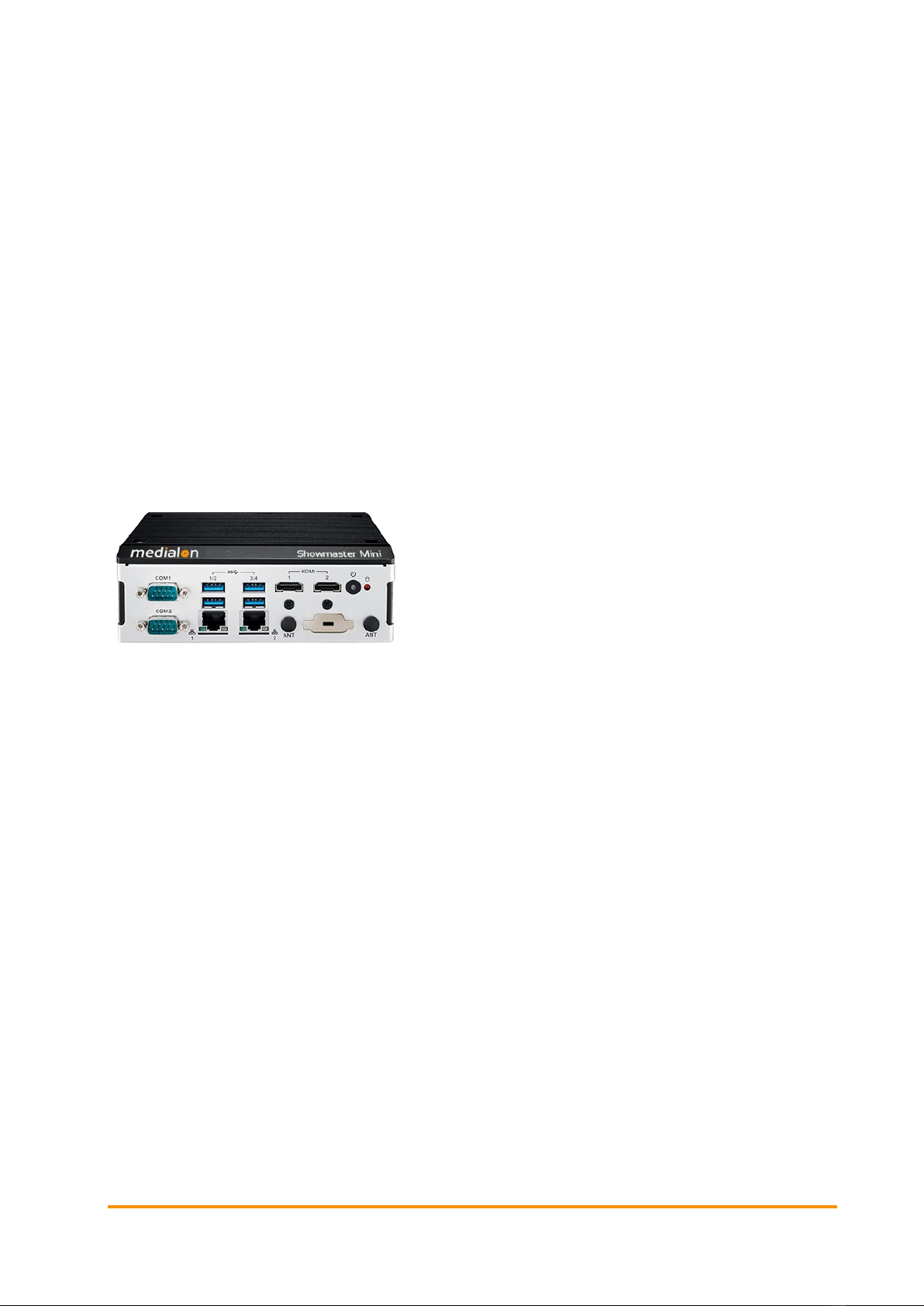
2.2 Showmaster Mini Description............................................................................................................ 8
2.2.1 Contents of the Package....................................................................................................... 8
2.2.2 Getting Started........................................................................................................................ 8
2.2.3 Front Panel Controls .............................................................................................................. 9
2.2.4 Side Panel................................................................................................................................. 9
2.2.5 Mounting .................................................................................................................................. 9
2.2.6 Technical Specifications ....................................................................................................... 9
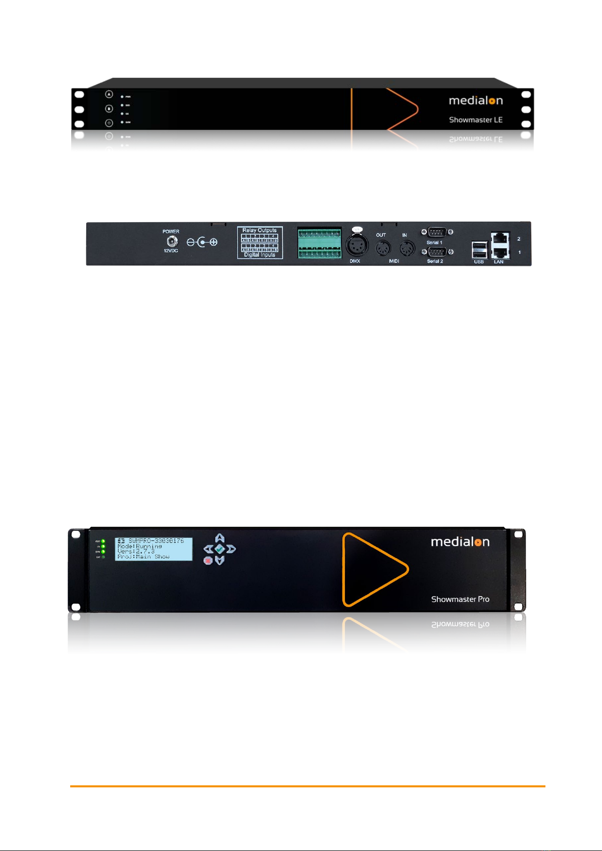
2.3 Showmaster LE Description .............................................................................................................11
2.3.1 Contents of the Package.....................................................................................................11
2.3.2 Getting Started......................................................................................................................11
2.3.3 Front Panel Controls ............................................................................................................12
2.3.4 Rear Panel..............................................................................................................................13
2.3.5 Rack Mount............................................................................................................................15
2.3.6 Technical Specifications .....................................................................................................16
2.4 Showmaster Pro Description............................................................................................................19
2.4.1 Contents of the Package.....................................................................................................19
2.4.2 First Start................................................................................................................................19
2.4.3 Front Panel Controls ............................................................................................................19
2.4.4 Rear Panel..............................................................................................................................22
2.4.5 Rack Mount............................................................................................................................26
2.4.6 Technical Specifications .....................................................................................................27
2.5 Showmaster Go Description.............................................................................................................31
2.5.1 Contents of the Package.....................................................................................................31
2.5.2 Getting Started......................................................................................................................31
2.5.3 Front Panel.............................................................................................................................31

Medialon Showmaster User Manual p 2 of 42
M569-3 | June 2023
2.5.4 Rear Panel..............................................................................................................................32
2.5.5 Mounting ................................................................................................................................33
2.5.6 Technical Specifications .....................................................................................................33
2.5.7 Environment...........................................................................................................................34
2.5.8 Maintenance..........................................................................................................................35
2.6 Disposal Information: All Showmaster Devices............................................................................35
3 Showmaster Maintenance..................................................................................................... 37
3.1 Showmaster Troubleshooting..........................................................................................................37
Contact Us ............................................................................................................................... 38

Medialon Showmaster User Manual p 3 of 42
M569-3 | June 2023
1About this Manual
This manual is written for professional users: show technicians, freelancers and end user
technicians who are responsible for installing and running Medialon Showmaster show
controllers in live events or permanent installations.
This edition relates to Medialon Manager 7.1 running on Showmaster devices and no longer
running Showmaster Editor. For Showmaster Editor, please see the previous edition: M569-2.
Important: please read
•M562 Medialon Safety Instructions for installation, use and service
•M561 End User’s License Agreement for Medialon Software and Plug-Ins. Warranty Terms and
Conditions for Medialon Hardware
For Medialon show control software, please refer to:
•M515 Medialon Control Systems Manual (includes appendix on converting Editor v.2 files)
•M816 Medialon Manager Web Interface
1.1 Prerequisites
This manual assumes the following prerequisites:
•Proficiency using Windows interface
•General knowledge of computer hardware
•General knowledge of control protocols: DMX 512, MIDI, Serial, Timecode
•General knowledge in audio-visual: Video, Video processing, Audio, Lighting, Machinery
•General knowledge in show structure
1.2 Objective of this Manual
After reading this manual, you will be able to:
•Describe the features of Medialon show control hardware
•Set up hardware required for a Show Control installation using Medialon show control
hardware

Medialon Showmaster User Manual p 4 of 42
M569-3 | June 2023
2Showmaster Overview
2.1 Embedded Show Controllers
Medialon Control System brings the power of Medialon Manager, award-winning Show Control
software, in a rugged and compact hardware design.
Showmaster Go Showmaster LE
Showmaster Mini Showmaster Pro
The Showmaster range includes products that are managed in different ways. All models run
Medialon Manager on the Showmaster hardware. Programming is done directly on the
Showmaster Mini or Showmaster Go hardware. This is a key difference. Programming can be
done directly on the Showmaster LE and Pro as well as offline (without the ability to run or debug
the project) using Medialon Manager set in the appropriate mode.
Programming
Software
Number of
Timelines
Number of Web Panel
Connections Number of Devices
Showmaster Mini Medialon Manager
for Showmaster Mini
0 1 20, upgradable in batches
of 10 to max of 50
Showmaster LE Medialon Manager
for Showmaster LE
1 3 Unlimited
Showmaster Pro Medialon Manager
for Showmaster Pro
Unlimited 10 Unlimited
Showmaster Go Medialon Manager
Lite or Pro
1 or Unlimited 2 or 10, upgradable in
batches of 10
Unlimited
Showmaster LE and Showmaster Pro use a run-time version of Medialon Manager software. A
timeline show is created by connecting a computer / laptop to Showmaster via Ethernet, authoring
the project either directly on the Showmaster using a remote connection or offline, and then
transferring the finalised project.

Showmaster Overview
Medialon Showmaster User Manual p 5 of 42
M569-3 | June 2023
Medialon Showmaster benefits from the extensive Medialon device plug-in library for connectivity
with a wide range of audio-visual equipment.
Showmaster projects can be created directly on the Showmaster via a connection through either
RDP or TeamViewer, as well as offline using Medialon Manager. In the latter case, the resulting
project file must be deployed to the Showmaster’s hard drive either manually or through the
Showmaster’s web interface (Pro or LE models only).
Showmaster Mini
Showmaster Mini is a capable and flexible device is suited to simple AV control applications and
installation types. Its ruggedized, fanless, small form factor makes it easy to mount where AV
racks are not suitable. Showmaster Mini carries a reduced-feature version of Medialon Manager
show control software, making it a low-cost solution that still carries the power, flexibility, and
ease of use Medialon is known for. Designed for less demanding applications, it starts with a 20-
device limitation, expandable in 10-device batches up to a max of 50 devices. This AV device
controller runs Medialon Manager V6 and V7 for Showmaster Mini for step-based tasks only.
The connectors for Showmaster Mini are all on the front of the unit, as it is meant to be mounted
vertically on a DIN rail. It includes two Serial ports, four USB 3.0 ports, two HDMI ports (for Local
Panels and programming), two 10/100/1000 Base-T Ethernet ports, and the power button.
Showmaster Mini runs Windows 10 IoT Enterprise LTSC and includes Medialon Manager for
Showmaster Mini software for programming and show execution.
Showmaster LE
Showmaster LE is an all-in-one Embedded Show Controller fitted with all necessary show protocol
interfaces. It controls and synchronizes dimmers, lighting desks, video projectors, video servers,
sound processors etc. Showmaster LE also provides digital I/O.
Its editing software, Medialon Manager 7.1, embeds most of the features of our award-winning
technology such as devices synchronization and logical programming as well as real time testing.
It allows programming of one show at a time, up to 3 Web Panels but does not support 3rd party
extension interfaces.
Medialon Showmaster LE is a 1 U, full 19” rack-mountable machine; the front panel consists of
function buttons and status LEDs.

Showmaster Overview
Medialon Showmaster User Manual p 6 of 42
M569-3 | June 2023
The rear panel hosts two 10/100/1000 Base-T Ethernet interfaces, digital I/O connections, serial
ports, a DMX port, and MIDI ports.
Medialon Showmaster LE operates on an embedded operating system (OS) and is programmed
with Medialon Manager 7.1 software.
Showmaster Pro
Showmaster Pro is an all-in-one embedded Show Controller fitted with all necessary show protocol
interfaces. It controls and synchronizes dimmers, lighting desks, video projectors, video servers,
sound processors etc. Showmaster Pro also provides digital I/O and balanced timecode
input/output with video reference.
Its editing software, Medialon Manager 7.1, embeds most of the features of our award-winning
technology such as devices synchronization and logical programming as well as real time testing.
It supports multiple timeline, 3rd party interfaces, up to 10 Web Panels and signal recording.
Medialon Showmaster Pro is a 2U, full 19” rack-mountable machine; the front panel consists of an
LCD display, function buttons and status LEDs. (Mk 2 illustrated).
The rear panel hosts two 10/100/1000 Base-T Ethernet interfaces, digital I/O, serial ports, DMX
ports, MIDI ports and timecode input and output ports.

Showmaster Overview
Medialon Showmaster User Manual p 7 of 42
M569-3 | June 2023
Medialon Showmaster Pro operates on an embedded operating system (OS) and is programmed
with Medialon Manager 7.1 software.
Showmaster Go
Showmaster Go is the top of the line Medialon show control product, running Medialon Manager
V6 and V7 software and MAS Pro Dante software on the same compact, ruggedized hardware. It
is intended to be mounted on things that move: ride vehicles, parade floats, tour buses, trams,
show barges, etc.
It can be mounted in a 1U rack mount (three can fit side by side in 1U of rack space), or it can be
mounted in a shock mount carrier for high vibration/high shock environments. The front panel
includes the power button, a USB 2.0 type A connector, and a USB 3.0 type C connector.
The rear panel has four DisplayPort outputs (for Local Panels), a GPIO port with 3 software-
configurable channels of Input or Output, two 10/100/1000 Base-T Ethernet ports, and two USB
2.0 type A ports.
Showmaster Go runs Windows 10 IoT Enterprise LTSC and includes Medialon Manager (Lite or
Pro, depending on licensing) and MAS Pro software (licensed for 16, 32 or 64 channels of Dante
output).
2.1.1 Showmaster Architecture
The remainder of this section is specific to the Showmaster Pro and Showmaster LE architecture,
since it differs from Medialon Manager, documented elsewhere in this manual. The following
sections only apply to Showmaster LE and Showmaster Pro.

Showmaster Overview
Medialon Showmaster User Manual p 8 of 42
M569-3 | June 2023
2.1.2 Medialon Showmaster Modes
Showmaster LE/Pro switches between different modes to run and to program.
Running or Normal Mode
This is the default mode of Medialon Showmaster LE/Pro. At startup, Showmaster LE/Pro uses
its locally connected resources and runs the show.
•Device Commands are executed when the Timeline runs.
•The Devices send command orders using a Medialon plug-in (MxM) through the appropriate
resources (MRC) to connected machines.
Programming Mode
Programming is done in Stop mode using either an offline version of Medialon Manager that is
set to the appropriate Showmaster model’s mode, or directly on the device via a remote connection.
2.2 Showmaster Mini Description
2.2.1 Contents of the Package
The Medialon Showmaster Mini Package includes:
•Medialon Showmaster Mini
•Power adaptor
2.2.2 Getting Started
Showmaster Mini runs a version of Medialon Manager, and programming can be done directly on
the hardware.

Showmaster Overview
Medialon Showmaster User Manual p 9 of 42
M569-3 | June 2023
2.2.3 Front Panel Controls
Power button
Press to power on Showmaster Mini. The orange LED indicates the power state.
•2 × Serial, COM 1 and COM 2
•4 × USB 3.0
•2 × RJ45 10/100/1000 base-T Ethernet
•2 × HDMI UHD
2.2.4 Side Panel
The image below shows the side panel of Medialon Showmaster Mini. This has the Phoenix DC
power connector and 3.5 mm mini-jack sockets for line out and mic in.
2.2.5 Mounting
The rear panel has 3 screw points for attaching a DIN-rail bracket for vertical mounting.
Alternatively, the unit can be wall mounted using two correct brackets, attached to left and right
sides at the lower two screw points on each side.
2.2.6 Technical Specifications
USB ports 4 × USB 3.0
Serial ports 2 × RS232
Video output 2 × HDMI UHD
Audio 1 × mic in, 1 × line out, 3.5 mm mini jack
Ethernet 2 × 10/100/1000 base-T
Storage 238 GB SSD

Showmaster Overview
Medialon Showmaster User Manual p 10 of 42
M569-3 | June 2023
Power connection 12-28 VDC 60 W (3 pin Phoenix connector)
Power consumption 7.6 W typical, 19 W max.
Mounting options DIN-rail/Wall Mount
Dimensions (W × D × H) 158 mm × 114 mm × 53.5 mm (6-1/4” × 4-1/2” × 2-1/8”)
Weight 1.2 kg (2.65 lbs)
Technical specifications are subject to change without prior notice. Please check
www.medialon.com for the latest information.
Environmental Specifications
Operating Temperature
•With industrial-grade SSD/mSATA: –30 ~ 70 °C (22 ~ 158 °F), with airflow rate = 0.7 m/sec
•With 2.5-inch hard disk: 0 ~ 45 °C (32 ~ 113 °F), with airflow rate = 0.7 m/sec
Relative Humidity
•95% @ 40 °C (non-condensing)
Storage Temperature
•-40 ~ 85 °C (–40 ~ 185 °F)
Vibration Tolerance
•When the system is equipped with an SSD/mSATA: 3 Grms, IEC 60068-2-64, random, 5 ~
500 Hz, 1 hr/axis, (x, y, z) 3 axes
Shock Tolerance
•When the system is equipped with an SSD/mSATA: 30 G, IEC 60068-2-27, half sine, 11 ms
duration
Safety Certification
•UL, CB, CCC, BSMI
EMC Certification
•CE, FCC, CCC, BSMI
Federal Communications Commission (FCC Statement)
This equipment has been tested and found to comply with the limits for a Class B digital device,
pursuant to part 15 of the FCC Rules. These limits are designed to provide reasonable protection
against harmful interference in residential installations. This equipment generates, uses, and can

Showmaster Overview
Medialon Showmaster User Manual p 11 of 42
M569-3 | June 2023
radiate radio frequency energy and, if not installed and used in accordance with the instructions,
may cause harmful interference to radio communications. However, there is no guarantee that
interference will not occur in a particular installation. If this equipment does cause harmful
interference to radio or television reception, which can be determined by turning the equipment
off and on, users are encouraged to try to correct the interference by one or more of the following
measures:
•Reorient or relocate the receiving antenna.
•Increase the separation between the equipment and receiver.
•Connect the equipment into an outlet on a circuit different from that to which the receiver is
connected.
•Consult your dealer or an experienced radio/TV technician for help.
For further technical information, please refer to the Advantech ARK-1220L user manual.
2.3 Showmaster LE Description
2.3.1 Contents of the Package
The Medialon Showmaster LE Package includes:
•Medialon Showmaster LE
•Power adaptor
2.3.2 Getting Started
Medialon Showmaster LE is designed as a stand-alone Show Controller.
Showmaster LE does not need a keyboard, mouse or screen to work.
Connect the power supply and press and hold the front button to start Showmaster LE.

Showmaster Overview
Medialon Showmaster User Manual p 12 of 42
M569-3 | June 2023
2.3.3 Front Panel Controls
Button Functions
A button
Not used.
B button
Not Used.
Power button
Press this button to power on Showmaster.
Press this button to power off (soft power) Medialon Showmaster.
LED Status Messages
Four LEDs give a quick overview of the main status of Medialon Showmaster.
PWR: Power LED
This LED lights red when Showmaster is powered on.
SSD: SSD LED
This LED blinks blue when Showmaster is reading or writing to its internal storage.
OS: Showmaster LED
This LED indicates the current status of Medialon Showmaster.
SHW: Project LED
This LED indicates the current status of the Medialon Showmaster Project.

Showmaster Overview
Medialon Showmaster User Manual p 13 of 42
M569-3 | June 2023
Status OS SHW
Default (Not Ready) State OFF OFF
Showmaster Starting Up / Shutting
Down Blink OFF
Showmaster Ready (OS) ON OFF
Showmaster Project Starting ON Blink
Showmaster in Running Mode ON ON
Showmaster in Programming Mode ON Blink Slow
License Missing Alternate Blink
IP Address Conflict Detected Pulse ×3 ON
2.3.4 Rear Panel
The image below shows the rear panel of Medialon Showmaster LE.
•[LAN] RJ45 Ethernet LAN connectors (10/100/1000 Base-T)
•[USB]: Not used (*)
•[Serial 1] Serial Port 1: Serial RS232 port
•[Serial 2] Serial Port 2: Serial RS232 port
•[MIDI] MIDI Port: MIDI Input and Output
•[DMX512] DMX Port: DMX512 Output
•[Relay Outputs] Digital Output Port: 4 relays 24 V 1 A Max
•[Digital Inputs] Digital Input Port: 4 contact closure input detection max 10 kΩ
•[POWER] Power Connector 12 VDC 5 A. See Power section for details.
(*) USB bottom port may be used for maintenance purposes (such as image updates/restoration),
top port is not used.

Showmaster Overview
Medialon Showmaster User Manual p 14 of 42
M569-3 | June 2023
Digital Input/Output Port Wiring
Digital Input Connector
Showmaster LE has four digital (contact closure) inputs.
Digital Inputs are connected to Showmaster LE via terminal block connectors.
Relay Output Connector
Showmaster LE has four relays. Relay outputs are connected to Showmaster LE via 4 terminal
block connectors.
MIDI Connection
Medialon Showmaster LE is provided with MIDI Input and Output port.
Pin Connection
1 NC
2 NC
3 Cable shield (output only)
4 +5 V DC (source)
5 MIDI Data (sink)
Input X A
SHOWMASTER
Input X B
Push Button
+
DC
−
Relay X A
SHOWMASTER
Relay X B
Indicator

Showmaster Overview
Medialon Showmaster User Manual p 15 of 42
M569-3 | June 2023
DMX Connection
Medialon Showmaster LE is provided with a DMX 512 output.
Pin Connection
1 Ground
2 Data –
3 Data +
4 NC
5 NC
Serial Connection
Medialon Showmaster LE is provided with 2 serial ports.
Showmaster LE is configured with DTE serial ports. Use a crossover (null modem) cable when
you want to connect to a computer.
2.3.5 Rack Mount
WARNING – The unit is intended to be rack-mounted as per applicable requirements so no
imbalance likely to occur to the internal components. Adequate clearance for airflow should be
provided on both sides so ambient temperature does not exceed the limit.
•Please refer to document: M562 Medialon Safety Instructions for installation, use and service.
Installation
NOTE You need a #2 Phillips screwdriver for rack mount installation. Complete the following
steps to mount devices in a rack:
•Remove the rack mount kit from the shipping carton. The kit contains two L-shaped mounting
brackets and four sink-head screws.
•Using a Phillips screwdriver, attach the mounting brackets to the sides of the device using four
sink-head screws.
•Using a Phillips screwdriver, mount the device in the rack using four rack-mounting screws.

Showmaster Overview
Medialon Showmaster User Manual p 16 of 42
M569-3 | June 2023
2.3.6 Technical Specifications
Network Connection
•Number: 2
•Connector: RJ45 female
•Interface: 10/100/1000 Mbps (1000 Base-T)
•Protocol: TCP/IP
•Addressing: Static IP or DHCP
USB Connections
•Number: 2
•Connector: USB slave socket
•Interface: USB 2.0
•USB Top Port: Not Used
•USB Bottom Port: May be used for maintenance purposes (such as image updates/restoration)
Serial Interfaces
•Number: 2
•Connector: 9-pin D-type Male
•Format: RS-232
Digital Interfaces
Isolated Inputs:
•Number: 4
•Mode: Contact closure
•Connector: terminal block
Relay Outputs:
•Number: 4 Relays
•Contact Type: Dry Contact
•Max. Switching Voltage: 24 V DC
•Max. Switching Current: 1 A
•Connector: terminal block

Showmaster Overview
Medialon Showmaster User Manual p 17 of 42
M569-3 | June 2023
DMX Interface
•Number: 1 DMX512 Output
•Connector: XLR 5 pin – type Female
MIDI Interface
1 MIDI Output / 1 MIDI Input
•Connector: MIDI DIN 5 pin – type Male
Physical
•Size Rack Mount (W ×D ×H): 18.75 ×10.25 ×1.75” (476 ×260 ×44.5 mm)
•Size Stand-alone (W ×D ×H): 17.38 ×10.25 ×1.75” (441 ×260 ×44.5 mm)
•Weight: 11 lbs (5 kg)
•Operating Temperature: 32°F – 104°F (0°C – 40°C)
•Storage Temperature: –4°F – 185°F (–20°C – 85°C)
•Operating Humidity: 10 – 80% RH Non-condensing
•Storage Humidity: 5 – 90% RH Non-condensing
•Operating Altitude: sea level to 2000 metres.
Power
•External Power Adapter EDACPOWER ELEC
•Model EA10683N-120
•AC Input 100-240 V – 2.0 A, 50-60 Hz
•DC Output 12 V DC 5 A
•Connector: DC-Jack
Approvals
•FCC 47 CFR Part 15 Subpart B
•ICES-003 Canada
•EN 55032
•IEC 61000-3-2 and IEC 61000-3-3
•EN 55024
•IEC-61000-4-2 and IEC-61000-4-3 and IEC-61000-4-4 and IEC-61000-4-5 and IEC-61000-4-6
and IEC- 61000-4-11

Showmaster Overview
Medialon Showmaster User Manual p 18 of 42
M569-3 | June 2023
•IEC/EN/UL 62368-1
•CSA C22.2#62368-1
•IEC 60950-1
Federal Communications Commission (FCC Statement)
This equipment has been tested and found to comply with the limits for a class A digital device,
pursuant to Part 15 of the FCC rules. These limits are designed to provide reasonable protection
against harmful interference when the equipment is operated in a commercial environment. This
equipment generates, uses, and can radiate radio frequency energy, and if not installed and used
in accordance with the instruction manual, may cause harmful interference to radio
communications. Operation of this equipment in a residential area may cause harmful
interference, in which case the user will be responsible for correcting any interference at their own
expense
Changes or modifications not expressly approved by the party responsible for compliance could
void the user’s authority to operate the equipment
FCC responsible:
7thSense Design Ltd
4207 Vineland Rd.
Suite M1
Orlando, FL 32811
USA
T: +1 407 505 5200
EMC notices
EN55032/CISPR32 Class A MME (MultiMedia Equipment)
Warning: This equipment is compliant with Class A of CISPR 32. In a residential environment this
equipment may cause radio interference.
GB/T 9254 Class A ITE (Information Technology Equipment)
Warning: This is a Class A product. In a domestic environment this product may cause radio
interference in which case the user may be required to take adequate measures.
Accessories
•Included: Power adaptor, rack mount brackets
This manual suits for next models
3
Other 7th Sense Recording Equipment manuals
Popular Recording Equipment manuals by other brands

Lutron Electronics
Lutron Electronics RadioTouch RTA-RS232 Setup and installation guide

Yamaha
Yamaha CDR-HD1500 quick start guide

ISOVOX
ISOVOX ISOVOX 2 Installation and user instructions

Yamaha
Yamaha TX1P operating manual

Hioki
Hioki Memory HiCorder MR6000 Quick start manual

FONESTAR
FONESTAR AIP-GO quick start guide