7th Sense Juggler 1 User manual

Juggler Pixel Processor
Operating Juggler 1
M611-1
User Guide

2
M611-1 Operating Juggler 1 Pixel Processor : User Guide © 2022 7thSense
The 7thsense logo, and various hardware and software product names are trademarks of 7thSense Design
Ltd. Product or company names that may be mentioned in 7thSense publications are tradenames or
trademarks of their respective owners, and such trademarks may also be registered in their respective
countries. Windows is a registered trademark of Microsoft Corporation in the United States and other
countries.
Operating Juggler 1 Pixel Processor : User Guide
Trademark Information
Copyright Information
All Rights Reserved. This document is copyrighted © by 7thSense Design Ltd and shall not be reproduced
or copied without express written authorisation from 7thSense Design Ltd.
The information in this document is subject to change without notice. 7thSense Design Ltd assumes no
responsibility for errors, and/or omissions contained in this information.
Printed: September 2022
This edition is for software version N/A
Document ref.: M611-1
7thSense Design LLC, Orlando7thSense Design LLC, Michigan
7thSense Design Ltd
E: info@7thsense.one
W: 7thsense.one
2 The Courtyard, Shoreham Road
Upper Beeding
Steyning
West Sussex
BN44 3TN
UK
T: +44 (0) 1903 812299
332 E Lincoln Ave
Suite 100
Royal Oak, MI 48067
USA
T: +1 248 599 2717
4207 Vineland Rd
Suite M1
Orlando, FL 32811
USA
T: +1 407 505 5200

3
M611-1 Operating Juggler 1 Pixel Processor : User Guide © 2022 7thSense
Contents
Introduction 4
Juggler and Compere 5
System Architecture 8
What Juggler Can Do 9
Front Panel: Controls 11
Front Panel Display 12
Set Juggler Static IP and Subnet 14
Rear Panel Connections 15
Input and Output Options 17
GPIO HD-BNC Ports 20
GPIO Genlock Example 21
Workflow: Physical Connections 24
Connect a Juggler Optical Data Bus 25
Connecting to a Network and Devices 28
Juggler Software and Firmware 29
Juggler Physical Specifications 31
Rack Mounting Jugglers 33
Juggler Care and Maintenance 34
Warranty, Support and Service 37
Regulatory Compliance 38
Document Information 39
40Index

4
M611-1 Operating Juggler 1 Pixel Processor : User Guide © 2022 7thSense
Introduction
Introduction
Juggler™ and Compere™ go together. Juggler is the hardware that processes the pixels and
Compere, like an event manager, is the control software and user interface that tells one or more
Jugglers what to do. Together, any range of digital inputs can be transformed and directed to an any
range of outputs, because Juggler modules can be daisy-chained on a data bus to expand inputs,
outputs and bandwidth as required. Compere does much more besides in its Visualise role (separate
licence), but this guide focuses on Juggler system set up.
For setting Juggler 1 systems up in Compere, see The Compere User Guide:
Ø
Compere 1.0-5 User Guide
Juggler is a highly modular FPGA-based pixel processor, providing the highest hardware performance
and efficiency, combined with ultimate connectivity. It is specified according to application, with a
very wide choice of input and output options: DisplayPort™ 1.2, HDMI™ 2.0, SDI, and with Video over IP
in development. The Juggler 1 system can process a data bandwidth of approximately 14 GB/s. As
an example, that equates to a canvas size of 16K × 4K at 60 fps 10-bit 4:4:4.
The configuration of a particular Juggler module will optimise use of the available bandwidth
according to requirement, and the Juggler concept is one of tremendous flexibility. Modules can be
daisy-chained via a high-speed box-to-box fibre-optic link, to expand I/O type and capacity. Juggler
can also display all inputs via an NDI thumbnail matrix on the front panel.

5
M611-1 Operating Juggler 1 Pixel Processor : User Guide © 2022 7thSense
Juggler and Compere
Juggler and Compere
The concepts behind a pixel processor can may be new to you, so here is an overall picture of how the
key components of a Juggler system work together.
Why Juggler?
Juggler is not just a standalone rack module. We imagine it as stage performer in an event, where as
many Jugglers and other performers as you want can join, take part, or leave, all under the direction
of a Compere, or stage manager that holds the event together.
Juggler is a modular hardware base for full high bit-depth pixel-based colour processing, warp and
blend. Its main component board is a field-programmable gate array (FPGA), which makes it
extremely versatile for performing highly specialised processing tasks. It accepts a scalable number
of inputs and delivers a scalable number of outputs, in many protocols. 2D, passive and active stereo
3D are fully supported.
With latency reduced to an absolute minimum, Juggler is ideal for live performance. All sources can
be genlocked to frame accuracy, with instant system failover across all connected devices via frame-
data monitoring (an API is available for third-party sources).
Compere
Compere (pronounced ‘KOM pair’) is the software system that manages all Juggler connections in a
‘stage set’ (we call it the Project Group), defines inputs, outputs and manages displays. A version of
Compere runs in every Juggler on a Linux OS that drives the front panel touch display and
communicates with the FPGA.
Compere provides the user interface (UI) for a Juggler system. Here you create Project Groups of
Jugglers and configure all the inputs and outputs of each Juggler involved. All group activity can then
be managed via external control from multiple network points.
Compere does much more, but for configuring your Juggler system with its media inputs and display
outputs, you need to become familiar with the Juggler side of Compere.
Connect up your hardware before you venture into Compere. Once that is done, connect into the
system from a workstation control PC with Compere running, and every part of the system will be
recognised and identified, along with all their available ports, in order to create the relationships
between each Juggler, their input sources and output devices.

6
M611-1 Operating Juggler 1 Pixel Processor : User Guide © 2022 7thSense
Juggler and Compere
Projects and Groups
Projects are a bit like stage sets, with scenery and equipment ready for a play or show. When you
create or see a Project in Compere, you will see a list of what belongs together for the ‘stage set’:
Jugglers, input devices, display panels, projectors, 3D models and so on, that are assigned as a
Project Group.
All the details and settings are held in the Project file, which governs how every member of the
Project Group behaves. Whichever instance of the Compere software takes control (the one assigned
as server), like a stage manager, coordinates and distributes this set of stage instructions to all
instances of Compere, which includes every Juggler in the Group. If any of these members, as clients,
wants to make changes at any time, the changes are handed back to the server to redistribute
around the Group.
Any client joining the Project Group is handed the common current Project file and performs as
directed. In this way any PC running Compere on the network can join the Project Group, become the
server or stay as a client and interact with the rest of the Group. This might be to make static changes
in the ‘stage set’ or to move things around dynamically, such as picture-in-picture elements.
If network connection is lost by any Juggler in a Project Group, the local copy of the Project will keep
running until it can reconnect and re-sync with the Group, at which point any changes to the Project
file will be received from the assigned (or a reassigned) server.
Simultaneous Editing of a Project
Any instance of Compere can edit the Project configuration, save it locally and then redistribute it to
all Compere clients. This is a powerful feature of Compere, giving multiple users the potential to
accomplish large-scale tasks much faster. A good example of this would be one user using an
instance of Compere to warp one side of a projection surface while another, using a separate
instance connected to the same project, warps the other side.
The wider network
There can be more than one Project Group, each with an assigned server to coordinate it. They can all
be on the same network, and any member can be moved from one Group to another as required. If
you need other Groups, they can be created and named, and available members assigned to them
instead of the initial default (unnamed) Group.
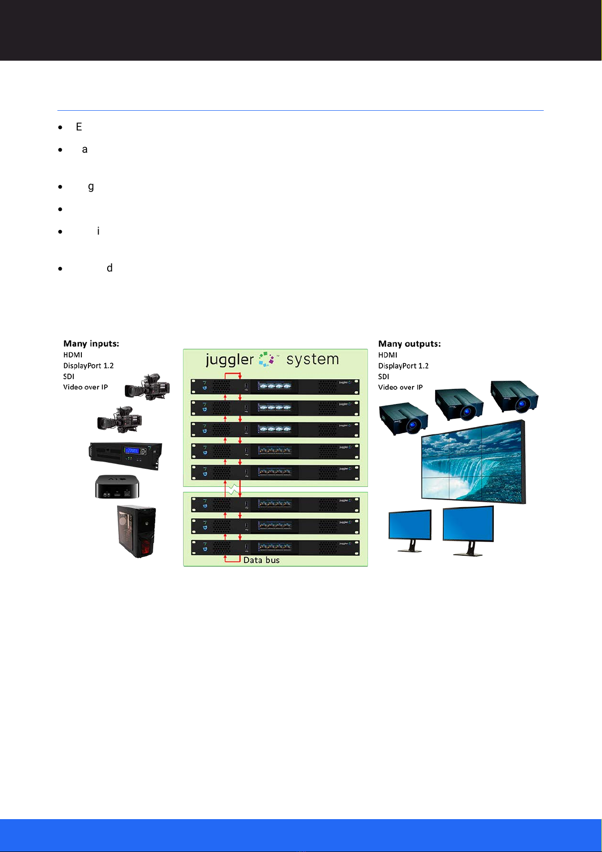
Features and capability of the Juggler pixel processor
·
Modular FPGA-based pixel processor.
·
Configurability: multiple Juggler modules can be daisy-chained via high-speed fibre-optic link, to
add additional input and output capability within a 16K × 4K 10-bit 4:4:4 canvas, or equivalent
bandwidth.

7
M611-1 Operating Juggler 1 Pixel Processor : User Guide © 2022 7thSense
Juggler and Compere
·
Video scaling, video matrixing and picture-in-picture capability, genlocking, framerate conversion.
·
Failover redundant source management with 7thSense IntelligentSource™ (API available).
·
DisplayPort™ 1.2, 12G SDI and HDMI™ 2.0 (optional HDCP™ compliant)
·
DisplayPort output SST to MST conversion.
·
Supports 12-bit 4:4:4 – internal processing at high precision.
·
Colourspace mapping via 3D LUT.
·
External control over IP.
·
User interface: 7thSense Compere software.
·
Warp, blend, and black level output support via MPCDI (2D MPCDI).
·
NDI® 5.0 confidence monitoring.
Ø
Physical Specifications
Ø
Rack Mounting Jugglers
Ø
Care and Maintenance
31
33
34

8
M611-1 Operating Juggler 1 Pixel Processor : User Guide © 2022 7thSense
System Architecture
System Architecture
·
Every Juggler has four video processing channels.
·
Each Juggler unit has a flexible design for provisioning a number of inputs and outputs of various
and mixed types.
·
Jugglers can be daisy-chained by utilising a high capacity data bus.
·
The number and balance of inputs and outputs in a Juggler system is completely scalable.
·
Any input – live capture, streamed or prerecorded – can be processed by any Juggler to any
output and placed anywhere in the overall output space.
·
Redundancy and failover can be built into a Juggler system
As this example shows, the Juggler system maps the whole-site canvas, uniting, processing and
placing all sources with all displays, expanding inputs and outputs as required:

9
M611-1 Operating Juggler 1 Pixel Processor : User Guide © 2022 7thSense
What Juggler Can Do
What Juggler Can Do
Here are two examples of Juggler applications that demonstrate its potential roles.
Example 1: IntelligentSource™ failover
Use cases: Ultra-reliable auto failover, per input, or whole system, seamless source switching
·
A large 16K × 4K canvas
·
IntelligentSource
·
Format conversion
·
Warp and blend
Example 2
·
A large 16K × 4K DisplayPort input canvas
·
IntelligentSource™ failover
·
Picture in picture (PiP)
·
Scaling
·
Warp and blend

10
M611-1 Operating Juggler 1 Pixel Processor : User Guide © 2022 7thSense
What Juggler Can Do

11
M611-1 Operating Juggler 1 Pixel Processor : User Guide © 2022 7thSense
Front Panel: Controls
Power button
Juggler must first be connected to an appropriate power source using the supplied IEC power cord.
The front panel power button will show a dim blue ring indicating this connection. Press and release
the power button to start the unit. The power button will show a bright blue ring and the display panel
will go through a start-up cycle before settling to status information and the Juggler logo.
Reset
Should you need to reset the internal FPGA board only, the power button can be pressed and held for
3 seconds then released when the blue light dims. The blue button light will flash for 2 seconds before
returning to normal status.
USB port
For service use only.
Touch-screen display
The touch screen display is a tabbed swipe and scroll screen: see Front Panel Display .
12

12
M611-1 Operating Juggler 1 Pixel Processor : User Guide © 2022 7thSense
Front Panel: Controls
Front Panel Display
The Juggler front panel touch-sensitive display is driven by a Linux CPU board running a minimised
instance of Compere, which also, as a network client, shares the common Project file for the whole
networked system.
The display presents a menu system that conveys elements of the Compere graphical interface,
allowing direct interaction with, and monitoring of a single Juggler by selecting, and swiping. The
default page that comes up on start-up, and to which other pages revert after 30 seconds, is set in the
properties of the Juggler internal (Linux) processor.
Page 1: Server info
This shows the Juggler name, IP addresses, network mode, project group, project name and
connection status, and subnet. Processor temperatures are also shown.
Page 2: Video Channels Rx, Page 3: Video Channels Tx
This tab provides a direct NDI display of media being processed by the unit, as a row of video
channels 1 to 4. Page 2 is the Rx media, page 3 is Tx media.
Page 4: Set Juggler IP
Swipe to page 4 for editing the static IP address:

14
M611-1 Operating Juggler 1 Pixel Processor : User Guide © 2022 7thSense
Front Panel: Controls
Set Juggler Static IP and Subnet
This can be done from the Juggler front panel touch screen.
·
Touch to select ‘Info’ tab if it is not already showing.
·
Swipe from right to left to move to the IP Editor page:
·
Touch to select an octet (address element) to change; it will show highlighted blue.
·
Use the number pad on the left to enter a value up to 255.
On the number pad:
o. (separator) moves to the next octet
oC (clear) sets the selected octet value to 0
·
Touch ‘Reset’ to undo all changes, or
·
Touch ‘Apply’ and then Confirm the changes:

15
M611-1 Operating Juggler 1 Pixel Processor : User Guide © 2022 7thSense
Rear Panel Connections
The back panel of each Juggler is factory configurable to order. The required number and type of
inputs and outputs for a system of Jugglers is expandable by adding Juggler modules as required.
Working from left to right, these connections are available:
JTAG
Service use only.
UART (serial over USB)
Service use only. Default TCP (alt UDP) connection for Juggler Console to
address the FPGA (field-programmable gate array) processor.
DP CONSOLE
Not used.
OUT and LOOP
Non-user Ethernet ports relating to front panel control, always connected to each
other. (LEDs on OUT are inactive.)
UNIT HDMI Tx and Rx
Used in Juggler modules configured for HDMI, expandable with the I/O Interface
panels.
IN (RJ45)
Network port (LEDs on this port are inactive).
USB 3.0
Not used.
MODULE × 4, numbered 1-4 (options)
4 × SFP modules,
either 12G bidirectional coax (12G-SDI HD-BNC)
or optical fibre (LC) for SDI or to form a 4-lane (‘half’) bus between Juggler
modules
see Connect a Juggler Data Bus
GENLOCK / GPIO – 4 × HD-BNC, numbered 1-4
4 × HD-BNC independent configurable I/O for synchronising; genlock, 3D sync
etc. GPIO and Genlock Juggler Systems
I/O INTERFACE 1 and INTERFACE 2(options)
Choice of 2 × I/O channels of DP 1.2 or HDMI 2.0, or 2 × MPO optical fibre to
form an 8-lane (‘full’) bus between Juggler modules with greater bandwidth than
afforded via SFP transceivers
see Connect a Juggler Data Bus .
SFP Modules
Note the orientation of SDI modules in particular. These are marked with indented arrows, but note
that modules are inserted back to back (lower row inverted):
25
20
25

16
M611-1 Operating Juggler 1 Pixel Processor : User Guide © 2022 7thSense
Rear Panel Connections
The same orientation is true for fibre-optic modules, but these are keyed. If using the 4-lane ‘half’-bus
option to daisy-chain Jugglers, see Connect a Juggler Data Bus : ‘Half bus’.
Important! Only SFP modules approved by 7thSense should be fitted to the Juggler unit, fitting non-
approved SFP modules may cause damage to the Juggler or prevent the unit operating.
Loop cable (every Juggler)
This is a necessary connection, to be kept as short as possible. A 12 cm, black Ethernet cable is
provided for this with every Juggler. It must not be disconnected.
25

17
M611-1 Operating Juggler 1 Pixel Processor : User Guide © 2022 7thSense
Rear Panel Connections
Input and Output Options
In a multi-Juggler system with a data bus, any input of any Juggler can be sent to the bus and taken
off the bus as an input to any other Juggler. These internal interconnections are done in Compere, the
software user interface. For example, this means that an HDMI input can be sent out elsewhere from
the system via SDI.
There are three types of internal connection in a Juggler or a Juggler system:
1. Some Juggler inputs may match its outputs directly, for example providing layers from a media
server to a whole-canvas background, requiring no processing on the way. These can save
bandwidth by using the ‘Bypass’ feature.
2. Other Juggler inputs may occupy an entire video channel, in which case they go directly from
input port to output port.
3. For placing and scaling any Juggler input on the system Canvas, Canvas Windows are matched
onto the input ports, which in turn are passed to Canvas Outputs on output ports.
Ø
For an explanation of terms and parts of the system Canvas, see the Compere 1.0-5 User Guide.
Connection configurations in Juggler modules
Juggler supports connectivity via HDMI™ 2.0, DisplayPort™ 1.2 and 12G SDI. Some typical
configurations of I/O options are shown here.
Media inputs and outputs
HDMI-configured Juggler with a total of 3 × Tx + 3 × Rx HDMI (shown blue) and 2 × Tx + 2 × Rx SDI
(shown red):
HDMI and DisplayPort configured Juggler with 2 × Tx + 2 × Rx HDMI (shown blue) and 2 × Tx + 2 × Rx
DisplayPort (shown green):

18
M611-1 Operating Juggler 1 Pixel Processor : User Guide © 2022 7thSense
Rear Panel Connections
DisplayPort Juggler with 4 × Tx + 4 × Rx DisplayPort (Unit HDMI not enabled):
SDI-enabled Jugglers are equipped with up to four SFP modules (shown red):
Data bus
Each Juggler has four processing channels. By bussing Jugglers together, additional processing
channels can be added to the Juggler system. To bus Juggler modules together, use optical fibre
cables. Full 8-lane bandwidth MPO I/O ports (shown yellow) may be used, or 4-lane SFP modules
(shown magenta). See also Connect a Juggler Data Bus :
These are configured typically alongside 2 × DP or 2 × HDMI in the second interface.
Bus capacity
The bus configuration determines the capacity in terms of resolution and equivalent bandwidth. To
increase bandwidth, lanes 4 and 8 can share their capacity with lanes 1-3 and 5-7. Effectively this
becomes a 6-Lane ‘High Bandwidth’ bus, with lanes 4 and 8 unavailable to separate video channels.
Bits per Pixel determines capacity of your bus for your media requirement.
25

19
M611-1 Operating Juggler 1 Pixel Processor : User Guide © 2022 7thSense
Rear Panel Connections
Bus Mode
Bits Per Pixel
Max Resolution at 60fps,
or equivalent bandwidth
4-Lane Bus
(HD-BNC SFP modules)
8-Lane Bus
(MPO Interface)
30
UHD (3840 × 2160)
4 buses (2 + 2)
8 buses (4 + 4)
24
4800 × 2160
4 buses (2 + 2)
8 buses (4 + 4)
30
High-Bandwidth Mode
4800 × 2160
n/a
6 buses (3 + 3)

20
M611-1 Operating Juggler 1 Pixel Processor : User Guide © 2022 7thSense
Rear Panel Connections
GPIO HD-BNC Ports
Each Juggler back panel has four HD-BNC connnectors. These can be independently designated as
inputs, or outputs that can be assigned to the Juggler’s video channels, in the Juggler properties of
Compere.
All Juggler ports are configured independently in Compere, including GPIO. See Compere User Guide:
GPIO Properties.
These GPIO ports can also be used to support genlocking. For example, on one Juggler in a system,
GPIO:1 can be used to collect the VSync of a media input, pass it out to GPIO:2, collect on GPIO:1 of
the next, out from GPIO:2 and so on to daisy-chain down the line.
Table of contents
Other 7th Sense Recording Equipment manuals
Popular Recording Equipment manuals by other brands

dbx
dbx 266xs user manual

ILITCH ELECTRONICS
ILITCH ELECTRONICS LCNCS User manual and installation instructions

Car Solutions
Car Solutions MB2007-PAS manual

Musikhaus Kirstein
Musikhaus Kirstein Shaman CDL-01 instructions

Focusrite
Focusrite Logic Pro Control surface manual

Global Fire Equipment
Global Fire Equipment GFE-TCP-WEB Configuration manual