A.E.B. med TOP PARKING PLUS 4U User manual

Sistema di parcheggio programmabile con 4 sensori da incasso,
per paraurti in materiale plastico, anteriore o posteriore.
Montaggio dall’interno del paraurti.
Programmable parking system with 4 built-in sensors,
for front or rear plastic bumper.
Assembled from inside the bumper.
ISTRUZIONE DI FUNZIONAMENTO - ITALIANO
USER’S GUIDE - ENGLISH
A U T O M O T I V E S O L U T I O N S
TOP PARKING PLUS 4U
NUMERO DI OMOLOGAZIONE e
APPROVAL NUMBER e
LUGLIO - JULY 2012
1 9 0 1 0 0 06 8
CNT TPP 4U
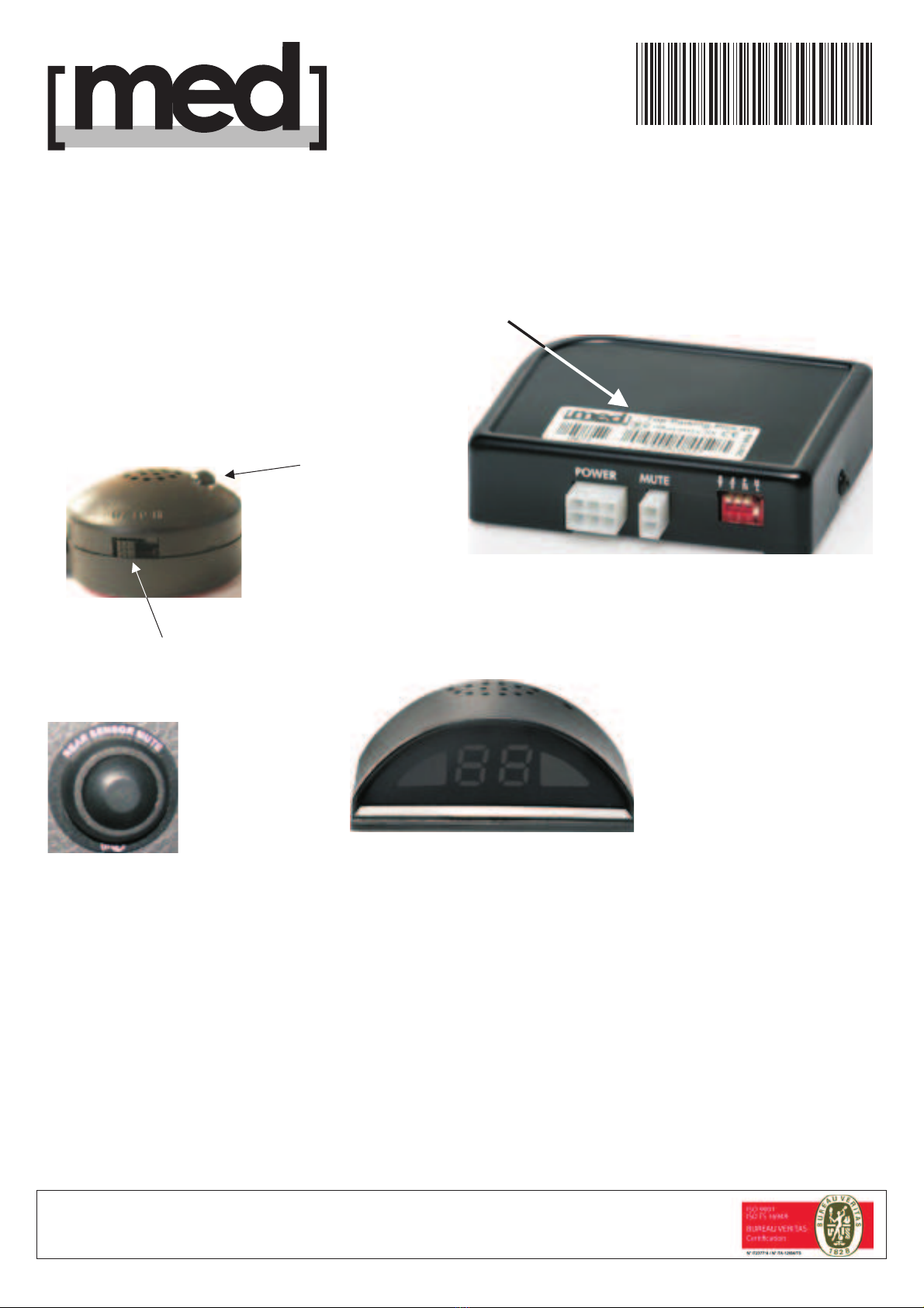
CENTRALINA ELETTRONICA
CENTRAL UNIT
PUL TPP 4U
PULSANTE
BUTTON
MUTE
DISPLAY TP PLUS 4U
DISPLAY CON CICALINO
DISPLAY WITH BUZZER
OPZIONALE - OPTIONAL
LED
INTERRUTTORE
SWITCH
OFF LO HI
CIC TPP 4U
CICALINO
BUZZER
a socio unico / a single member Company - Via dell’Industria, 20
42025 - Corte Tegge - Cavriago (RE) - Italy
med è una divisione di /
A.E.B. S.p.A.
a division of A.E.B. S.p.A.
COMPANY
WITH QUALITY SYSTEM
CERTIFIED BY
BUREAU VERITAS
ISO 9001:2008
www.medautomotive.it

<6 Km/h
1 3
4
R
2
OFF
TEST
1 3
4
R
2
ON OK
BI - BI
1 3
4
R
2
OFF
TEST < 10 Km/h
13
4
R
2
ON OK
BI - BI
< 10 Km/h
ZONA DI RILEVAMENTO DEI SENSORI
ZONES OF DETECTION
- IMPOSTAZIONE STANDARD
- FACTORY SETTINGS
Oppure
OR
2 1 1 2 3
1 = Suono continuo
1 = Continuos tone
2
100
3
210
1
30
Distanza
Distance (cm)
(cm)
ZONA - ZONE
Lettura standard (interruttore 3 OFF)
(switch 3 OFF)Standard reading
2
80
3
150
1
30
Distanza
Distance (cm)
(cm)
ZONA - ZONE
Lettura ridotta (interruttore 3 ON)
(Switch 3 ON)Reduced reading
2
80
1
30
Distanza
Distance (cm)
(cm)
ZONA - ZONE
(Interruttore 3 OFF)
(Switch 3 OFF)
INSTALLAZIONE ANTERIORE
FRONT BUMPER
(interruttore 1 ON)
(Switch 1 ON)
INSTALLAZIONE POSTERIORE
REAR BUMPER
(interruttore 1 OFF)
(Switch 1 OFF)
OFF
ON
1

d
min. 20 cm.
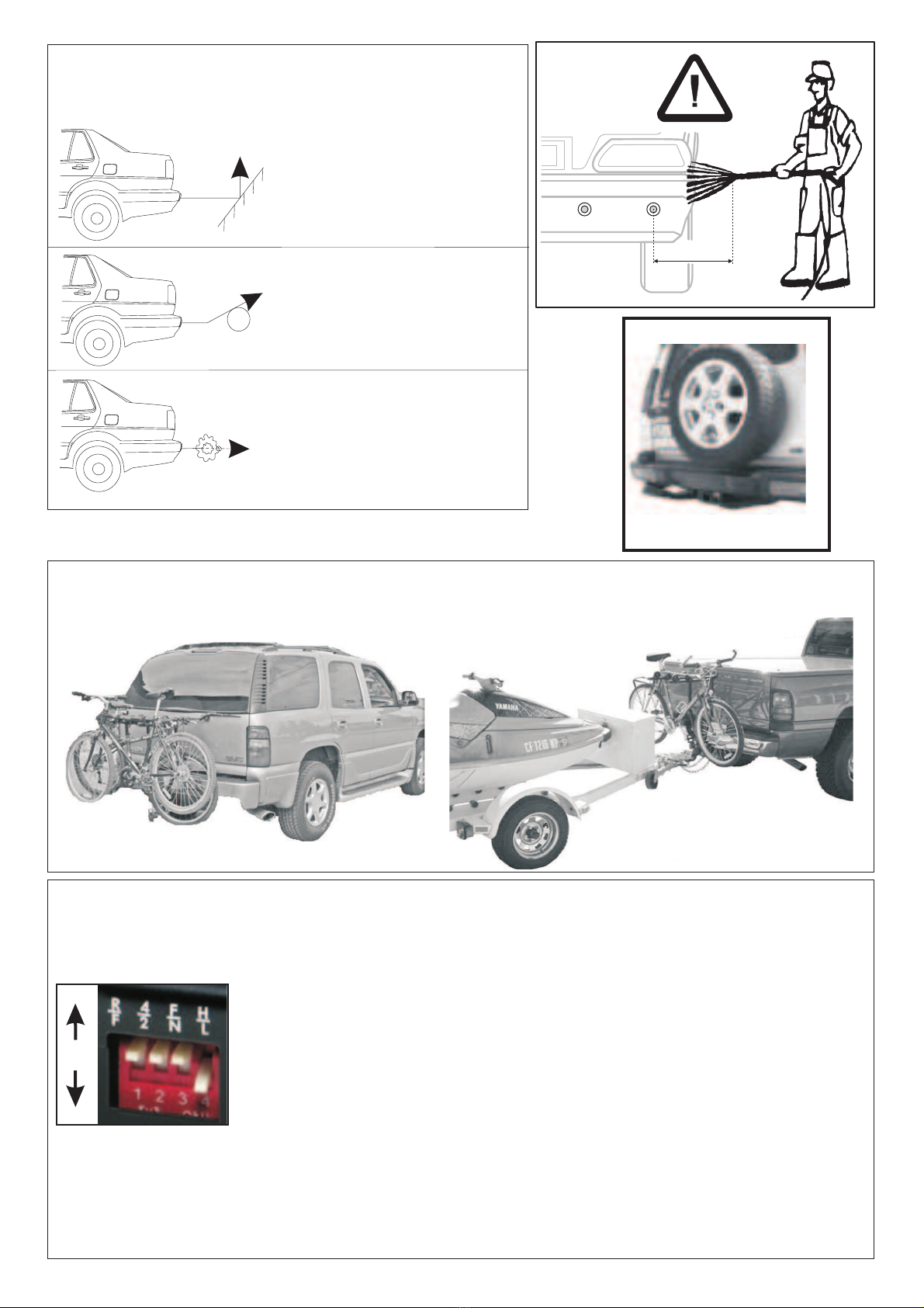
Ostacoli difficili da rilevare
Difficult-to-detect obstacles
Recinzioni basse,
costituite da paletti
di piccolo diametro
Smooth slope
Oggetti rotondi di
piccolo diametro
Smooth round object
Oggetti in materiale assorbente
per gli ultrasuoni,
ad esempio in stoffa.
Object absorbing wave, e.g. cotton
ESCLUDERE COL PULSANTE LA LETTURA DEI SENSORI POSTERIORI:
EXCLUDE READING OF THE REAR SENSORS WITH THE PUSH BUTTON:
OK
2
INTERRUTTORE FUNZIONE
= Installazione su paraurti posteriore - F
= Installazione su paraurti anteriore - R
= Installazione con 4 sensori - 4 sensor
= Installazione con 2 sensori - 2 sensor
= Lettura standard -
= Lettura ridotta -
= Sensibilità alta - High sensitivity
= Sensibilità bassa - Low sensitivity
1
2
3
4
¯
¯
¯
¯
ront bumper
ear bumper
Standard reading
Reduced reading

INTRODUZIONE
FUNZIONAMENTO
TOP PARKING PLUS 4U
cicalino OFF LO HI
30
DISPLAY TP PLUS 4U
DISPLAY TP PLUS 4U
TOP PARKING PLUS 4U è quindi un importante aiuto nella fase di manovra, ma
è sempre il conducente che deve valutare gli ostacoli, tenendo uno stile di
guida attento e prudente, per non arrecare danni a cose o persone.
AVVERTENZE:
Le manovre devono sempre essere effettuate con la massima cautela ed attenzione.
30 cm
Lavandoli con getti d'acqua in pressione o a getto di vapore, mantenersi ad almeno
20 centimetri di distanza
può essere installato anteriormente o posteriormente al veicolo, su
tutti i paraurti in materiale plastico, a partire dall’altezza minima di 45 centimetri (con paraurti
verticale).
Dispone di 4 sensori con filtro antidisturbo integrato, per proteggere uniformemente il veicolo,
ma se il mezzo ha dimensioni contenute, è possibile installarlo con solo 2 sensori.
Il (con interruttore a 3 posizioni: spento - basso - alto ) segnala con BIP
sempre più rapidi l'avvicinarsi agli ostacoli fino alla distanza minima di circa cm (suono
continuo), come il LED a 3 colori integrato, con: verde - giallo - rosso lampeggiante.
Consigliamo l'abbinamento del con cicalino integrato (opzionale) per
visualizzare graficamente sia la distanza minima (indicazione numerica) del sensore più vicino
all’ostacolo, che la modalità di avvicinamento: segmenti a led si accendono in modo
indipendente: prima verde, poi giallo, quindi rossi, all’avvicinarsi dell’ostacolo.
Il consente di effettuare numerose impostazioni, riportate a pag. 6.
- E' possibile incappare in oggetti che potrebbero non essere rilevati correttamente, come
ad esempio: ostacoli molto bassi, sottili, appuntiti o con ridotta riflessione.
- Fermare il veicolo appena il cicalino suona fisso, perché indica la presenza di un ostacolo a
circa dai sensori.
- Mantenere i sensori puliti da neve, fango o sporcizia, per evitare malfunzionamenti.
Pulirli con acqua ed un panno morbido.
Non utilizzare panni asciutti o ruvidi, per evitare di graffiare o danneggiare i sensori.
-
.
Possono verificarsi false segnalazioni:
- In caso di forte vento o piogge intense.
- In presenza di superfici fortemente irregolari (neve, fango, strade sterrate) o quarzite
(materiale usato per pavimentazioni).
- In presenza di ostacoli con superfici poco riflettente.
:
Accendendo la chiave quadro, il led verde del cicalino si accende: i sensori sono attivi.
- BIP e LED giallo indicano l’avvicinarsi a meno di 80 centimetri degli ostacoli.
- BIP continuo e LED rosso lampeggiante se l’ostacolo è a meno di 30 centimetri.
- La segnalazione si interrompe se l’ostacolo rimane fermo rispetto al veicolo per più di 4
secondi.
Si riattiva appena l’ostacolo o il veicolo si muovono.
Il pulsante in dotazione permette di disattivare / riattivare il sistema (vedereAUTODIAGNOSI).
L’esclusione resta valida sino alla prossima accensione della chiave quadro.
SENSORI ANTERIORI
ITALIANO
3

SENSORI POSTERIORI
VEICOLI CON GANCIO DI TRAINO O RUOTA DI SCORTA SPORGENTE
20 centimetri
:
L’installazione posteriore dei sensori consente, in fase di montaggio, di scegliere la distanza di
inizio rilevamento degli ostacoli: 210 centimetri (lettura standard) o 150 cm (lettura ridotta).
Innestando la retromarcia, un BIP del cicalino ed il LED verde acceso indicano l’entrata in
funzione del sistema.
- BIP lento e LED verde lampeggiante indicano l’avvicinarsi nella zona di rilevamento di un
ostacolo: a meno di 210 cm (lettura standard) o 150 cm (lettura ridotta).
- BIP sempre più veloci e LED giallo avvicinandosi ulteriormente all’ostacolo.
- BIP continuo e LED rosso lampeggiante se l’ostacolo è a meno di 30 centimetri.
- La segnalazione si interrompe se l’ostacolo rimane fermo rispetto al veicolo per più di 3
secondi. Si riattiva appena l’ostacolo o il veicolo si muovono.
Il pulsante in dotazione permette di disattivare il sistema, ad esempio se si aggancia un
rimorchio. L’esclusione resta valida sino alla prossima accensione della chiave quadro.
può essere installato su questi veicoli, disponendo della capacità di
memorizzarne gli ingombri effettuandone l’autoapprendimento della loro sporgenza:
1) Posizionare il veicolo in una zona senza ostacoli posteriori, lasciando il motore acceso.
2) Innestare la retromarcia per 2 secondi, toglierla per altri 2 secondi.
3) Ripetere 3 volte il punto 2.
4) Conferma: il LED passa da rosso a giallo, poi verde senza emettere suoni, poi un BIP
prolungato conferma il buon esito dell’operazione.
5) Spegnere il motore.
- L’impostazione resta valida sino alla sua ripetizione in modo completo.
- Gli accessori devono essere fissati saldamente al veicolo (ruota di scorta, gancio di traino).
- Ignora oggetti che fuoriescono dalla linea del paraurti per meno di 20 centimetri, purchè
non coprano direttamente i sensori.
(30 centimetri di distanza minima + 20 centimetri per l’eventuale sporgenza: ruota di
scorta, gancio traino, etc.
- Ostacoli nascosti dagli oggetti fissati al veicolo non possono essere rilevati.
A.E.B. S.p.A. declina ogni responsabilità e sospende la GARANZIA in caso di utilizzo improprio
del prodotto o di parte di esso, di manomissione o di abbinamento a dispositivi non previsti.
A.E.B. S.p.A. si riserva la facoltà di apportare in ogni momento migliorie al prodotto.
- Posizionare la centralina in zona protetta dall'infiltrazione di liquidi, coi cavi che arrivano
dal basso per evitare che convoglino acqua; non posizionare la centrale, i sensori o i
cablaggi in prossimità di fonti di calore intenso, quali motore o impianto di scarico.
- L'installazione deve essere eseguita da personale qualificato.
- A.E.B. S.p.A. non può essere ritenuta responsabile in caso di danni al veicolo o alle
persone dovuti a mancate o ritardate segnalazioni di ostacoli; è l’autista che deve tenere
un comportamento di marcia adeguato alle condizioni, prestando la massima attenzione
anche durante le operazioni di manovra; TOP PARKING PLUS è uno strumento di
assistenza alla manovra.
La garanzia tecnica ha durata di 24 mesi a partire dalla data di installazione, franco fabbrica, per
le parti ritenute difettose ad insindacabile giudizio A.E.B. S.p.A. Sono escluse da tale forma di
copertura spese di manodopera esterna ed ogni altro onere a qualsiasi titolo.
TOP PARKING PLUS 4U
ATTENZIONE:
In questo caso tutte le distanze rilevate risulteranno maggiorate di .
Il buzzer ora suonerà fisso alla distanza di circa 50 centimetri tra l’oggetto rilevato ed i
sensori
CONDIZIONI DI GARANZIA
4

AUTODIAGNOSI
MANUTENZIONE
OMOLOGAZIONI
CARATTERISTICHE TECNICHE
SENSORI ANTERIORI
SENSORI POSTERIORI
:All’accensione della chiave quadro, il sistema effettua una verifica.
L’esito è rappresentato nella seguente tabella:
:All’inserimento della retromarcia, il sistema effettua una verifica.
L’esito è rappresentato nella seguente tabella:
Il sistema non richiede nessuna manutenzione. I sensori devono essere mantenuti puliti.
è omologato secondo la riguardante
la compatibilità elettromagnetica (interferenze e disturbi) col n.
Tensione di alimentazione: /
Frequenza ultrasuoni:
Assorbimento di corrente: (a motore spento)
Massimo: (a motore acceso, con sistema attivo)
Campo di temperatura: da a
Posizionamento: (anteriore) / (posteriore)
Protezione: (IEC 529 1989) - DIN 40050 - EN 60529
ATTENZIONE:
- Se vengono segnalate anomalie, ripristinare il sistema al più presto.
- Mantenere puliti i sensori.
TOP PARKING PLUS 4U Direttiva Europea 2006/28/CE
e13 03 12490
9 16 Vdc
58 kHz
0 mA
20 mA
-20 °C + 80 °C
all’interno dell’abitacolo del baule
IP 40
Suoni cicalino LED Indicazione
Nessun suono verde Funzionamento anteriore corretto
2 BIP rosso 1 sensore danneggiato / guasto / staccato
3 BIP rosso 2 o 3 sensori danneggiati / guasti / staccati
4 BIP rosso Nessun sensore funzionante / collegato
1 BIP breve rosso Pulsante premuto - sensori anteriori
2 BIP brevi rosso Pulsante premuto - sensori anteriori
attivi
disattivati
Suoni cicalino LED Indicazione
1 BIP lungo giallo Sistema programmato
1 BIP verde Funzionamento posteriore corretto
2 BIP rosso 1 sensore danneggiato / guasto / staccato
3 BIP rosso 2 o 3 sensori danneggiati / guasti / staccati
4 BIP rosso Nessun sensore funzionante / collegato
5

DISPLAY TP PLUS 4U OPZIONALE
Visualizza graficamente sia la distanza minima del sensore più vicino all’ostacolo, che la
modalità di avvicinamento: segmenti a led si accendono in modo indipendente: prima verde, poi
giallo, quindi rosso, all’avvicinarsi dell’ostacolo.
Il display a 2 cifre integrato fornisce indicazioni sulla modalità di funzionamento, sulla distanza
dall’ostacolo, nonché per le programmazioni in corso.
Ad ogni attivazione del sistema si effettua l’autodiagnosi, pertanto il display indica:
= Diagnosi ok: sistema regolarmente funzionante.
= Diagnosi ok con “controllo ruota di scorta”: sistema regolarmente funzionante.
= Guasto: sensore / sensori guasti, danneggiati, scollegati.
= Controllo ruota di scorta in corso.
Sono disponibili 2 diversi livelli di funzionamento:
1) Per visualizzare le impostazioni precedentemente impostate.
2) Per cambiare le impostazioni.
:
A) Individuare il piccolo foro di accesso al pulsante posto nella parte superiore del display
(sulla parte arrotondata, a fianco dei fori per il cicalino).
B) Con una punta sottile (ad esempio con una graffetta fermacarte), pigiare delicatamente il
pulsante. Ogni breve pressione permette di avanzare di un passo (es. F1, F2, ... F7).
C) Per visualizzare come è impostata quella funzione (es. F1), appena la si visualizza (F1),
mantenere premuto il pulsante per 2 secondi.
Ora si visualizza il valore impostato (es. 14 = volume molto alto).
D) Ogni ulteriore breve pressione sul pulsante permette di variarne il valore. Il display mostra
ciclicamente tutti i valori selezionabili per quella funzione (es. 14, 10, 11, 12, 13, 14, 10, ...).
E) Raggiunto il valore desiderato, mantenere premuto il pulsante per 4 secondi.
F) Ripetere dal punto B) la procedura per ogni valore che si vuole visualizzare / modificare.
: Per effettuare la procedura, il sistema deve essere in funzione (display acceso).
Dopo 4 secondi senza pressioni sul pulsante, il sistema riprende il normale funzionamento.
Volume 10 ~ 14 11 = basso 14 = alto 10 = muto
Tono BIP 21 ~ 28 21 = basso 28 = alto
Luminosità 31 ~ 34 31 = bassa 34 = alta nota 1-
Inversione immagine 41 ~ 42 41 = normale 42 = invertita
Distanza (in piedi o metri) 51 ~ 52 51 = piedi 52 = metri nota 2-
LED fisso /
lampeggiante (zone 2 e 3) 61 ~ 62 61 = fisso 62 = lampeggiante nota 3-
Segnalazione sotto 71 ~ 71 71 = solo LED 72 = LED + BIP nota 4-
i 30 centimetri
:
La luminosità del display si dimezza se viene impiegato coi sensori installati anteriormente.
La distanza evidenziata sul display è arrotondata ai 10 centimetri superiori.
Impostandolo lampeggiante, le indicazioni delle zone 2 e 3 verranno mostrate lampeggianti.
Attivabile solo coi sensori installati anteriormente.
dP
dL
dF
LS
PROCEDURA
ATTENZIONE
F1
F2
F3
F4
F5
F6
F7
Note
1-
2-
3-
4-
PROGRAMMAZIONI DISPLAY
(posteriore)
6

INTROD
can be installed at the front or rear of the vehicle on all plastic
bumpers starting from a minimum height of 40 centimetres (in the case of vertical bumpers).
It is equipped with 4 sensors with built-in anti-interference filter to protect the vehicle uniformly
but if the vehicle is small it can be installed with just 2 sensors
The (with 3-position switch: - - ) signals with an increasingly fast BEEP that
the obstacle is getting closer, up to a minimum distance of about (when it becomes
continuous), like the built-in 3-colour LED, with: green - yellow flashing red.
We advise you to combine the with built-in buzzer (optional) to
graphically view both the minimum distance (numerical indication) of the senso
alling stops if the obstacle does not move in relation to the vehicle for more than 4
seconds
It starts again as soon as the obstacle or vehicle moves
The push button supplied allows the system to be deactivated/reactivated (see SELF
DIAGNOSIS).
Exclusion is valid up until the next time the panel key is turned on.
buzzer OFF LO HI
30 cm
TP PLUS 4U DISPLAY
UCTION
FUNCTIONING
TOP PARKING PLUS 4U
TOP PARKING PLUS 4U is therefore an important aid in maneuvering, but it is
always the driver who has to assess the obstacless, maintaining a careful
and prudent driving style, so as not to cause damage to property or persons.
WARNING:
The vehicle maneuvers should always be made with great care and attention.
30 cm
Wash them with jets of pressurized water or jets of steam, maintaining at least 20
cm distance from the sensors
r nearest the
obstacle and the approaching mode: LED segments light up independently: first green, then
yellow and red as you get closer to the obstacle.
The TP PLUS 4U DISPLAY allows a great number of settings, given on page 10.
- Objects can be encountered that may not be detected correctly, for example: obstacles
that are very low, thin, pointed or with reduced reflection.
- Stop the vehicle as soon as the buzzer sounds continuously, because it indicates the
presence of an obstacle at about from the sensors.
- Keep the sensors clean of snow, mud or dirt, to prevent malfunctioning. Clean them with water
and a soft cloth. Do not use dry or rough cloths to avoid scratching or damaging the sensors.
-
; under this condition, sensors can temporarily lose some of
their sensitivity, which then is restored when the water has completely evaporated.
False signals can be given:
- In cases of strong winds or intense rain.
- In the presence of highly irregular surfaces (snow, mud, dirt roads) or quartzite (material
used for paving).
- In the presence of obstacles with poorly reflecting surfaces.
When the panel key is turned on the green buzzer LED lights up: the sensors are active.
- BEEPS and the yellow LED mean you are less than 80 centimetres from the obstacles.
- A continuous BEEP and a flashing red LED mean the obstacle is less than 30 centimetres
away.
- Sign
FRONT SENSORS:
.
.
.
ENGLISHENGLISH
7

REAR SENSORS:
When installing the rear sensors you can choose the distance at which they start detecting
obstacles: 210 centimetres (standard reading) or 150 cm (reduced reading).
When engaging the reverse gear, a BEEP from the buzzer and the green LED on mean the
system has started working.
-
Increasingly quick BEEPS and a yellow LED mean the vehicle is getting even nearer the
obstacle
- Signalling stops if the obstacle does not move in relation to the vehicle for more than 3
seconds. It starts again as soon as the obstacle or vehicle moves.
The push button s
TOP PARKING PLUS 4U can be installed on these vehicles as it has the function of memorising
the dimensions by self-learning their projecting distance:
1) Position the vehicle where there are no obstacles at the back and leave the engine running.
2) Engage the reverse gear for 2 seconds, disengage it for other 2 seconds.
3) Repeat step 2 three times.
4) Confirm: the LED changes from red to yellow and then green without making any noise, then
a long BEEP confirms that everything has gone well.
5) Turn the engine off.
- The setting is valid until it is repeated again completely.
- The accessories must be firmly secured to the vehicle (spare wheel, tow hook).
- It ignores objects that go less than 15 to 18 centimetres beyond the line of the bumper
provided they do not cover the sensors directly.
(30 centimetres minimum distance +20
centimetres for any protrusions: spare wheel, tow hook, etc.).
- Obstacles hidd
A.E.B. S.p.A. assumes no liability and suspends the guarantee in case of improper use of the
product or part thereof, of mishandling or of combination with devices not planned for A.E.B.
S.p.A. reserves the right to make improvements in the product at any time.
- Positiom the electrical control unit in a place protected from seepage of liquids, with wires
exiting from the bottom to prevent conveyance of water; do not place the control unit, sensors
or wires near sources of intense heat, such as the motor or exhaust system.
- The installation must be executed with qualified personnel.
- A.E.B. S.p.A. cannot be held responsible for any damage to vehicles or persons due to
failure or delayed signalling of obstacles; it is the driver who must maintain driving
comportment adequate to the conditions, paying maximum attention during maneuvering
activity.
TOP PARKING PLUS 4U is an instrument of assistance to maneuvering.
The technical guarantee has a duration of 24 months from the date of installation, ex factory, for
the parts deemed faulty at the sole discretion of A.E.B. S.p.A. external labor costs and every
other expense of any kind are excluded from this form of coverage.
A slow BEEP and a green flashing LED mean you are approaching an area where an
obstacle is detected: at less than 210 centimetres (standard reading) or 150 cm (reduced
reading).
-
.
- Acontinuous BEEP and a flashing red LED mean the obstacle is less than 30 centimetres away.
VEHICLES WITH TOW HOOK OR SPARE WHEEL PROTRUDING FROM THE VEHICLE
CAUTION:
In this case, all the distances detected will be increased 20 centimetres.
The buzzer will now beep continuously at a distance of approximately 50 centimetres
between the object detected and the sensors
CONDITIONS OF GARANTEE
upplied is used to deactivate the system if, for example, you hook on to a
trailer. Exclusion is valid up until the next time the panel key is turned on
en by the objects fixed on the vehicle cannot be detected
.
.
8

AUTO-DIAGNOSIS
MAINTENANCE
APPROVAL
TECHNICAL CHARACTERISTICS
FRONT SENSORS
REAR SENSORS
:
:
When the panel key is turned on the system runs a check.
The outcome is shown in the following table:
When the reverse gear is engaged the system runs a check.
The outcome is shown in the following table:
If anomalies are indicated reset the system as soon as possible
Keep the sensors clean
The system does not require any maintenance.
The sensors must be kept clean.
is homologated in compliance with the
concerning the electromagnetic compatibility (interferences and noises) under the
following approval n.
Voltage SUPPLY: /
Ultrasonic frequency:
Current absorption: (engine not running)
Maximum: 20 (with engine running, with system ON)
Temperature range: from to
Location: (front) - (rear)
Protection: (IEC 529 1989) - DIN 40050 - EN 60529
WARNING:
- .
- .
TOP PARKING PLUS 4U European Directive
2006/28/EC
e13 03 12490
9 16 Vdc
58 kHz
0 mA
mA
- 25 °C + 80 °C
under the dashboard in the boot
IP 40
9
Buzzer beeping Indication
No beeps Working correctly at the front
1 sensor damaged / failed / come off
2 or 3 sensors damaged / failed / come off
None of the sensors working / connected
1 short BEEP Push button pressed - front sensors
2 short BEEPs Push button pressed - front sensors
active
deactivated
LED
green
2 BIP red
3 BIP red
4 BIP red
red
red
Buzzer beeping Indication
1 long BEEP System programmed
Working correctly at the rear
1 sensor damaged / failed / come off
2 or 3 sensors damaged / failed / come off
None of the sensors working / connected
LED
yellow
1 BIP green
2 BIP red
3 BIP red
4 BIP red

DISPLAY TP PLUS 4U - OPTIONAL
y view the minimum distance of the sensor nearest the obstacle and the approaching
mode: LED segments light up independently: first green, then yellow and red as you get closer
to the obstacle.
The integrated 2-digit display provides information about the mode, distance from the obstacle
as well as the ongoing programming.
Each time the system is activated it carries out a self-diagnosis, therefore the display indicates
that:
= Diagnostic Passed: system is functioning correctly.
= Diagnostic Learned: system is functioning correctly, with learned.
= Diagnostic Faulted: with sensor disconnected / damaged.
= Learning Scanning: on the learning procedure.
2 different operating modes are available:
1) To view the previously set settings.
2) To change the settings.
A) Find the tiny hole to reach the push button which is at the top of the display (on the rounded
part, by the side of the buzzer holes).
B) Press the push button delicately with a small point (e.g. paper clip). You move one step
each time it is pressed (e.g. F1, F2, ... F7).
C) To edit the chosen function press and hold the button down for 2 seconds - the display will
change from function (es. F1), to the current level (es. 14 = highest volume).
D) Each short press on the tact switch will cycle through the available levels in that function
(es. 14, 10, 11, 12, 13, 14, 10, ...).
E) Once the required level is set, leave the unit for 4 seconds to return to operational status.
F) Repeat the steps to configure other functions.
That if there is no adjustment made for 4 seconds, the system will automatically return to
operational status.
Volume setting 10 ~ 14 11 = lowest 14 = highest 10 = mute
Ring Tone setting 21 ~ 28 21 = lowest 28 = highest
Brightness setting 31 ~ 34 31 = light 34 = bright note 1 -
Front display or rear 41 ~ 42 41 = normal 42 = reversed (rear)
Distance (feet / meter) 51 ~ 52 51 = feet 52 = meter note 2 -
Alarm LED active by solid
/ flash (zone 2 & 3) 61 ~ 62 61 = solid 62 = flash note 3 -
71 ~ 71 71 = LED only 72 = LED + audible alert note 4 -
30 centimetres
:
The brightness of the LEDs is 50 % lower when the system is used fot front detection.
The display distance will be shown in 10 cm (or 4 feet) increments.
When set to flash mode, the LEDs will both display the distance to the nearest obstacle.
This function is only available in front mode.
dP
dL
dF
LS
PROCEDURE:
WARNING:
F1
F2
F3
F4
F5
F6
F7
Note
1 -
2 -
3 -
4 -
DISPLAY SETTING ADJUSTMENT
Graphicall
To carry out the procedure, the system must be operating (display turned on).
Signalling under
10

Cod. 190.100.068 - Rev. 02 del 29.08.2012 printed in italy
Il sottoscritto, ________________________________________________________Thendersigned:
Installatore CERTIFICA di aver eseguito PERSONALMENTE il montaggio del DISPOSITIVO descritto
qui di seguito, conformemente alle istruzioni del fabbricante.
Installed CERTIFIES that the fitting of the DEVICE described below was carried out by him
PERSONALLY, in accordance with the instructions of the manufacturer.
Descrizione del VEICOLO - Description of the VEHICLE:
MARCA, _____________________MODELLO, ___________________TRADEMARK: TYPE:______
NUMERO di TARGA, PLATE _________________________________________NUMBER:_
Descrizione del DISPOSITIVO - Description of the DEVICE:
Applicare nei riquadri le etichette adesive fornite in confezione con i dati indicati e completare il modulo.
___________________________________ Il, On: ____________________
Apply the supplied labels with the relevant data and complete the form.
Installato a, Installed at:
Indirizzo completo dell'installatore,
___________________________________
FIRMADELL'INSTALLATORE, SIGNATURE:
___________________________________
Full address of installer:
___________________________________
___________________________________
AVVERTENZE GENERALI PER L'UTENTE:
!
!
L'INSTALLAZIONE deve essere eseguita da PERSONALE QUALIFICATO, secondo le istruzioni
specifiche.
L'INSTALLATORE DEVE compilare e firmare il presente CERTIFICATO DI GARANZIA.
eclina ogni responsabilità e sospende la GARANZIA in caso di utilizzo improprio del
prodotto o di parte di esso, di manomissione o di abbinamento a dispositivi non previsti.
A.E.B. S.p.A. d
GENERAL WARNINGS FOR THE USER:
!INSTALLATION must be conducted by QUALIFIED PERSONNEL and according to the
instructions.
A.E.B. S.p.A. declines all responsibility and withdraws the GUARANTEE / WARRANTY in cases of:
the improper use of the product or part there of, tampering with the product, its combination with
devices for which it was not specifically designed.
!THE INSTALLER HAS TO sign and fill this CERTIFICATE OF GUARANTEE.
Modello, Type
Matricola, Registration
TOP PARKING PLUS 4U
CERTIFICATO DI GARANZIA - WARRANTY CERTIFICATE
TIMBRO, STAMP
SI PREGA DI SCRIVERE IN STAMPATELLO
PLEASE WRITE IN BLOCK LETTERS
a socio unico / a single member Company - Via dell’Industria, 20
42025 - Corte Tegge - Cavriago (RE) - Italy
med è una divisione di /
A.E.B. S.p.A.
a division of A.E.B. S.p.A.
COMPANY
WITH QUALITY SYSTEM
CERTIFIED BY
BUREAU VERITAS
ISO 9001:2008
www.medautomotive.it
Tutti i diritti riservati. © 2012AEB S.p.A. a socio unico
Con riserva di modifiche e di indicazioni errate.
All rights reserved. © 2012 a single member
Company. Subject to changes and incorrect information.
AEB S.p.A.

ISTRUZIONI DI MONTAGGIO
FITTING GUIDE
Sistema di parcheggio con 4 sensori da incasso per paraurti anteriore o posteriore.
Parking system with 4 sensors to embed in front or rear bumper.
A U T O M O T I V E S O L U T I O N S
TOP PARKING PLUS 4U
1 9 0 1 0 0 0 6 9
PUL TPP 4U
PULSANTE
BUTTON
MUTE
CIC TPP 4U
CICALINO
BUZZER
CNT TPP 4U
CENTRALINA PROGRAMMABILE
CONTROL UNIT
DISPLAY TP PLUS 4U
DISPLAY CON CICALINO
DISPLAY WITH BUZZER
OPZIONALE - OPTIONAL
SEN TPP 4U
SENSORE
SENSOR
CHP 205
OPZIONALE
OPTIONAL
a socio unico / a single member Company - Via dell’Industria, 20
42025 - Corte Tegge - Cavriago (RE) - Italy
med è una divisione di /
A.E.B. S.p.A.
a division of A.E.B. S.p.A.
COMPANY
WITH QUALITY SYSTEM
CERTIFIED BY
BUREAU VERITAS
ISO 9001:2008
www.medautomotive.it
OTTOBRE - OCTOBER 2014
LED
INTERRUTTORE
SWITCH
OFF LO HI

CONTENUTO DELLA CONFEZIONE - PACKAGING CONTENT
1
TOP PARKING PLUS 4U
DISPLAY TP PLUS 4U
CHP 205
1
4
4
1 LS
1 LC
1 RC
1 RS
1
1
1
1
1
1
1
1
1
8
8
1
1
1
1
1
1
2
2
x = Centralina programmabile - Control Unit
x = Sensori cablati -
x = Cavi prolunga sensori - Sensor extension cable:
x = Sinistro, Laterale - Left
x = Sinistro, Centrale - Left Central
x = Destro, Centrale - Right Central
x = Destro, Laterale - Right
x = Cavo di alimentazione sistema - Cavo di alimentazione sistema
x = Cicalino - Buzzer
x = Cavo di prolunga per cicalino - Buzzer extension cable
x = Pulsante cablato ON / OFF (mute) -
x = Sacchetto accessori, contenente: -Accessories package, containing
x Velcro adesivo per fissaggio centralina -
x Primer
x Salviettina detergente -
x FRONT / REAR - Mostrina per pulsante ON / OFF -
x Biadesivi di fissaggio sensori - Bi-adhesive stickers
x Fascette fissaggio cavi - Cable fixing band
x Vite con rondella fissaggio cicalino -
- OPZIONALE - OPTIONAL
x Display con slitta di fissaggio - Display with mounting slide
x Cavo prolunga display - Display cable extension
x Sacchetto accessori display, contenente: - Display accessories package, containing:
x Biadesivo di fissaggio display - Bi-adhesive display
x Salviettina detergente - Cleansing towelette
x Fascette fissaggio cavi - Cable fixing band
x Viti fissaggio slitta display - Display mounting slide screws
- OPZIONALE - OPTIONAL
Attrezzo manuale consigliato per effettuare il foro nel paraurti
in materiale plastico.
Hand tool recommended for making the hole in the plastic bumper.
CNT TPP 4U
SEN TPP 4U
CAV SEN TPP 4U
CAV TPP 4U
CIC TPP 4U
CAV CIC TPP 4U
PUL TPP 4U
SAC TPP 4U
Sensors wired
ON / OFF (mute) button wired
Adhesive Velcro for mounting control box
Cleansing towelette
Plate for ON / OFF button
Buzzer mounting screws with washer
:

2
OFF
ON
BIANCO
WHITE
NERO - NERO/BIANCO
BLACK - BLACK/WHITE
ARANCIONE - ORANGE
250V - 1A
FUSIBILE - FUSE
GND
DISPLAY TP PLUS 4U
DISPLAY CON CICALINO -
DISPLAY WITH BUZZER -
OPZIONALE
OPTIONAL
NERO
BLACK
ROSSO - RED
Cavo prolunga display
Uso facoltativo
Display cable extension
Optional use
12 VCC
+15
250V - 1A
FUSIBILE - FUSE
+12VCC
GND
+
1 3
4
R
2ON
GIALLO
YELLOW
BIANCO
WHITE
CIC TPP 4U
NERO
BLACK
NERO
BLACK
SENSORI SULLA
PARTE ANTERIORE
SENSORS FRONT
BUMPER
SENSORI SULLA
PARTE POSTERIORE
SENSORS REAR
BUMPER
LUCE
RETROMARCIA
REVERSING
LIGHT
DA ISOLARE
TO INSULATE
FRONT
REAR
PUL TPP 4U
NERO
NERO/BIANCO
BLACK
BLACK/WHITE

R
LS LC RC RS
LS LC RC RS
LC RS
ANTERIORE
FRONT
POSTERIORE
REAR
NO
OK
NO
OK
m
Biiiiiiiiiii
Bi - Bi - Bi - Bi
0~0.3 m
0.3~0.8 m
- INSTALLAZIONE
CON CONTROLLO
LATERALE
MAGGIORE
- INSTALLATION
WITH INCREASED
SIDE CONTROL/
DETECTION
BUZZER
CIC TPP 4U
L
AB 000 CDAB 000 CD
LS
L : 8 = 1 / 8
1/8 x 2 = 2/8
= == =
Bi - - - - - - - Bi
0.8~1.5 m
1/8L
2/8L 2/8L2/8L
1/8L
L
AB 000 CDAB 000 CD
- INSTALLAZIONE
CON CONTROLLO
LATERALE RIDOTTO
- INSTALLATION
WITH REDUCED
SIDE CONTROL/
DETECTION
BUZZER
CIC TPP 4U
0~0.3 m
0.3~0.8 m
0.8~1.5 m
Biiiiiiiiiii
Bi - Bi - Bi - Bi
= =
L - 12 cm = L1
L : 4 = 1 / 4 L
1 1
Bi - - - - - - - Bi
1/4L11/4L11/4L1
0° ÷ +5°
45 ÷ 80 cm
LC RC RS
LC RC RS
LS
OK
4X
2X
NO
OK
RC
LS
LC RS
RC
LS
LC RS
RC
LS
LC RS
RC
LS
LC RC
LC RC
LC RC
LC RC
NO
NO
NO
NONO
= 50 Mµ
SPESSORE VERNICE
VARNISH THICKNESS
GAUGE
3

4
MONTAGGIO SENSORI - MOUNTING SENSORS
PRIMER
3M 4298UV
20
- ATTENZIONE USARE
UTENSILI IDONEI
- PUNTA
- TWIST DRILL
Ø 20 mm
- WARNING!
USE SUITABLE TOOLS
8
- INSTALLAZIONE CONSIGLIATA
CON CHP 205
CHP 205
OPZIONALE
- RECOMMENDED INSTALLATION
WITH OPTIONAL
- PUNTA
- TWIST
DRILL
Ø 8 mm
A
C
B
UP
RETRO
SENSORE
REAR
SENSOR

5
DISPLAY TP PLUS 4U
OPZIONALE - OPTIONAL
Biadesivo di fissaggio
Bi-adhesive stickers Vite
Screw
CNT TPP 4U
Vite
Screw
Oppure
Or
Biadesivo di fissaggio
Bi-adhesive stickers
PREMERE
PRESS ON
PREMERE
PRESS ON
PREMERE e SFILARE
PRESS ON and SLIP OFF
INTERRUTTORE FUNZIONE
= Installazione su paraurti posteriore - F
= Installazione su paraurti anteriore - R
= Installazione con 4 sensori - 4 sensor
= Installazione con 2 sensori - 2 sensor
= Lettura standard -
= Lettura ridotta -
= Sensibilità alta - High sensitivity
= Sensibilità bassa - Low sensitivity
1
2
3
4
¯
¯
¯
¯
ront bumper
ear bumper
Standard reading
Reduced reading

6

Cod. 190.100.069 - Rev. 04 del 08.10.2014 printed in italy
ZONA DI RILEVAMENTO DEI SENSORI
ZONES OF DETECTION
- IMPOSTAZIONE STANDARD
- FACTORY SETTINGS
2 1 1 2 3
1 = Suono continuo
1 = Continous tone
2
100
3
210
1
30
Distanza
Distance (cm)
(cm)
ZONA - ZONE
Lettura standard (interruttore 3
OFF)Lettura standard (switch 3 OFF)
2
80
3
150
1
30
Distanza
Distance (cm)
(cm)
ZONA - ZONE
Lettura ridotta (interruttore 3 ON)
(switch 3 ON)Reduced reading
2
80
1
30
Distanza
Distance (cm)
(cm)
ZONA - ZONE
(Interruttore 3 OFF)
(Switch 3 OFF)
INSTALLAZIONE ANTERIORE
(interruttore 1 ON)
FRONT BUMPER
(Switch 1 ON)
INSTALLAZIONE POSTERIORE
(interruttore 1 OFF)
REAR BUMPER (Switch 1 OFF)
OFF
ON
a socio unico / a single member Company - Via dell’Industria, 20
42025 - Corte Tegge - Cavriago (RE) - Italy
med è una divisione di /
A.E.B. S.p.A.
a division of A.E.B. S.p.A.
COMPANY
WITH QUALITY SYSTEM
CERTIFIED BY
BUREAU VERITAS
ISO 9001:2008
www.medautomotive.it
Tutti i diritti riservati. © 2014AEB S.p.A. a socio unico
Con riserva di modifiche e di indicazioni errate.
All rights reserved. © 2014 a single member
Company. Subject to changes and incorrect information.
AEB S.p.A.
Table of contents
Languages: