A.E.B. VOILA' PLUS 170 Product information sheet
VOILA' PLUS cod.170
Electronic Feedback System
Manuale Istruzioni di Montaggio e Garanzia
Fitting Instructions and Guarantee workbook
Manuel de mode d'Emploi et de Garantie
Manual instrucciones de Montaje y Garantia
Manual de Instruções de Montagem e Garantia
Montageanleitung und Garantie
A.E.B. s.r.l. Via dell' Industria n°20 ( Zona Industriale Corte Tegge )
42025 CAVRIAGO ( Reggio Emilia ) Italy
Tel. +39 - 0522 - 941487 Fax +39 - 0522 - 941464

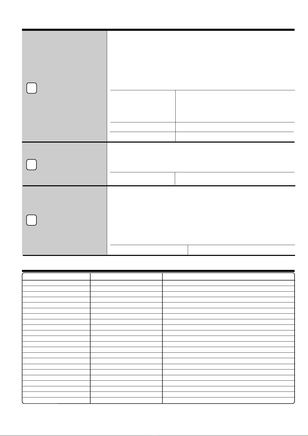
Indice - Index - Table - Indice - Indice - Index
Italiano
Certificato di garanzia 3
Principio di funzionamento 4
Avvertenze Generali 4
Schema dei segnali in entrata ed uscita alla centralina 5
Programmazione base 5
Descrizione componenti 6 - 7
Descrizione piedinatura del connettore 7
SCHEMA ELETTRICO DI INSTALLAZIONE 8
Procedura per la messa in funzione 9
English
Warranty certificate 10
Principle Function 11
General Warnings 11
Input and output signals from the panel box 12
Basic Programming 12
Components Description 13 - 14
Description of connector wire layout 14
ELETTRICAL DIAGRAM INSTALLATION 15
Setting at work procedure 16
Français
Certificat de garantie 17
Principe de fonctionnement 18
Instructions générales 18
Schémas des signaux en entrée et sortie 19
Programmation base 19
Description composants 20 - 21
Description disposition des fils dans le connecteur 21
SCHEMA ELECTRIQUE DINSTALLATION 22
Procédure de mise en fonction 23
Español
Certificado de garantìa 24
Principio de funcionamiento 25
Advertencias generales 25
Esquema de las señales de entrada y salida a la caja de mando 26
Programación de base 26
Descripción de los componentes 27 - 28
Descripción de la disposición de los hilos en el conector 28
ESQUEMA ELECTRICO DE INSTALACION 29
Procedimiento para la puesta en función 30
Potuguês
Certificado de garantia 31
Princípios de funcionamento 32
Advertências gerais 32
Esquema dos sinais de entrada e saída da centralina 33
Programação de base 33
Descrição dos componentes 34 - 35
Descrição da composição dos fios no conector 35
ESQUEMA ELÉCTRICO DE INSTALAÇÃO 36
Procedimento para o funcionamento 37
Deutsch
Garantiebescheinigung 38
Funktionsprinzipien 39
Allemeine Hinweise 39
Bauplan der Steuerungskasteneingangs- und -ausgangssignale 40
Grundeinstellung 40
Beschreibung der Bestandteile 41 - 42
Beschreibung der Steuerungskastenanschlüsse 42
Elektrischer Installationsplan 43
Inbetriebnahmeverfahren 44
Pag. 3
Italiano
is170 Rev. 190598 - 0
Giorno Mese Anno
Certificato di Garanzia
Gentile Cliente,
grazie per la fiducia accordata alla A.E.B. acquistando questo prodotto.L' A.E.B. sottopone tutti i suoi prodotti a severi
test di qualità; se nonostante i controlli il prodotto dovesse presentare dei malfunzionamenti, Le raccomandiamo di
rivolgersi subito all' installatore per i controlli o gli interventi del caso.
- Norme generali di garanzia
A.E.B. garantisce, il buon funzionamento di questo prodotto e la sua immunità da vizi e difetti costruttivi. Se durante il
periodo di garanzia il prodotto risultasse difettoso, A.E.B. si farà carico delle riparazioni o sostituzioni del caso,
affidandone l'esecuzione preferibilmente all'originario installatore, altrimenti a chi designato di comune accordo. Le
sostituzioni dei pezzi difettosi avverranno franco stabilimento A.E.B. e con spese di spedizione a carico del
destinatario. Per gli accessori od i componenti non costruiti da A.E.B. valgono soltanto le garanzie riconosciute dai terzi
produttori. La presente garanzia è l'unica prestata da A.E.B., restandone pertanto esclusa ogni altra. Nessuna
responsabilità, se non in caso di dolo o colpa grave, potrà far carico ad A.E.B. per danni a persone o cose a chiunque
derivati da malfunzionamenti del prodotto. La presente garanzia è operativa soltanto per chi in regola con i pagamenti.
- Condizioni
La garanzia verrà riconosciuta per un periodo di
12 mesi dalla data di installazione
solo dietro presentazione di questo
certificato, che dovrà riportare il timbro dell' installatore, la data di installazione, la matricola del prodotto e la vettura su
cui il prodotto era installato, accompagnato dalla fattura o ricevuta rilasciati dall' installatore su cui sono riportate le
matricole dei prodotti installati. L'A.E.B. in mancanza di tali informazioni comunque riconosce una garanzia di
18 mesi
dalla data stampata sul prodotto con vernice indelebile
. L'A.E.B. potrà rifiutare il riconoscimento della garanzia se
queste informazioni risultassero incomplete o manomesse dopo l'acquisto. La garanzia varrà soltanto se al momento
dell' acquisto il prodotto risulta ben conservato ed integro nel suo imballaggio e confezionamento predisposti da A.E.B.,
che sono gli unici ad assicurarne provenienza ed un' adeguata protezione.
- Esclusioni della garanzia
Questa garanzia non copre:
a)
Controlli periodici, manutenzioni, riparazioni o sostituzione di pezzi dovuti al normale deterioramento ;
b)
Malfunzionamenti dovuti a incuria, cattiva installazione, uso improprio o non conforme alle istruzioni tecniche
impartite ed in genere ogni malfunzionamento non riconducibile a vizi e difetti costruttivi del prodotto e dunque a
responsabilità di A.E.B.;
c)
Prodotti da chiunque modificati, riparati, sostituiti, montati e comunque manomessi senza la preventiva
autorizzazione scritta di A.E.B.;
d)
Incidenti, originati da cause di forza maggiore od altre cause (ad es. acqua, fuoco, fulmine, cattiva aereazione, ecc.)
non dipendenti dalla volontà di A.E.B..
Chiunque dovrà astenersi dal rivendere od installare prodotti affetti da vizi o difetti costruttivi riconoscibili con
la normale diligenza. Il Foro competente per eventuali controversie in ordine all' interpretazione ed esecuzione
di questa garanzia è unicamente quello di Reggio Emilia.
MODELLO VETTURA :
MATRICOLA :
DATA DI INSTALLAZIONE :
Timbro dell'installatore

Italiano
Pag. 4
is170 Rev. 190598 - 0
Principio di funzionamento
Il
" VOILA PLUS "
è un sistema programmabile e autoadattativo gestito da microprocessore, in grado di
mantenere il rapporto stecchiometrico ARIA / GAS ( Metano o Gpl ) in ogni condizione di funzionamento, entro il
valore ottimale, sfruttando i segnali di
sonda lambda, numero giri motore e posizione farfalla acceleratore
( T.P.S. )
. La regolazione del GAS viene fatta tramite un attuatore elettromeccanico da porsi lungo il tubo che collega
il riduttore di pressione al miscelatore. L’attuatore elettromeccanico è composto da un corpo in plastica con foro
calibrato per il passaggio del GAS, su cui è alloggiato un motore passo
-
passo in grado di dosare a seconda della
necessità, la giusta quantità di GAS.
Essendoquestounsistemaautoadattativononnecessitadiaggiustamentiperiodici.L’unicaregolazionemanuale
da effettuare è quella del minimo sul riduttore ed è importante che sia fatta con la massima precisione.
Il
" VOILA PLUS "
controlla la carburazione anche al minimo, ma se la regolazione del riduttore non è ottimale (
miscela
troppo ricca otroppo magra
) non può effettuare delle grosse variazioni, il suo scopo è quello di effettuare solo una
regolazione fine della carburazione al minimo.
Per adattare il
" VOILA PLUS "
alle diverse caratteristiche di ogni singola vettura e alle diverse condizioni di
funzionamento è possibile modificare diversi parametri collegandosi alla centralina tramite un'
interfaccia seriale
( Cod. AEB 001 ) ed un
computer
su cui va installato un
software dedicato
( Cod. AEB003 ). Per il controllo della sola
carburazione è sufficiente il TESTER ( Cod. AEB210ESP ).
La centralina del
" VOILA PLUS "
è inoltre in grado, se opportunamente programmata di simulare il
funzionamento della Sonda Lambda di tutte le vetture senza dover aggiungere altri emulatori di Sonda Lambda esterni.
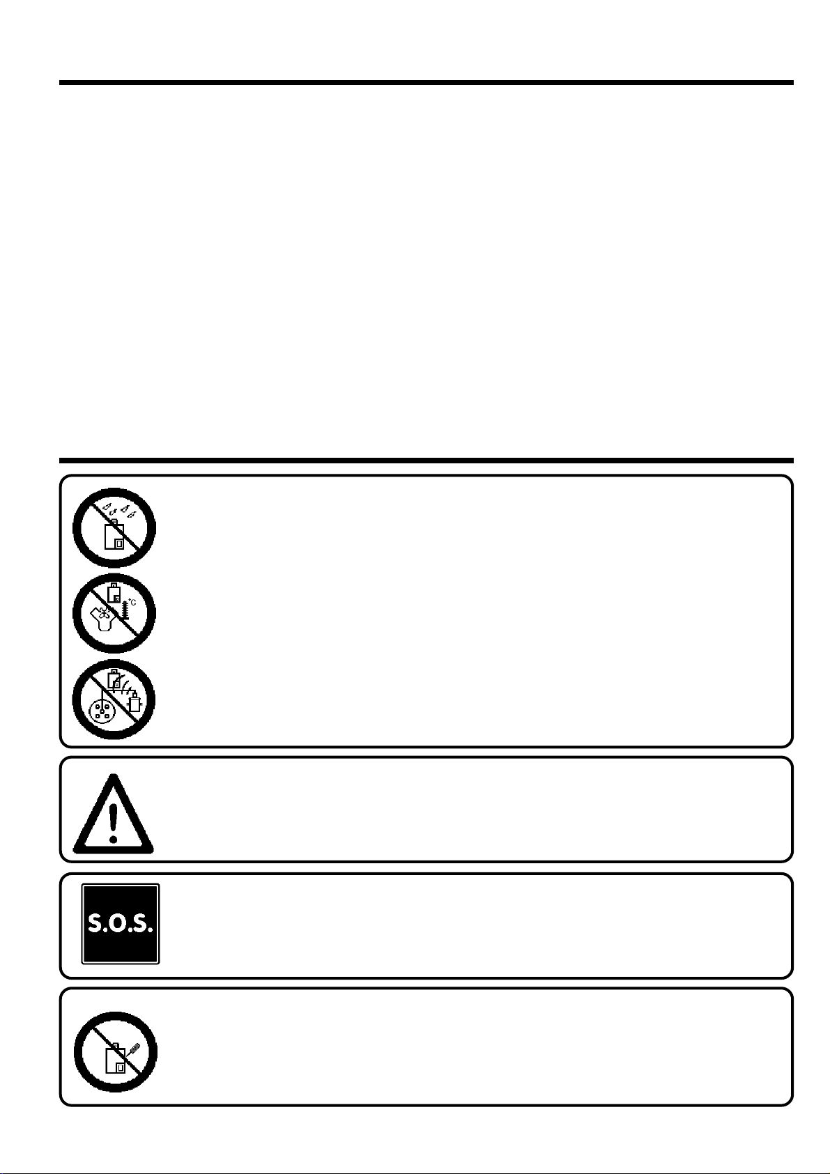
Avvertenze generali
Come fissare il Sistema Feedback :
- LONTANO da possibili INFILTRAZIONI D'ACQUA
- LONTANO da ECCESSIVE FONTI DI CALORE ( esempio collettori di scarico )
- LONTANO dai CAVI DELL'ALTA TENSIONE
Fare delle buone connessioni elettriche evitando l'uso dei " RUBACORRENTE "
Si tenga presente che la migliore connessione elettrica è la saldatura debitamente isolata
Avvisare il cliente che se salta il fusibile dell'impianto a GAS, il Sistema Feedback ripristina i
collegamenti dei dispostivi a cui e collegato.
Non aprire per nessun motivo la scatola del Sistema Feedback soprattutto con il motore in moto o il quadro
inserito, onde evitare danni irreparabili.
L'A.E.B. declina ogni responsabilità per danni a cose e persone derivati dalla
manomissione del propio dispositivo da parte di personale non autorizzato con la
conseguente perdita di GARANZIA.
Pag. 5
Italiano
is170 Rev. 190598 - 0
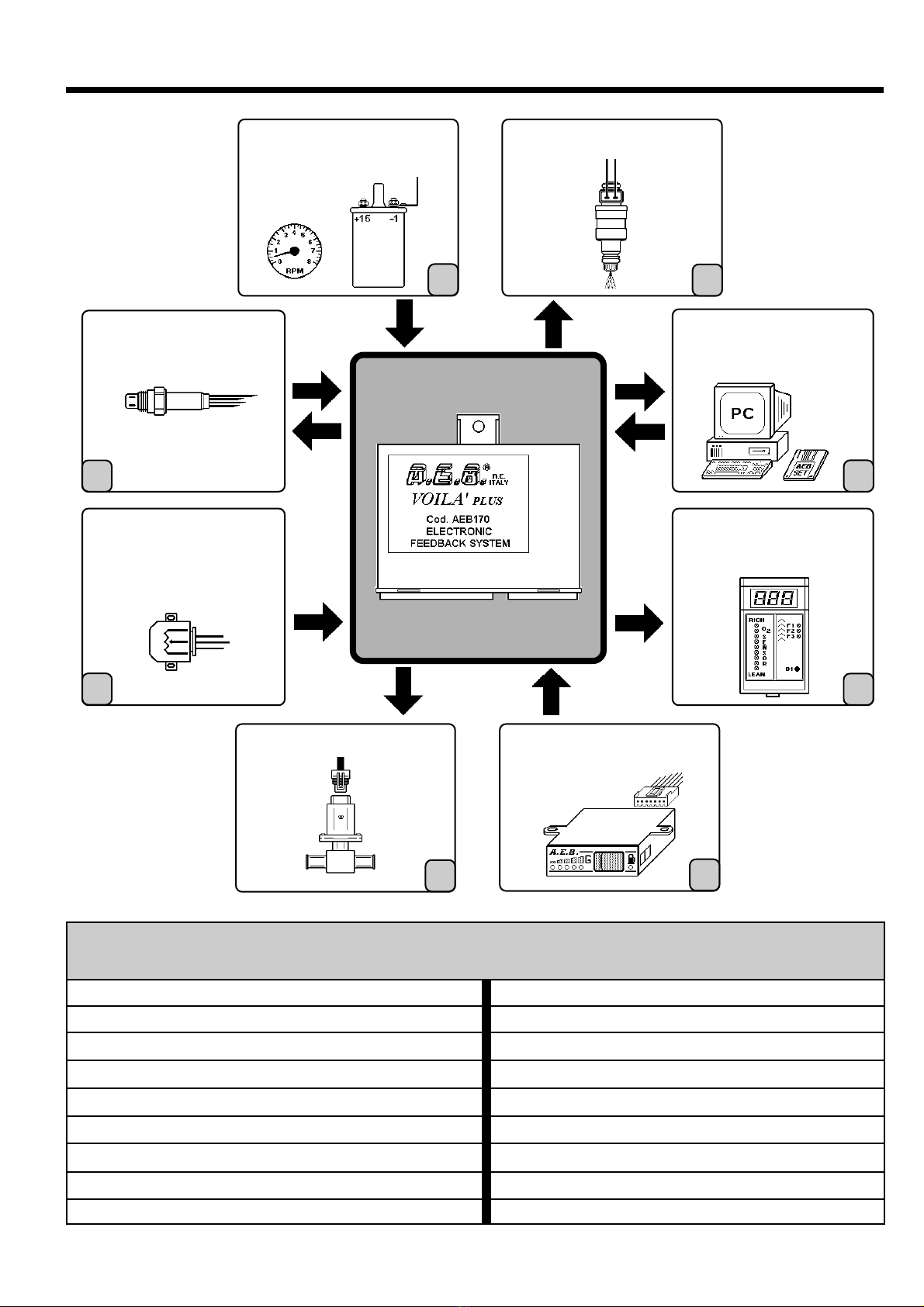
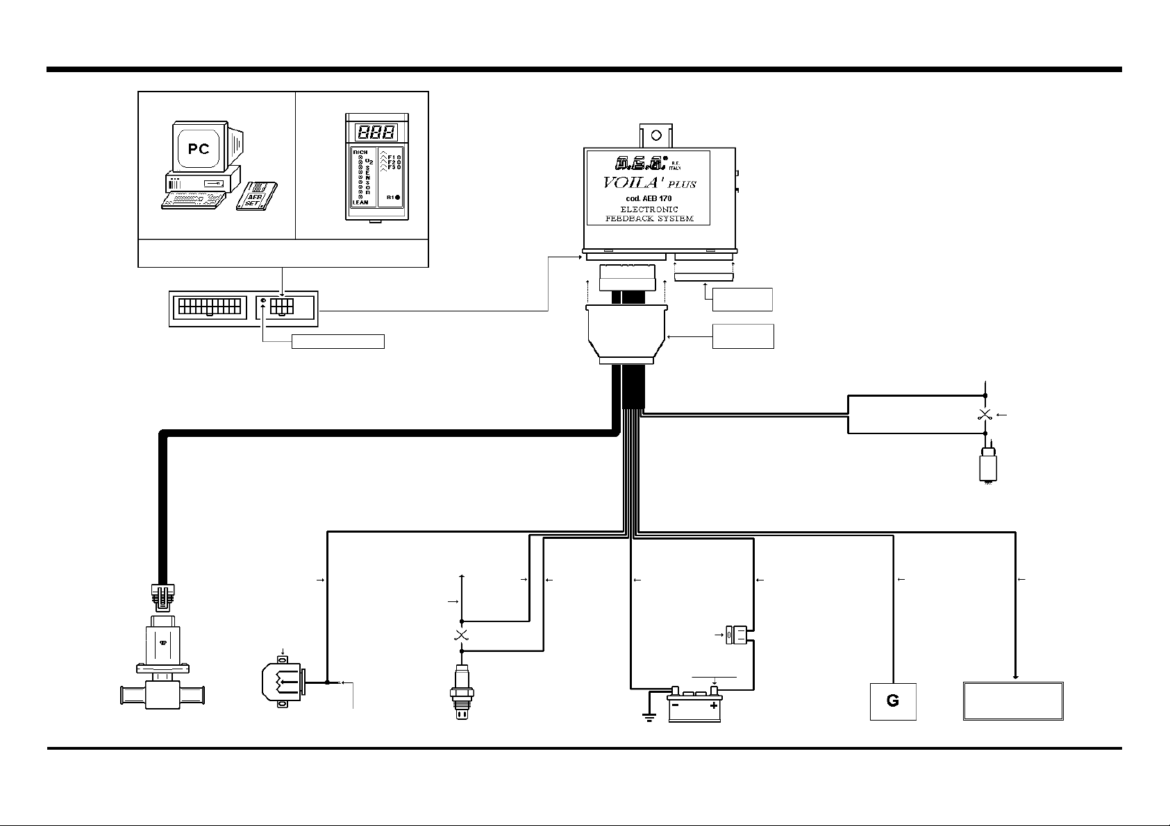
Schema dei segnali in entrata e in uscita alla centralina
MOTORE PASSO - PASSO COMMUTATORE
( TPS )
SENSORE POSIZIONE
ACCELERATORE
SONDA LAMBDA
TESTER PER
VISUALIZZAZIONE
PARAMETRI
PROGRAMMAZIONE E
VISUALIZZAZIONE
PARAMETRI
STACCA INIETTORI
NEGATIVO BOBINA O
SEGNALE CONTAGIRI
78
1
2
3
4
5
6
Programmazione base del " VOILA PLUS "
Tipo accensione Bibobina
Segnale giri Standard
Tempo sovraposizione 0.4 secondi
Tipo T.P.S. Lineare 0 - 5V
Tipo Sonda Lambda 0 - 1V
Tipo emulazione Onda quadra
Ritardo lettura sonda 5 secondi
Massima apertura attuatore 240 passi
Minima apertura attuatore 20 passi
Posizione in affondata disinserito
T.P.S. per affondata -----------
Cut - off Disinserito
Giri stacca cut - off -----------
Posizione attuatore in cut - off -----------
Imposta default fisso Disinserito
Tipo guida Normale
Isteresi sul minimo T.P.S. 0.14V
Cancellazione eeprom
Italiano
Pag. 6
is170 Rev. 190598 - 0
Descrizione componenti
Il T.P.S. è collegato meccanicamente alla farfalla dell'acceleratore, ed invia alla
centralina di iniezione un segnale variabile in tensione proporzionale all'angolo di
apertura della farfalla . Il " VOILA PLUS " sfrutta la stessa informazione per il controllo
della carburazione a GAS.
-Il T.P.S. è DI TIPO LINEARE
quando la tensione aumenta o diminuisce
gradualmente al variare della posizione della farfalla.
-Il T.P.S. è DI TIPO SWITCH
quando la tensione passa dal minimo al
massimo o viceversa non appena viene premuto anche di poco l'acceleratore.
-Il T.P.S. di un MONOBOSCH
ha il potenziomentro farfalla con due fili di segnale che
variano in modo diverso l'uno dall'altro. Selezionare la funzione
MONOBOSCH
solo se
ci si collega al filo
N° 2 è comunque consigliata la connessione al filo N° 4.
- La centralina può funzionare anche se non è presente il T.P.S., è comunque
consigliabile quando possibile connettere questo filo.
FUNZIONI PROGRAMMABILI DA COMPUTER
Tipo T.P.S.
0 - 5 V lineare
5 - 0 V lineare
0 - 12 Vswitch
12 - 0 V switch
T.P.S. monobosch
senza T.P.S.
T.P.S. per affondata
da 0 a 5V
Isteresi sul minimo T.P.S.
da 0 a 0,5V
Il motore passo - passo ha il compito di regolare il flusso del GAS aspirato dal motore,
mantenendo la carburazione in ogni condizione di funzionamento entro i valori ottimali
per far questo la centralina del " VOILA PLUS " elabora i segnali di T.P.S. , Sonda
lambda e Giri motore.
FUNZIONI PROGRAMMABILI DA COMPUTER
Massima apertura attuatore
da 0 a 255 passi
Minima apertura attuatore
da 0 a 255 passi
Posizione in affondata
da 0 a 240 passi
Cut - off
disinserito - inserito
Giri stacca cut - off d
a 1.200 a 5.000 rpm
Posizione attuatore in cut - off
da 20 a 240 passi
Imposta DEFAULT fisso
da 0 a 240 passi - disinserito
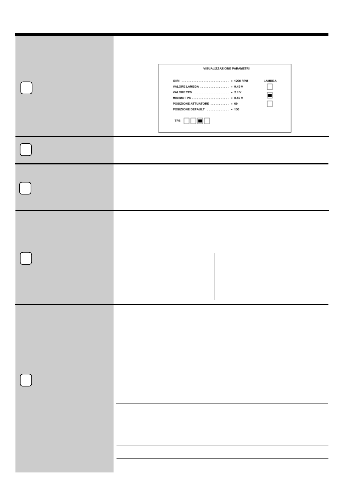
Installando l'apposito software su di un computer è possibile connettersi
tramite l'interfaccia seriale alla centralina del " VOILA PLUS " per modificare i vari
parametri e visualizzarne il funzionamento.
2
Tester visualizzazione
parametri
Programmazione
e visualizzazione
parametri
1
Commutatore
3
Con il Tester è possibile visualizzare :
- posizione motorino passo - passo tramite il display a 3 cifre
- funzionamento sonda lambda.
( TPS )
Sensore posizione
acceleratore
5
Motore
passo - passo
4
Il Commutatore non è fornito nella stessa confezione del " VOILA PLUS ",
DEVE ESSERE ACQUISTATO SEPARATAMENTE.
Il collegamento al filo BLU del commutatore ( uscita servizi GAS ) è necessario per
abilitare il " VOILA PLUS " solo durante il funzionamento a GAS. Durante il
funzionamento a BENZINA, saranno ripristinati tutti i collegamenti come in origine.
Pag. 7
Italiano
is170 Rev. 190598 - 0
Descrizione componenti
Sonda Lambda
6
La Sonda Lambda fornisce l'informazione della quantità di ossigeno presente nei gas di
scarico per regolare di conseguenza la carburazione. In presenza di molto ossigeno
avremo una carburazione tendenzialmente MAGRA ( poco GAS ) al contrario in
presenza di poco ossigeno avremo una carburazione GRASSA ( molto GAS ).
Per individuare il filo del segnale di una sonda lambda, si consiglia di utilizzare un
multimetro meglio se digitale, impostare lo strumento per misurare la tensione
continua, mettere un puntale a massa ( batteria ) e con l'altro puntale verificare quale
dei fili ha una tensione variabile, è importante che la vettura si sia calda prima di
effettuare la misura.
FUNZIONI PROGRAMMABILI DA COMPUTER
Tipo sonda lambda
0- 1V
0 - 5 V tipo A ( attualmente non utilizzata )
0 - 5 V tipo B
5 - 0 V tipo A
5 - 0 V tipo B ( attualmente non utilizzata )
0.8 - 1.6 V
Tipo emulazione
massa - onda quadra - costruita - circuito aperto
Ritardo lettura sonda
da 5 a 1275 sec.
All'interno del
" VOILA PLUS "
è stato predisposto un relay con la funzione di stacca
iniettori, per quelle vetture dove la centralina d'iniezione non effettua nessuna
diagnosi sull'iniezione. Nel momento della commutazione da BENZINA a GAS, è stato
previsto un tempo
( di sovrapposizione )
in cui non viene bloccato immediatamente il
funzionamento degli iniettori, questo per permettere al gas di uscire dal riduttore ed
arrivare all'aspirazione, evitando buchi di alimentazione con conseguenti ritorni di
fiamma.In questo modo durante la commutazione si avrà per qualche secondo la
sovrapposizione dei due carburanti ( BENZINA e GAS ) per un tempo regolabile.
FUNZIONI PROGRAMMABILI DA COMPUTER
Tempo di sovrapposizione
Regolabile da 0sec. a 1sec.
Stacca iniettori
8
Il segnale dei giri motore può essere prelevato direttamente dal negativo della
bobina o dal segnale del contagiri,
è comunque importante che sia collegato perchè
la centralina del " VOILA PLUS " possa funzionare correttamente.
FUNZIONI PROGRAMMABILI DA COMPUTER
Tipo accensione
4 - 5 - 6 - 8 ( cilindri ) - bibobina - monobobina
Segnale giri
Standard - Segnale debole
Negativo bobina
o
segnale contagiri
7
PIN. n° COLORE FILO UTILIZZO
1 AZZURRO Ø 0.5 Controllo motore passo - passo ( A )
2 VIOLA Ø 0.5 Controllo motore passo - passo ( D )
3 VUOTO - - - - - - - - - - - - - - - - - - - - - - - - - - - - - - - - - - -
4 VUOTO - - - - - - - - - - - - - - - - - - - - - - - - - - - - - - - - - - -
5 BLU - GIALLO AlfilosegnaledelT.P.S.
6 VUOTO - - - - - - - - - - - - - - - - - - - - - - - - - - - - - - - - - - -
7 GIALLO Interruzzioneiniettori
8 NERO Massa
9 VUOTO - - - - - - - - - - - - - - - - - - - - - - - - - - - - - - - - - - -
10 VUOTO - - - - - - - - - - - - - - - - - - - - - - - - - - - - - - - - - - -
11 VUOTO - - - - - - - - - - - - - - - - - - - - - - - - - - - - - - - - - - -
12 BIANCO Ø 0.5 Controllo motore passo - passo ( B )
13 ARANCIO Ø 0.5 Controllo motore passo - passo ( C )
14 VIOLA Al filo segnale sonda lambda ( lato sonda )
15 GRIGIO Al filo segnale sonda lambda ( lato centralina )
16 MARRONE Giri motore
17 VUOTO - - - - - - - - - - - - - - - - - - - - - - - - - - - - - - - - - - -
18 GIALLO Interruzioneiniettori
19 BLU Alla posizione GAS del commutatore ( uscita servizi GAS )
20 ROSSO - NERO + 12V Batteria
21 VUOTO - - - - - - - - - - - - - - - - - - - - - - - - - - - - - - - - - - -
22 VUOTO - - - - - - - - - - - - - - - - - - - - - - - - - - - - - - - - - - -
Descrizione piedinatura del connettore
Schema di installazione Italiano
Pag.8
is170 Rev. 190598 - 0
AL PERSONAL COMPUTERS
O AL TESTER DI CONTROLLO
LED DI CONTROLLO
TAPPO DI
PROTEZIONE
CUFFIA DI
PROTEZIONE
ATTUATORE
MOTOREPASSO- PASSSO FILO DEL SEGNALE
T.P.S.
BLU - GIALLO
FILO SEGNALE
SONDA LAMBDA
SONDA LAMBDA
GRIGIO
ALLA CENTRALINA
D'INIEZIONE VIOLA NERO
FUSIBILE
MAX 7,5A
+12V
BATTERIA
MASSA
ROSSO - NERO BLU
ALLA POSIZIONE GAS
DEL COMMUTATORE
AL CONTAGIRI O
AL NEGATIVO BOBINA
MARRONE
INTERRUZIONE
DELL'INIEZIONE
GIALLO
GIALLO
T.P.S.

Pag. 9
Italiano
is170 Rev. 190598 - 0
Procedura per la messa in funzione
1 )
Eseguire le connessioni elettriche come da schema, avendo le seguenti precauzioni :
•tenere i fili del
" VOILA PLUS "
il più lontano possibile dai cavi dell'alta tensione, onde evitare che scariche di
alta tensione disturbino i segnali deboli come quello della Sonda Lambda e TPS, provocando malfunzionamenti del
" VOILA PLUS "
e della centralina originale d'iniezione ;
•collegare il filo NERO di massa al polo negativo della batteria. Si tenga presente che il riferimento della massa è
fondamentale per un buon funzionamento del
" VOILA PLUS "
;
•per le connessioni non utilizzare i rubacorrente, la migliore connessione è la saldatura debitamente isolata o gli
appositi faston.
Una connessione effettuata senza i dovuti accorgimenti può provocare :
•falsi contatti con conseguenti malfunzionamenti del " VOILA PLUS " e della vettura ;
• possibili corto circuiti, con il danneggiamento dei dispostivi elettronici.
2 )
Collegare il cablaggio della centralina e del motorino passo - passo .
3 )
Inserire i fusibili, verificare che il Led ROSSO di controllo della centralina si accenda per qualche secondo e poi si
spenga. La centralina effettua un azzeramento dell'attuatore.
• non sostituire mai
il fusibile in dotazione da 7,5A con uno di amperaggio maggiore. Ciò potrebbe provocare
danni irreparabili sia al
" VOILA PLUS "
che alla vettura.
4 )
Se necessario programmare i parametri della centralina tramite un computer e l'apposito software.
5 )
Con il TESTER di regolazione collegato al
" VOILA PLUS "
, avviare la vettura a benzina ed attendere che i LED
VERDI, GIALLI e ROSSI sulla sinistra del tester si accendano alternativamente. A questo punto la Sonda Lambda
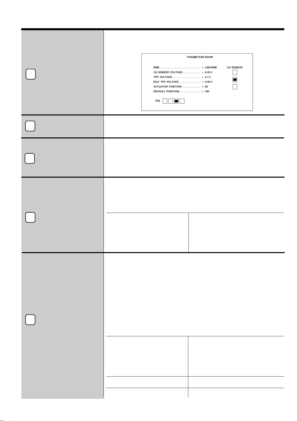
si è scaldata e ha cominciato a funzionare. Collegando invece il COMPUTER al "
VOILA PLUS "
avviare la
vettura a benzina ed attendere che il
valore lambda
e la
barra grafica
sulla destra del monitor inizino ad
oscillare. A questo punto la Sonda Lambda si è scaldata e ha cominciato a funzionare.
Se non si verificano queste condizioni controllare che :
• il filo GRIGIO e VIOLA siano stati collegati correttamente e non invertiti di posizione ( vedi schema );
• la MASSA sia collegata correttamente, e non ci siano falsi contatti;
• la Sonda Lambda potrebbe essere danneggiata ed è necessario sostituirla.
6 )
Commutare la vettura a GAS ( Gpl o Metano ) ed effettuare alcune accelerate e decelerate avendo cura di non far
spegnere il motore.In questa condizione il Led ROSSO di controllo della centralina è acceso al minimo e
lampeggia fuori minimo, ciò indica che la centralina non ha ancora memorizzato i parametri della carburazione.
7 )
Portare ora il regime di rotazione del motore a circa 2.500 - 3.000 g / min. ed attendere che il Led ROSSO di
controllo smetta di lampeggiare A questo punto la centralina ha memorizzato i parametri della carburazione ed il
Led ROSSO fornisce le seguenti informazioni :
• LED ROSSO acceso = T.P.S. al minimo
• LED ROSSO spento = T.P.S. fuori minimo
8 )
Portare il motore al minimo e regolare il minimo del riduttore verificando con il COMPUTER o il TESTER che la
carburazione sia corretta. La posizione ottimale del motorino passo - passo durante il funzionamento a GPL è
compresa tra i 50 - 100 passi mentre nel funzionamento a METANO è compresa tra i 70 - 150 passi. Se la
posizione del motorino passo - passo si discosta molto da questi valori è consigliabile verificare il miscelatore o il
funzionamento del riduttore.
9 )
A questo punto è consigliabile effettuare un test di guidabilità su strada, lasciando inserito o il COMPUTER o il
TESTER per verificare la carburazione con la vettura in movimento.
N.B. STACCANDO LA BATTERIA VENGONO CANCELLATI DALLA MEMORIA DELLA CENTRALINA
DEL " VOILA' PLUS " SOLO I DATI RELATIVI ALLA CARBURAZIONE.
TUTTE LE IMPOSTAZIONI FATTE TRAMITE COMPUTER RIMARRANO INVARIATE, QUESTE SARA'
POSSIBILE MODIFICARLE SOLO CON IL COMPUTER.
English
is170 Rev. 190598 - 0 Pag. 10
Warranty Certificate
- Dear Customer,
Thank you for the trust given to A.E.B. in buying this product. All A.E.B. products are subjected to severe quality checks.
If, nevertheless, these should have some malfunctions, we recommend you to immediately refer to the installer for any
necessary check-up and intervention.
- General Warranty terms
A.E.B. warrants that the product is in good working order and free of construction flaws and defects. Any defect arising
during the warranty period, shall be repaired or replaced, at A.E.B.’s cost, by the original installer or by employing
someone else agreed in common. The replacement of defected parts shall be supplied ex-works and dispatch fees are at
consignee' charge. For all those accessories and components not of A.E.B. production, the recognised warranty terms
are those given by the third party constructor. This warranty is the only one given by A.E.B., and therefore excludes any
other. A.E.B. is liable to no obligations owing to harm to persons or things due to malfunction of the product, except in
case of fraud or bad fault. This warranty is valid only for those whose payments are up to date.
- Conditions
This warranty shall remain valid for a period of 12 months from date of installation and against presentation of this
certificate. The certificate must have the installer stamp and must mention installation date, product serial number and
vehicle on which the product has been installed. The invoice or receipt given by the installer must also be attached to the
certificate and must mention the serial numbers of the installed products. If the above information is missing, A.E.B. will,
nevertheless, warrant the product for a period of 18 months from the date printed, with permanent paint, on the
product. A.E.B. may refuse to recognise the warranty if this information is incomplete or tampered with after purchase.
The warranty is valid only if, at moment of purchase, the product is well kept and whole in its package and wrapping,
prearranged by A.E.B, and which ensures its origin and an adequate protection.
- Warranty Exclusions
This warranty does not cover:
a) Periodical controls, maintenance, repairs and replacement due to normal wear;
b) Malfunction due to negligence, bad installation, improper use or not in accordance with the technical instructions
provided and in general any malfunction not owing to product flaws or defects and therefore leading to A.E.B.
responsibility.
c) Products that have been modified, repaired, replaced, assembled and in any case tampered with without prior written
approval of A.E.B;
d) Accidents caused by “force majeure” reasons or other ( for e.g. water, fire, lightning, poor ventilation etc.) not
depending on A.E.B.’s will.
Nobody must resell or install products with flaws or defects that are recognisable by ordinary care. The place of
jurisdiction for any controversy concerning the interpretation and execution of this warranty is only Reggio
Emilia.
VEHICLE MODEL :
SERIAL NUMBER :
Day Month Year
INSTALLATION DATE :
Installer Stamp
English
is170 Rev. 190598 - 0 Pag. 11
Principle Functions
“Voila Plus” is a programmable and self adaptive system controlled by microprocessors, which are able to keep
a stoichiometric AIR/GAS ratio (Methane or Gpl) in any sort of working condition, within optimum values. It makes use of
the
lambda feeler, motor rev number and throttle valve position (T.P.S.
) signals. The GAS adjustment is obtained
through an electromechanical actuator placed along the pipe that connects the pressure reducer to the mixer. The
electromechanical actuator is composed of a plastic body with calibrated holes for the GAS way, and on which a stepper
motor, capable of dosing when necessary the correct amount of GAS needed, is placed.
This being a self-adaptive system it needs no periodical adjustments. The only manual adjustment to be carried
out is that of the minimum on the pressure reducer and it is very important that it is done with maximum precision.
“
VOILA PLUS
”controls the carburetion even at minimum running, but if the pressure reducer adjustment is not at its
best (a too rich or too poor mix) it can not carry out meaningful variations. Its task is that of carrying out only one fine
carburetion adjustment at minimum running.
To adapt “
VOILA PLUS
”to the different characteristics of each single vehicle and to different working
conditions, it is possible to modify several parameters connecting oneself to the central system through a
serial interface
( Code AEB 001 ) and a
computer
with an appropriate installed
software
( Code AEB003 ). For the control of the
carburetion the TESTER ( Code AEB210ESP ) is sufficient.
The “
VOILA PLUS"
panel box, if correctly programmed, is able to simulate the working of the Lambda Feeler of
all vehicles, without having to add any other external Lambda Feeler emulator.
General warnings
How to fix the Feedback System:
- FAR FROM possible WATER INFILTRATIONS
- FAR FROM EXCESSIVE HEAT SOURCES ( exhaust muffler )
- FAR FROM HIGH VOLTAGE CABLES
Perform good electrical connections avoiding the use of “CURRENT BLANKERS”. Keep in mind
that the best electric connection is done with insulated welding.
Warn the Customer that if the fuse of the GAS installation should trip, the Feedback System
will resets the connections of the devices to which it is connected.
In order to avoid irreparable damage, the Feedback System box must never be opened for any
reason, especially when engine is running and panel is on.
A.E.B. shall not be held responsible for any damages or harm to things and persons owing
to the tampering of the device by non - authorised personnel and thus causing WARRANTY
loss.

English
is170 Rev. 190598 - 0 Pag. 12
78
1
2
3
4
5
6
Ignition type Coilpack
RPM signal type Standard
Overlap time 0.4 seconds
TPS type Linear 0 - 5v
O2 sensor type 0 - 1v
O2 simulation Square wave
Open loop starting time 5 seconds
Maximum actuator position 240 steps
Minimum actuator position 20 steps
PROGRAMMING AND
PARAMETERS DISPLAY
TESTER FOR
PARAMETERS
DISPLAY
CHANGE-OVER
SWITCH
STEPPER MOTOR
(TPS)
THROTTLE POSITION
SENSOR
O2 SENSOR
NEGATIVE COIL
OR
REV COUNTER
INJECTOR DETACHING
Position for overboost Off
TPS voltage for overboost -----------
Cut-off Off
RPM turn-off cut-off -----------
Actuator position in Cut-off -----------
Default position locked Off
Driving type Norm.
TPS Hysteresis 0.14V
Erising EEPROM
“VOILA PLUS” Basic Programming
Input and output signals diagram to the panel box
English
is170 Rev. 190598 - 0 Pag. 13
Component description
T.P.S. is mechanically connected to the throttle valve, and sends a voltage signal to the
injection panel box that varies in proportion with the throttle opening angle. “VOILA PLUS”
uses the same information for the GAS carburetion control.
-
T.P.S. is LINEAR TYPE
when voltage, depending on change of throttle position,
gradually increases or decreases .
-
T.P.S. is SWITCH TYPE
when the voltage goes from minimum to maximum or vice versa
no sooner the accelerator is slightly pressed.
-
T.P.S. of a MONOBOSCH
has the potentiometer throttle with two signal wires that are
different from each other. Select the MONOBOSCH function only if you are connected to
wire N. 2. It is recommended, nevertheless, connecting wire N. 4 as well.
-
The panel box can work even if the T.P.S. is not present, it is however
recommended to connect this wire whenever possible.
2
Tester parameters
display
1
Change over switch
3
(TPS)
Trottle position sensor
5
Stepper motor
4
With the Tester it is possible to display :
- stepper motor position through a three figure display.
- Lambda feeler position.
TPS type
Linear 0 - 5v
Linear 5 - 0v
Switch 12 - 0v
Switch 0 - 1v
MONOBOSCH
Without T.P.S.
TPS voltage for overboost
from 0 to 5V
TPS hysteresis
from 0 to 0,5V
The change over switch is not included in the “VOILA PLUS” package, IT HAS TO
BE BOUGHT SEPARATELY.
The connection to the BLUE wire of the change over switch (GAS exit service) is
necessary for the activation of the “VOILA PLUS” only during GAS operation. During the
PETROL operation, all connections will be reset as from starting point.
If an appropriate software is installed in a computer, it is possible to connect oneself,
through the serial interface, to the “VOILA PLUS” panel box thus allowing modification of
various parameters and function display.
Programming
and
parameters display
PROGRAMMABLE COMPUTER FUNCTIONS
The stepper motor has the task of adjusting the GAS flow inducted by the engine while
keeping carburetion within optimum values, in every working condition. To do so, the “VOILA
PLUS” panel box elaborates the T.P.S., Lambda Feeler and Rev motors signals.
PROGRAMMABLE COMPUTER FUNCTIONS
Maximum actuator position
Minimum actuator position
Position for overboost
Cut - off
RPM turn-off cut-off
Actuator position in cut - off
DEFAULT position locked
from 0 to 255 pitches
from 0 to 255 pitches
from 20 to 240 pitches
on - off
from 1.200 to 5000 rpm
from20 to 240 steps
from 0 to 240 steps-disconnected
English
is170 Rev. 190598 - 0 Pag. 14
Computer Programmed Functions
Oxigen sensor
6
The Lambda feeler supplies information on the amount of oxygen present in the exhaust
gas to consequently adjust carburetion. In the presence of a lot of oxygen we would have
a basically POOR carburetion (little GAS), on the contrary in the presence of little oxygen
we would have a RICH carburetion (a lot of GAS). In order to identify the wire of a lambda
feeler, we suggest using a multimeter, better if digital. Set the instrument to measure
continuous voltage, set a rod to earth (battery) and with the other rod check which wire has
a variable voltage. It is important that the vehicle is warm before measuring is done.
A relay has been put inside the ”VOILA PLUS” (only for those vehicles whose panel box
performs no diagnoses on injection) and its function is that of injector detaching. When
switching on from PETROL to GAS, there is a time foreseen
(called overlapping)
in
which injector functioning is not immediately locked. This in order to allow the GAS to exit
from the reducer and reach induction, thus avoiding feed gaps and consequently
backfiring. In this way, during switching the two fuels (PETROL and GAS) will overlap for
a time that can be adjusted.
Injector disconnect
8
The engine rpm signal can be taken directly from the coil negative or from the revolution
counter signal.
It is, however, important that it is connected to the “VOILA PLUS”
panel box in order to ensure correct operation.
Negative coil
or
rev. counter signal
7
N° PIN WIRE COLOUR USE
1 LIGHT-BLUE 0.5 Stepper motor control (A)
2 VIOLET 0.5 Stepper motor control (D)
3 VOID - - - - - - - - - - - - - - - - - - - - - - - - - - - -
4 VOID - - - - - - - - - - - - - - - - - - - - - - - - - - - -
5 BLUE-YELLOW To TPS wire signal
6 VOID - - - - - - - - - - - - - - - - - - - - - - - - - - - -
7 YELLOW Injector Cut-off
8 BLACK Earth
9 VOID - - - - - - - - - - - - - - - - - - - - - - - - - - - -
10 VOID - - - - - - - - - - - - - - - - - - - - - - - - - - - -
11 VOID - - - - - - - - - - - - - - - - - - - - - - - - - - - -
12 WHITE 0.5 Stepper motor control (B)
13 ORANGE 0.5 Stepper motor control (C)
14 VIOLET To lambda feeler wire signal (feeler side)
15 GREY Tolambdafeelerwiresignal(panel box side)
16 BROWN EngineR.P.M.
17 VOID - - - - - - - - - - - - - - - - - - - - - - - - - - - -
18 YELLOW Injector cut off
19 BLUE Change-over switch GAS position (Gas service exit)
20 RED - BLACK + 12V Battery
21 VOID - - - - - - - - - - - - - - - - - - - - - - - - - - - -
22 VOID - - - - - - - - - - - - - - - - - - - - - - - - - - - -
Description of connector wire layout
Ignition type
4 - 5 - 6 - 8 (cyl.) – coilpack – one coil for cyl.
RPM signal time
Standard - small signal.
COMPUTER PROGRAMMED FUNCTIONS
COMPUTER PROGRAMMED FUNCTIONS
COMPUTER PROGRAMMED FUNCTIONS
Overlap time
adjustable from O sec. to 1sec
0-1V
0 - 5V A type (actually not used)
0 - 5V B type
5 - 0V A type
5 - 0V B type (actually not used)
0,8 - 1,6V
O2 sensor type
O2 simulation
Open loop starting time
Always lean - square wave, standard or build wave-
O2 sensor open circuit.
from 5 a 1275 sec.

Installation diagram English
Pag.15
is170 Rev. 190598 - 0
TO PERSONAL COMPUTER
OR CONTROL TESTER
CONTROL LED
PROTECTION
CUP
PROTECTION
CASING
STEPPER MOTOR
ACTUATOR T.P.S.
SIGNAL WIRE
BLUE - YELLOW
OXIGENSENSOR
SIGNAL WIRE
OXIGENSENSOR
GRAY
TO INJECTION E.C.U.
OF THE CAR
VIOLET BLACK
FUSE
MAX 7,5A
+12V
BATTERY
GROUND
RED - BLACK BLUE
TO SWITCH
GASPOSITION
TO REVOLUTION COUNTER
OR
TO NEGATIVE COIL
BROWN
INJECTORS
DISCONNECTING
YELLOW
YELLOW
T.P.S.
GROUND

English
is170 Rev. 190598 - 0 Pag. 16
Setting at work procedure
1) Carry out electrical connections as per diagram and be careful to:
•keep the
“VOILA PLUS”
wires as far as possible away from the high voltage cables, this to avoid high voltage
discharges that disturb weak signals like those of the Lambda Feeler and TPS, and thus causing malfunctions of the
“VOILA PLUS”
and the original injection board system;
•Connect the BLACK earth wire to the battery negative pole. Keep in mind that the earth marking is of great
importance for a good operation of the
“ VOILA PLUS ”
;
•Avoid connections with current blankers, the best electric connection is obtained with insulated welding or with
appropriate fastons.
Connection performed without due precautions may cause :
•
false contacts leading to malfunctions of the “VOILA PLUS” and vehicle;
•
possible short circuits, with damage to the electronic devices.
2) Connect the panel box and stepper motor wiring harness
3) Plug in the fuses, check that the RED warning light of the panel box switches on for a few seconds and then off.
The panel box will set the actuator to zero.
•
never replace
the supplied 7,5A fuse with one of a higher ampere rating. This could cause irreparable damage
both to the
“VOILA PLUS”
and to the vehicle.
4) If necessary program the panel box parameters using a computer and its appropriate software.
5) With the adjustment TESTER connected to the
“VOILA PLUS”
,turn on the petrol fuelled vehicle and wait until the
GREEN, YELLOW, and RED WARNING LIGHTS, placed on the left side of the tester, turn on one after the other.
At this point the Lambda Feeler has warmed up and has started working. If instead the COMPUTER is connected to
the
“VOILA PLUS”
turn on the petrol fuelled vehicle and wait until the
lambda value
and
the graphic bar
on the
monitor right side begin to oscillate. At this point the Lambda Feeler has warmed up and has started working.
If these conditions do not occur, check that:
•the GREY and PURPLE wires have been correctly connected and their position is not inverted (see diagram);
•the EARTH is correctly connected, and that there are no false contacts;
•the Lambda Feeler could be damaged then should be replaced.
6) Switch the vehicle over to GAS (LPG or CNG) and carry out a few accelerations and decelerations making sure the
engine does not turn off. In this condition the panel box RED WARNING LIGHT will be on at minimum and will flash
when out-of-minimum, meaning that the panel box has not yet memorised the carburetion parameters.
7) Now run the vehicle at 2.500 - 3.000 rpm and wait until the RED WARNING LIGHT stops flashing. At this stage the
panel box has memorised the correct carburetion position and the RED WARNING LIGHT will indicate:
•
RED WARNING LIGHT on = T.P.S. at minimum
•
RED WARNING LIGHT off = T.P.S. out-of-minimum
8) Now bring the engine to minimum running and adjust reducer minimum, check the correct carburetion with the COM
PUTER or TESTER. The optimal position of the stepper motor during LPG operation lies between 50 - 100 pitches,
and between 70 - 150 pitches during CNG operation. If the difference between these values and the stepper motor
position is higher, it is recommended to check the proper working condition of the mixer or reducer.
9) At this stage it is recommended to carry out a road test, with COMPUTER or TESTER on, so as to check carburetion
with vehicle in movement.
NOTE. WHEN BATTERY IS REMOVED ONLY DATA REFERRING TO THE “VOILA PLUS”
PANEL BOX MEMORY ARE CANCELLED.
ALL SETTINGS DONE VIA COMPUTER REMAIN UNCHANGED.
THESE CAN BE CHANGED ONLY WITH THE COMPUTER.

Français
is170 Rev. 190598 - 0 Pag. 17
Certificat de Garantie
Cher client,
nous vous remercions de la confiance accordée à la A.E.B. en achetant ce produit. L’A.E.B. soumet tous ses produits à
de sévères tests de qualité. Si, malgré les contrôles le produit fonctionne mal, nous vous recommandons de vous
adresser tout de suite à l’installateur pour les interventions relatives.
- Règles générales de garantie
A.E.B. garanti le bon fonctionnement de ce produit et son immunité contre vices et défauts de construction. Si durant la
période de garantie le produit résultait défectueux, A.E.B. se chargerait des réparations ou substitutions dudit, en confiant
l’exécution, de préférence à l’installateur original, ou bien à qui a été désigné de commun accord. Les substitutions des pièces
défectueuses auront lieu franco établissement A.E.B. et les frais d’expédition seront à charge du destinataire.Pour les
accessoires ou les pièces non construits par .A.E.B. sont valables les seules garanties reconnues par les tiers producteurs.La
présente garantie est la seule prêtée par A.E.B., en restant donc exclue n’importe quelle autre.Aucune responsabilité, sauf en
cas de dol ou faute grave, pourra être imputée à A.E.B. pour dommages à personnes ou à choses dérivant du mauvais
fonctionnement du produit. La présente garantie est opérante seulement pour qui est en règle avec les paiements.
- Conditions
La garantie sera reconnue pour une période de
12 mois à partir de la date d’installation
exclusivement sur
présentation de ce certificat, lequel devra reporter le cachet de l’installateur, la date de l’installation, la matricule du
produit et la voiture sur laquelle le produit était installé, accompagné de la facture ou du reçu fourni par l’installateur sur
lequel sont reportées les matricules des produits installés. L’A.E.B. en absence de telles informations reconnaît malgré
tout une garantie de
18 mois à partir de la date imprimée sur le produit avec un vernis indélébile
. L’A.E:B. pourra
refuser de reconnaître la garantie dans le cas d’informations incomplètes ou altérées après l’achat. La garantie n’aura
valeurquesi,aumoment de l’achat le produit estbienconservéet intègre dans son emballage et selonleconfectionnement
fait par A.E.B., lesquels sont les seuls à en garantir la provenance et une protection adéquate.
- Exclusion de la garantie
Sont exclus de la garantie:
a)
Contrôles périodiques, entretien, réparations ou substitution de pièces dûs à la normale détérioration;
b)
Problèmes de fonctionnements dûs au manque de soin, mauvaise installation, usage non approprié ou non conforme
aux instructions techniques données, et , en général tout problème de fonctionnement non imputable à vices et défauts
de construction du produit et donc à responsabilité de A.E.B.;
c)
Produits modifiés, réparés, substitués, montés ou même falsifiés par n’importe quelle personne sans autorisation
préalable rédigée par A.E.B.;
d)
Incidents, pour cause de force majeure ou autre causes ( par ex. eau, feu, éclair, mauvaise aération, etc.)
indépendantes de la volonté de A.E.B..
Toute personne devra s’abstenir de revendre ou installer des produits ayant des vices ou défauts de
construction reconnaissables avec une diligence normale. Le tribunal compétent pour d’éventuels litiges
concernant l’interprétation et l’exécution de cette garantie est uniquement celui de Reggio Emilia.
MODELE VOITURE :
MATRICULE :
DATE D’INSTALLATION :
Cachet de l’installateur
Jour Mais Année

Français
is170 Rev. 190598 - 0 Pag. 18
Principe de fonctionnement
Le
“VOILA PLUS”
est un système programmable et auto-adaptatif géré par microprocesseur, capable de
maintenir le rapport stoechiométrique AIR / GAZ (Méthane ou Gpl), à sa valeur optimale, en n’importe quelle condition
de fonctionnement, en utilisant les signaux de
sonde lambda, nombre tours moteur et position papillon
accélérateur ( T. P. S.)
. Le réglage du GAZ se fait à travers un actionneur électromécanique qui se pose le long du
tuyau reliant le réducteur de pression au mélangeur. L’actionneur électromécanique est composé d’un corps en
plastique avec trou calibré pour le passage du GAZ, sur lequel est logé un moteur pas-à-pas capable de doser, selon les
nécessités, la juste quantité de GAZ.
Ceci étant un système auto-adaptatif il n’a pas besoin d’ajustements périodiques. Le seul réglage manuel à
effectuer est celui du minimum sur le réducteur, il est donc important, de le faire avec la plus grande précision.
Le
“VOILA PLUS”
contrôle la carburation, même au minimum, mais si le réglage du réducteur n’est pas optimal
(
mélange
trop riche
ou
trop maigre
), il ne pas effectuer de grosses variations, son but est seulement celui d’effectuer
un réglage fin de la carburation au minimum.
Pour adapter le
“VOILA PLUS”
aux différentes caractéristiques de chaque voiture et aux différentes conditions
de fonctionnement, il est possible de modifier divers paramètres en se reliant à la centrale à travers une
interface
sérielle
(Code AEB 001) et un
ordinateur
sur lequel on installe un
software spécialisé
(Code AEB003). Pour le
contrôle de la seule carburation le TESTEUR est suffisant (Code AEB210ESP).
La centrale du
“VOILA PLUS”
est en outre capable, si programmée de façon opportune de simuler le
fonctionnement de la Sonde Lambda de toutes les voitures sans devoir ajouter d’autres émulateurs externes de Sonde
Lambda.
Instructions générales
Comment fixer le Système Feedback :
- LOIN de possibles INFILTRATIONS D’EAU
- LOIN de SOURCES DE CHALEUR ECCESSIVES ( par exemple: collecteurs d’échappement )
- LOIN des CABLES DE HAUTE TENSION
Faire de bonnes connexions électriques en évitant l’usage des “VOLS-COURANT”.
Il faut se rappeler que la meilleure connexion électrique est la soudure dûment isolée.
Avertir le client que si le fusible de l’installation à GAZ saute,
le Système Feedback rétablit les liaisons des dispositifs auxquels il est relié.
N’ouvrir en aucun cas la boîte du Système Feedback surtout avec le moteur en marche ou avec le
tableau inséré, afin d’éviter des dégâts irréparables.
L’A.E.B. décline toute responsabilité pour dégâts à choses ou personnes dérivant de la
violation du propre dispositif de la part du personnel non autorisé avec pour conséquence la
perte de la GARANTIE.

Français
is170 Rev. 190598 - 0 Pag. 19
Schéma des signaux en entrée et en sortie de la centrale
MOTEUR PAS-A-PAS COMMUTATEUR
(T.P.S.) SENSEUR
POSITION
ACCELERATEUR
SONDE LAMBDA
TESTEUR POUR
VISUALISATION
PARAMETRES
PROGRAMMATION ET
VISUALISATION
PARAMETRES
BLOC-INJECTEURS
NEGATIF BOBINE OU
SIGNAL COMPTE-TOURS
78
1
2
3
4
5
6
Programmation base du VOILA PLUS
Type allumage Double bobine
Signal tours Standard
Temps superposition 0.4 secondes
Type T.P.S. Linéaire 0 - 5V
Type Sonde Lambda 0 - 1V
Type émulation Onde carré
Retard lecture sonde 5 secondes
Ouverture maxime actionneur 240 pas
Ouverture minime actionneur 20 pas
Position en vitesse de point débranché
T.P.S. pour vitesse de point -----------
Cut - off débranché
Tours bloc cut - off -----------
Position actionneur en cut - off -----------
Affiche default fixe débranché
Type de conduite normale
Hystérésis sur le minimum T.P.S. 0.14V
Effaciement eeprom
Français
is170 Rev. 190598 - 0 Pag. 20
Description composants
Le T.P.S. est relié mécaniquement au papillon de l’accélérateur, et il envoye à la
centrale d’injection un signal variable en tension, proportionnel à l’angle d’ouverture
du papillon. Le “VOILA PLUS” exploite la même information pour le contrôle de la
carburation à GAZ.
- Le T.P.S. est du TYPE LINEAIRE
quand la tension augmente ou diminue
graduellement selon la variation de la position du papillon.
- Le T.P.S. est du TYPE SWITCH
quand la tension passe du minimum au maximum ou
viceversa lors qu’on appuye même très peu sur l’accélérateur.
- Le T.P.S. d’un MONOBOSCH
a le potentiomètre papillon avec deux fils de signal qui
varient différemment l’un de l’autre. Sélectionner la fonction
MONOBOSCH
seulement dans le cas où l’on se relie au fil N°2.
La connection au fil N°4 est, de
toutes façons, conseillée.
- La centrale peut fonctionner même lorsque le T.P.S. est absent, il est quand même
conseillé si possible de connecter ce fil:
FONCTIONS PROGRAMMABLES PAR ORDINATEUR
Type T.P.S
0 - 5V linéaire
5 - 0 V linéaire
0 - 12 V switch
12 - 0 V switch
T.P.S. monobosch
sans T.P.S.
T.P.S. en enfoncé
de 0 à 5 V
Hystérésis sur le minimum T.P.S.
de 0 à 0,5 V
Le moteur pas-à-pas doit régler le flux du GAZ aspiré par le moteur, en maintenant la
carburation dans des valeurs optimales, en toute condition de fonctionnement. Afin
de le faire, la centrale du “VOILA PLUS” élabore les signaux du TPS, de la Sonde
Lambda et des Tours moteur
FONCTIONS PROGRAMMABLES PAR ORDINATEUR
overture maxima actionneur
de 0 à 255 pas
overture minima actionneur
de 0 à 255 pas
Position en vitesse de point
de 0 à 240 pas
Cut - off
débranché - branché
Tours bloc cut - off
de 1.200 à 5.000 rpm
Position actionneur en cut - off
de 20 à 240 pas
Affiche DEFAULT fixe
de 0 à 240 pas - débranché
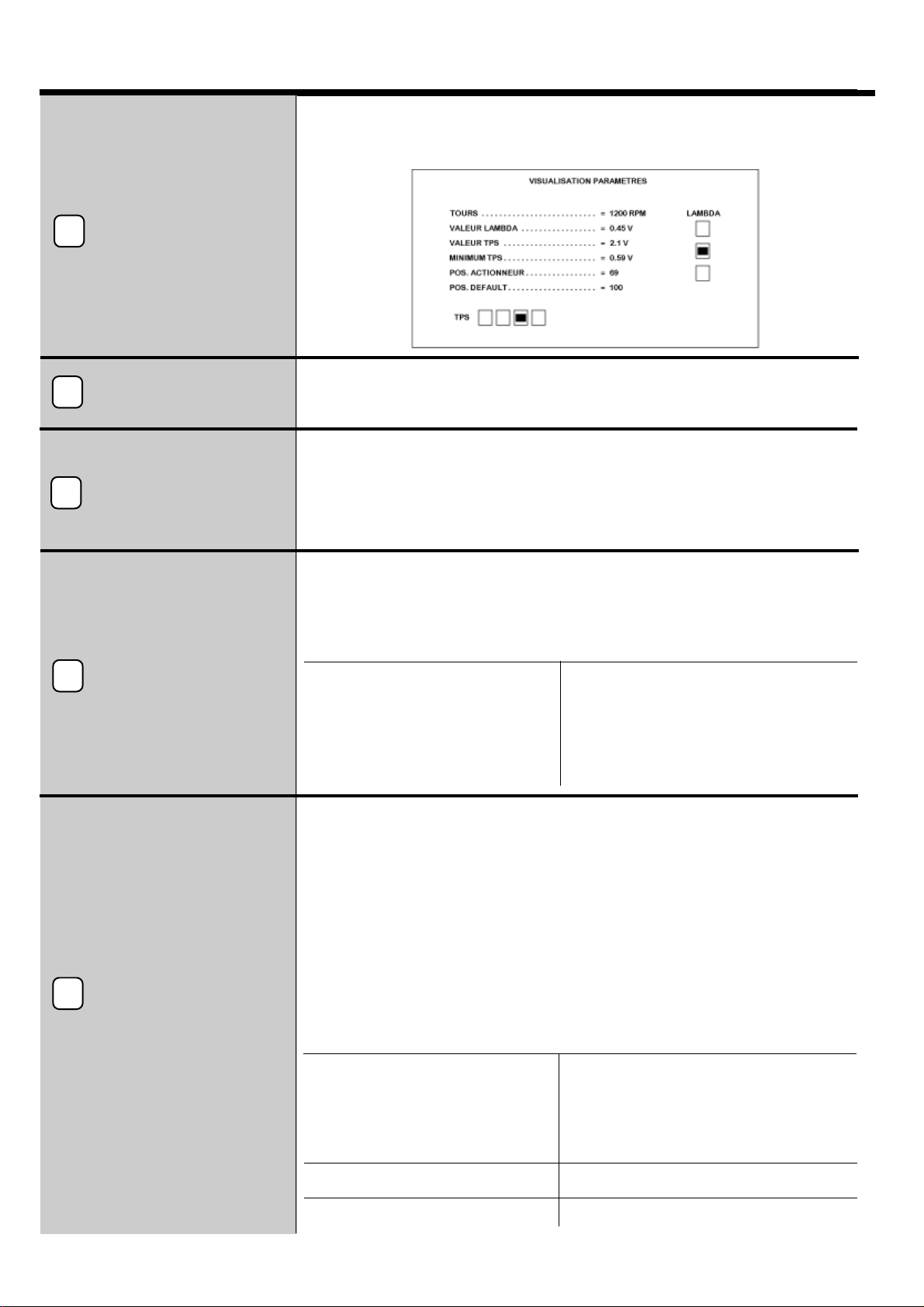
En installant le software spécial sur un ordinateur il est possible de se connecter à
travers l’interface sériale à la centrale du “VOILA PLUS” pour modifier les différents
paramètres et en visualiser le fonctionnement.
2
Testeur visualisation
paramètres
Programmation et
visualisation
paramètres
1
Commutateur
3
Avec le Testeur il est possible de visualiser:
- position moteur pas-à-pas à travers le display à 3 chiffres
- fonctionnement sonde lambda.
(
TPS)
Senseur position
accélérateur
5
Moteur
pas-à-pas
4
Le commutateur n’est pas fourni dans la confection du “VOILA PLUS”, IL DOIT
ETRE ACHETE A PART
La liaison au fil BLEU du commutateur (sortie services GAZ) est nécessaire pour
utiliser le “VOILA PLUS” seulement pendant le fonctionnement à GAZ. Durant le
fonctionnement à ESSENCE, toutes les liaisons d’origine seront rétablies.
Table of contents
Languages:
Popular Control Unit manuals by other brands

EP Solar
EP Solar Tracer1215BN instruction manual

Paradox
Paradox MG-RCV3 Reference and installation manual

Kieback&Peter
Kieback&Peter RBW322-FTL-902 operating instructions

FiveCo
FiveCo FMod-IPAXESCTRL user manual

GOAL ZERO
GOAL ZERO Yeti Link user guide

MetaSystem
MetaSystem Wi 3.0 installation instructions


DSEGenset
DSEGenset DSE8661 Operator's manual

Ublox
Ublox C94-M8P user guide

Blue Technix
Blue Technix ADEV-BF52xC V1.1 Hardware user manual

Spraying Systems
Spraying Systems TeeJet Technologies AEROS 9040 User Settings Manual

SPX FLOW
SPX FLOW APV DELTA SVS1F DN25-100 instruction manual

Paradox
Paradox IP150+ installation manual