Blue Technix ADEV-BF52xC V1.1 Instructions for use

Hardware User Manual
ADEV-BF52xC V1.1

ADEV-BF52xC_HUM_V1.1.docx 2
Contact
Bluetechnix Mechatronische Systeme GmbH
Waidhausenstraße 3/19
A-1140 Vienna
AUSTRIA/EUROPE
office@bluetechnix.at
http://www.bluetechnix.com
Document No.: 100-8232-1-1.3
Date: 2011-05-30

ADEV-BF52xC_HUM_V1.1.docx 3
Table of Contents
Blackfin®Core Modules............................................................................................................................................................................6
Blackfin®Development Boards .............................................................................................................................................................8
1Introduction .......................................................................................................................................................................................9
1.1 Overview....................................................................................................................................................................................9
1.2 Key Features .............................................................................................................................................................................9
1.3 Applications............................................................................................................................................................................10
2General Description ......................................................................................................................................................................11
2.1 Functional Description.......................................................................................................................................................11
2.1.1 Powering........................................................................................................................................................................11
2.1.2 USB Device ....................................................................................................................................................................11
2.1.3 Analog Interface..........................................................................................................................................................11
2.1.4 Digital Interface...........................................................................................................................................................12
2.2 PCB Placement ......................................................................................................................................................................13
2.3 Switches, Jumpers and LEDs............................................................................................................................................13
2.3.1 Power Source Selection Jumper...........................................................................................................................13
2.3.2 Power LED .....................................................................................................................................................................13
2.3.3 GPIO LEDs......................................................................................................................................................................13
2.3.4 GPIO Button..................................................................................................................................................................14
2.3.5 Reset Button .................................................................................................................................................................14
2.3.6 DIP-Switch .....................................................................................................................................................................14
2.4 Mechanical Outline..............................................................................................................................................................15
2.5 Electrical Specifications......................................................................................................................................................15
2.5.1 Operating Conditions ...............................................................................................................................................15
2.5.2 Maximum Ratings.......................................................................................................................................................16
2.5.3 ESD Sensitivity .............................................................................................................................................................16
3Support ..............................................................................................................................................................................................17
3.1 General Support....................................................................................................................................................................17
3.2 Board Support Packages ...................................................................................................................................................17
3.3 Blackfin® Software Support ..............................................................................................................................................17
3.3.1 BLACKSheep® OS ........................................................................................................................................................17
3.3.2 LabVIEW .........................................................................................................................................................................17
3.3.3 uClinux............................................................................................................................................................................17
3.4 Blackfin®Design Services...................................................................................................................................................17
3.4.1 Upcoming Products and Software Releases....................................................................................................17
4Ordering Information ...................................................................................................................................................................18
4.1 Predefined mounting options for ADEV-BF52xC.....................................................................................................18

ADEV-BF52xC_HUM_V1.1.docx 4
5Dependability..................................................................................................................................................................................19
5.1 MTBF..........................................................................................................................................................................................19
6Product History ...............................................................................................................................................................................20
6.1 Version Information.............................................................................................................................................................20
6.2 Anomalies................................................................................................................................................................................20
7Document Revision History .......................................................................................................................................................21
8List of Abbreviations.....................................................................................................................................................................22
AList of Figures and Tables............................................................................................................................................................23

ADEV-BF52xC_HUM_V1.1.docx 5
© Bluetechnix Mechatronische Systeme GmbH 2011
All Rights Reserved.
The information herein is given to describe certain components and shall not be considered as a guarantee of
characteristics.
Terms of delivery and rights of technical change reserved.
We hereby disclaim any warranties, including but not limited to warranties of non-infringement, regarding circuits,
descriptions and charts stated herein.
Bluetechnix makes and you receive no warranties or conditions, express, implied, statutory or in any
communication with you. Bluetechnix specifically disclaims any implied warranty of merchantability or fitness for a
particular purpose.
Bluetechnix takes no liability for any damages and errors causing of the usage of this board. The user of this board is
responsible by himself for the functionality of his application. He is allowed to use the board only if he has the
qualification. More information is found in the General Terms and Conditions (AGB).
Information
For further information on technology, delivery terms and conditions and prices please contact Bluetechnix
(http://www.bluetechnix.com).
Warning
Due to technical requirements components may contain dangerous substances.

ADEV-BF52xC_HUM_V1.1.docx 6
Blackfin®Core Modules
TCM-BF518-C-C-Q25S32F2 (TCM-BF518)
The Tiny Core Module TCM-BF518 is powered by Analog Devices' single core ADSP-BF518 processor; up to
400MHz, 32MB SDRAM, up to 8MB flash. The 2x60 pin expansion connectors are backwards compatible with
other Core Modules.
ACM-BF525C-C-C-Q25S64F4N1024
The Core Module ACM-BF525C is optimized for audio applications and performance. It is based on the high
performance ADSPBF525Cfrom Analog Devices. It addresses 64MByte SDRAM via its 16bit wide SDRAM bus, has
an onboard NOR-flash of 4MByte and a NAND-flash with 1024MByte.
CM-BF527-C-C-Q50S32F8 (CM-BF527)
The Core Module CM-BF527 is powered by Analog Devices' single core ADSP-BF527 processor; key features are
USB OTG 2.0 and Ethernet. The 2x60 pin expansion connectors are backwards compatible with other Core
Modules.
CM-BF533-C-C-Q25S32F2 (CM-BF533)
The Core Module CM-BF533 is powered by Analog Devices' single core ADSP-BF533 processor; up to 600MHz,
32MB SDRAM, 2MB flash, 2x60 pin expansion connectors at a size of 36.5x31.5mm.
TCM-BF537-C-I-Q25S32F8 (TCM-BF537)
The Tiny Core Module TCM-BF537 is powered by Analog Devices' single core ADSP-BF537 processor; up to
500MHz, 32MB SDRAM, 8MB flash, a size of 28x28mm, 2x60 pin expansion connectors, Ball Grid Array or Border
Pads for reflow soldering, industrial temperature range -40°C to +85°C.
CM-BF537-C-C-Q25S32F4 (CM-BF537E)
The Core Module CM-BF537 is powered by Analog Devices' single core ADSP-BF537 processor; up to 600MHz,
32MB SDRAM, 4MB flash, integrated TP10/100 Ethernet physical transceiver, 2x60 pin expansion connectors at a
size of 36.5x31.5mm.
CM-BF537-C-C-Q30S32F4-U (CM-BF537U)
The Core Module CM-BF537 is powered by Analog Devices' single core ADSP-BF537 processor; up to 600MHz,
32MB SDRAM, 4MB flash, integrated USB 2.0 Device, 2x60 pin expansion connectors at a size of 36.5x31.5mm.
CM-BF548-C-C-Q25S64F8 (CM-BF548)
The Core Module CM-BF548 is characterized by its numerous peripheral interfaces, its performance in
combination with its high speed memory interface (DDR). Key features are 533MHz, 64MB DDR SD-RAM
(266MHz), and 8MB flash.
CM-BF561-C-C-Q25S64F8 (CM-BF561)
The Core Module CM-BF561 is powered by Analog Devices' dual core ADSP-BF561 processor; up to 2x 600MHz,
64MB SDRAM, 8MB flash, 2x60 pin expansion connectors at a size of 36.5x31.5mm.
eCM-BF561-C-C-Q25S128F32 (eCM-BF561)
The Core Module CM-BF561 is powered by Analog Devices' dual core ADSP-BF561 processor; up to 2x 600MHz,
128MB SDRAM, 8MB flash, 2x100 pin expansion connectors and a size of 44x33mm.

ADEV-BF52xC_HUM_V1.1.docx 7
Core Module naming information
The idea is to put more Core Module specific technical information into the product name. New Core Module names
will have following technical information covered in their names.
•Product Family,
•CPU-Type,
•Connection-Type,
•Operating Temperature Range,
•Crystal Frequency [MHz],
•RAM [MB],
•Flash [MB],
•External Controllers
•
oSpecial and/or
Optional
oFormer name
That expands of course the name but allows the customer to get the most important Core Module specific
information at the first sight. Have a look at the example below to get an idea of the new Core Module names.
Example CM-BF537-C-C-Q25S32F4 (CM-BF537E)
- - - - - -
Product Family Former name
CM = Core Modul e Special
SBC = Single Board Computer Custom Core Modules or specials
CPU-Type uC = uclinux
Equals the name of CPU Extra controllers mounted
Connection-Type E = Ethernet
A = BGA U = USB
B = Border pa d Flash [MB]
C = Connector F = NOR Flash [MB]
S = S
Spec i al N = NAND Fl a sh [MB]
Operating Temperature Range RAM
A = Automoti ve (-40° to +125°) S = SDRAM [MB]
C = Commer ci a l (0° to +70°)
I = Industry (-40° to +85°)
Crystal Frequency
Notati on: QXX[MHz]
F4
(CM-BF537E)
S32
CM
BF537
C
C
Q25

ADEV-BF52xC_HUM_V1.1.docx 8
Blackfin®Development Boards
ADEV-BF52xC
Feature rich, low cost embedded audio development platform which supports Audio Core Modules (ACM). The
form factor of the ADEV-BF52xC allows easy integration of the board into OEM products. Dedicated interfaces such
as USB2.0, Line In/Out, headphone out and an onboard silicon microphone turn the ADEV-BF52xC into a full-
featured development platform for most embedded audio applications in commercial areas.
DEV-BF5xxDA-Lite
Get ready to program and debug Bluetechnix Core Modules with this tiny development platform including an USB-
Based Debug Agent. The DEV-BF5xxDA-Lite is a low cost starter development system including a VDSP++
Evaluation Software License.
DEV-BF548-Lite
Low-cost development board with a socket for Bluetechnix’ CM-BF548 Core Module. Additional interfaces are
available, e.g. an SD-Card, USB and Ethernet.
DEV-BF548DA-Lite
Get ready to program and debug Bluetechnix CM-BF548 Core Module with this tiny development platform
including an USB-Based Debug Agent. The DEV-BF548DA-Lite is a low-cost starter development system including a
VDSP++ Evaluation Software License.
eDEV-BF5xx
Feature rich, low cost rapid development platform which provides all interfaces on dedicated connectors and has all
Core Module pins routed to solder pads which easily can be accessed by the developers. The eDEV-BF5xx supports
the latest debugging interface from Analog Devices - ADI-SADA (Analog Devices Stand Alone Debug Agent).
EVAL-BF5xx
Tiny, low cost embedded platform which supports Bluetechnix powerful Blackfin® based Core Modules. The form
factor (75x75mm) of the EVAL-BF5xx allows easy integration of the board into OEM products. Dedicated interfaces
such as USB2.0, SD-card slot, CAN interface connectors and of course Ethernet, turn the EVAL-BF5xx into a full-
featured evaluation platform for most embedded applications.
Extender boards
Extender boards (EXT-BF5xx) are expanding the development and evaluation boards by several interfaces and
functionalities. Targeted application areas are: audio/video processing, security and surveillance, Ethernet access,
positioning, automation and control, experimental development and measuring.
Note! Bluetechnix is offering tailored board developments as well.

ADEV-BF52xC_HUM_V1.1.docx 9
1Introduction
The ADEV-BF52xC Development Board is a feature rich, low cost embedded audio development platform which
supports Bluetechnix latest powerful Blackfin® based Audio Core Modules like the ACM-BF525C. Based on
Bluetechnix’ long experience in industrial and commercial embedded systems design this kit is suited to the market
requirements to decrease time-to-market of your embedded audio applications.
The form factor of the ADEV-BF52xC allows easy integration of the board into OEM products. Dedicated interfaces
such as USB2.0, Line In/Out, headphone out and an onboard silicon microphone turn the ADEV-BF52xC into a full-
featured development platform for most embedded audio applications in commercial areas.
1.1 Overview
Solder Contacts
DC-Plug ACM-BF52xC
On-Board
Microphone
ADEV-BF52xC
UART/USB
Bridge
Power Supply
miniUSB-B
USB-B
Stereo Line In
Stereo Line Out
Mic
Headphone Out
4 x LED
4 x Push Button
Figure 1-1: Block diagram
1.2 Key Features
•Mini USB-B connector
•USB-B connector routed to the UART-USB bridge
•4 LEDs (red, green, yellow, orange)
•4 push-buttons
•Analog Audio Interface with microphone input, stereo line in and out, stereo headphone output
•On-board microphone
•USB-powered or wide range external DC supply (4.5 to 17V)
•Solder contacts for every digital IO-pin

ADEV-BF52xC_HUM_V1.1.docx 10
1.3 Applications
•Audio processing
•Speech recognition
•Synthesized voice
•Translation
•Voice control
•Talking toys

ADEV-BF52xC_HUM_V1.1.docx 11
2General Description
The ADEV-BF52xC has been designed as evaluation and development platform for both, Audio Core Modules ACM-
BF52xC or Speech Processing Modules e.g. SPM-B1xx. For more information about the modules refer the
Hardware User Manuals on our website.
2.1 Functional Description
2.1.1 Powering
The Step-Down DC-DC converter allows powering the development board via the DC-power plug, by connecting an
external power source between 4.5V and 17V.
Alternatively the board can be powered via either the USB-B or the mini USB-B connector. If so, the DC-DC converter
is not used.
To choose the correct powering configuration, the right jumper-setting is needed (see Table 2-3).
2.1.2 USB Device
The ADSP-BF52xC has an integrated USBOTG controller. The USB-D+ and USB-D- Lines can be routed directly to a
USB connector. The USB-ID Pin is used to indicate whether the SPM/ACM-BF52x is a USB-Device or a USB-Host. The
VUSB pin is used to indicate, if a USB bus power is applied.
The USB data lines and the VBUS are protected against ESD complying with IEC61000-4-2 level 4 standard:
•15kV air discharge
•8kV contact discharge
The ADEV-BF52xC uses only a mini USB-B connector and does not support USBOTG (host-mode).
2.1.3 Analog Interface
All analog I/Os are connected to 35mm stereo audio jacks. The stereo line-out is routed to the black jack, the stereo
headphone, the stereo line-in and the microphone lines are available on the standard-colored jacks.
Interface
Jack color
Function
Line In Blue Stereo audio input
Line Out Black Stereo audio output
Mic In Red Microphone input with phantom-power for electrets-microphones
HP out Green Stereo audio output capable for headphones
Table 2-1: Analog interface description
If no external microphone is plugged in to the red jack, the on-board microphone is active. To calibrate the gain
there is a small trimmer potentiometer which allows adjusting the built-in preamp.

ADEV-BF52xC_HUM_V1.1.docx 12
2.1.4 Digital Interface
All digital I/O signals are available on solder-pads. Some of them are routed to other parts (see Table 2-2 for detailed
interconnection information).
Signal Alt. Function Interface Connected to
PG13 UART1RX UART Routed to the UART-USB bridge
PG12 UART1TX UART Routed to the UART-USB bridge
PG2 SCLK SPI
PG3 MISO SPI
PG4 MOSI SPI
SDA I²C
SCL I²C
PG5 TMR1 GPIO DIP-switch S2 (usable for bootstrap implementations)
PG6 TMR2 GPIO DIP-switch S2 (usable for bootstrap implementations)
PG7 TMR3 GPIO push-button SW0
PG8 TMR4 GPIO red LED
PG9 TMR5 GPIO orange LED
PG10 TMR6 GPIO yellow LED
PG11 TMR7 GPIO green LED
PG14 GPIO push-button SW1
PF14 GPIO push-button SW2
PF15 GPIO push-button SW3
PF0 PPI.D0 GPIO
PF1 PPI.D1 GPIO
PF2 PPI.D2 GPIO
PF3 PPI.D3 GPIO
PF4 PPI.D4 GPIO
PF5
PPI.D5
GPIO
PF6 PPI.D6 GPIO
PF7 PPI.D7 GPIO
PPI.CLK1) PPI
PPI.FS1 PPI
Table 2-2: Digital interface description
1) Not available on connector version of the Core Module

ADEV-BF52xC_HUM_V1.1.docx 13
2.2 PCB Placement
DC-Plug Mini USB-B USB-B
RESET Button
red
orange
yellow
green
LEDs
Push-buttons
Configuration
Switch
Mic In
Line In
Headphone
Out
Line Out
Power source
selection
Power LED
ACM-BF52xC
connectors
On-board Mic
Figure 2-1: Board Layout
2.3 Switches, Jumpers and LEDs
The following section describes the Functionality of all jumpers switches and LEDs.
2.3.1 Power Source Selection Jumper
JP1 JP2, JP3 Power source Comment
short open Board powered via USB connectors Power source for Core Module is 5.0V
open short Board powered via DC-plug Power source for Core Module is 3.3V
Table 2-3: Power source selection
2.3.2 Power LED
The green power LED indicates that a power source is plugged into the board.
2.3.3 GPIO LEDs
Four LEDs are connected to GPIOs of the SPM. They can be free programmed by the developer.

ADEV-BF52xC_HUM_V1.1.docx 14
LED Color Blackfin GPIO
V10 Red PG8
V9 Orange PG9
V8 Yellow PG10
V7 Green PG11
Table 2-4: LED Description
2.3.4 GPIO Button
The four GPIO push-buttons are connected to Blackfin GPIOs of the SPM. They can be used to program a user
interaction. All buttons have a de-bouncing capacitor.
Button Blackfin GPIO
S3 PF15
S3 PF14
S5 PG14
S6 PG7
Table 2-5: Push-Button Description
2.3.5 Reset Button
The Reset button ties the SPM Reset to GND. Also the Reset button is de-bounced by hardware.
2.3.6 DIP-Switch
The DIP switch (S2) allows to disconnect the push-buttons from the GPIOs and to implement bootstrap
configurations.
Way Blackfin GPIO Function (ON State)
1 PG7 Connect to S6
2 PG14 Connect to S5
3 PF14 Connect to S4
4 PF15 Connect to S3
5 PG6 Tie PG6 to GND
6 PG5 Tie PG5 to GND
7 Not Connected -
8 Not Connected -
Table 2-6: DIP Switch Functionality

ADEV-BF52xC_HUM_V1.1.docx 15
2.4 Mechanical Outline
Figure 2-2: Board Outline Dimension
2.5 Electrical Specifications
2.5.1 Operating Conditions
Symbol Parameter Min Typical Max Unit
VINDC Input supply voltage on DC-plug 4.5 17 V
VINUSB Input supply voltage on USB connectors 4.5 5.0 5.5 V
I3V3 3.3V current 150 mA
VOH High level output voltage 2.4 V
VOL Low level output voltage 0.4 V
IIH IO input current 10 µA
IOZ Three state leakage current 10 µA
Table 2-7: Electrical Characteristics

ADEV-BF52xC_HUM_V1.1.docx 16
2.5.2 Maximum Ratings
Stressing the device above the rating listed in the absolute maximum ratings table may cause permanent damage
to the device. These are stress ratings only. Operation of the device at these or any other conditions greater than
those indicated in the operating sections of this specification is not implied. Exposure to absolute maximum rating
conditions for extended periods may affect device reliability.
Symbol Parameter Min Max Unit
VIO Input or output voltage -0.5 3.6 V
VIN Input supply voltage 3.0 5.5 V
IOH /IOL Current per pin 0 10 mA
TAMB Ambient temperature -40 85 °C
TSTO Storage temperature -55 150 °C
TSLD Solder temperature for 10 seconds 260 °C
φAMB Relative ambient humidity 90 %
Table 2-8: Absolute Maximum Ratings
2.5.3 ESD Sensitivity
ESD (electrostatic discharge) sensitive device. Charged devices and circuit boards can
discharge without detection. Although this product features patented or proprietary
protection circuitry, damage may occur on devices subjected to high energy ESD.
Therefore, proper ESD precautions should be taken to avoid performance degradation or
loss of functionality.

ADEV-BF52xC_HUM_V1.1.docx 17
3Support
3.1 General Support
General support for products can be found at Bluetechnix’ support site https://support.bluetechnix.at/wiki
3.2 Board Support Packages
Board support packages and software downloads are for registered customers
only https://support.bluetechnix.at/software/
3.3 Blackfin® Software Support
3.3.1 BLACKSheep® OS
BLACKSheep® OS stands for a powerfully and multithreaded real-time operating system (RTOS) originally designed
for digital signal processing application development on Analog Devices Blackfin® embedded processors. This high-
performance OS is based on the reliable and stable real-time VDK kernel from Analog Devices that comes with
VDSP++ IDE. Of course BLACKSheep® OS is fully supported by all Bluetechnix Core-Modules and development
hardware.
3.3.2 LabVIEW
You can get LabVIEW embedded support for Bluetechnix Core Modules by Schmid-Engineering
AG http://www.schmid-engineering.ch.
3.3.3 uClinux
You can get uClinux support (boot loader and uClinux) for Bluetechnix Core Modules at http://blackfin.uClinux.org.
3.4 Blackfin®Design Services
Based on more than seven years of experience with Blackfin, Bluetechnix offers development assistance as well as
custom design services and software development.
3.4.1 Upcoming Products and Software Releases
Keep up to date with all product changes, releases and software updates of Bluetechnix
at http://www.bluetechnix.com.

ADEV-BF52xC_HUM_V1.1.docx 18
4Ordering Information
4.1 Predefined mounting options for ADEV-BF52xC
Article Number Name Description
100-8232-1 ADEV-BF52xC ADEV-BF52xC Audio Development Board
100-3306 ADK - Audio Development Kit ADK - Audio Development Kit with ACM-
BF525C and ADEV-BF52xC
100-3307 Embedded Speech Processing Kit SPM-B101 Embedded Speech Processing Kit with ADEV-
BF52xC and SPM-B101
Table 4-1 - Ordering information
NOTE: Custom hard and software developments are available on request! Please contact Bluetechnix
(office@bluetechnix.com) if you are interested in custom hard- and software developments.

ADEV-BF52xC_HUM_V1.1.docx 19
5Dependability
5.1 MTBF
Please keep in mind that a part stress analysis would be the only way to obtain significant failure rate results,
because MTBF numbers just represent a statistical approximation of how long a set of devices should last before
failure. Nevertheless, we can calculate an MTBF of the development board using the bill of material. We take all the
components into account. The PCB and solder connections are excluded from this estimation. For test conditions
we assume an ambient temperature of 30°C of all development board components. We use the MTBF Calculator
from ALD (http://www.aldservice.com/) and use the reliability prediction MIL-217F2 Part Stress standard. Please get
in touch with Bluetechnix (office@bluetechnix.com) if you are interested in the MTBF result.

ADEV-BF52xC_HUM_V1.1.docx 20
6Product History
6.1 Version Information
Version Date Changes
1.1 2011-03-28 Bootstrap pin PG15 changed to PG5
LED order changed to green-yellow-orange-red
1.0 2010-12-21 First hardware release, thus no changes to report.
Table 6-1: Overview product changes
6.2 Anomalies
Version Date Description
1.1 2011 04 12 No anomalies reported yet.
1.0 2011 04 12 No anomalies reported yet.
Table 6-2: Overview product anomalies
Table of contents
Other Blue Technix Control Unit manuals
Blue Technix
Blue Technix TIM-UP-19k-S3-Spartan 6 User manual
Blue Technix
Blue Technix CM-BF527 Instructions for use
Blue Technix
Blue Technix Sentis ToF-P510 Instructions for use
Blue Technix
Blue Technix Sentis3D-M530 Instructions for use
Blue Technix
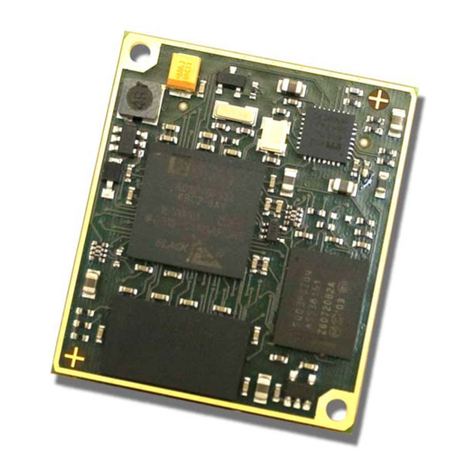
Blue Technix CM-BF537E Instructions for use
Blue Technix
Blue Technix Argos3D-P320 Instructions for use
Popular Control Unit manuals by other brands
Electronics Diversified
Electronics Diversified Omega 2 user manual
OPW
OPW 623V Installation and maintenance instructions

Sea Tel
Sea Tel DAC-2202 Installation and operation manual
Eaton
Eaton VICKERS DG3V-10 Series Overhaul manual
Baer
Baer M-Bus XC user manual

TECHCON SYSTEMS
TECHCON SYSTEMS TS924 Set up and operating instructions
