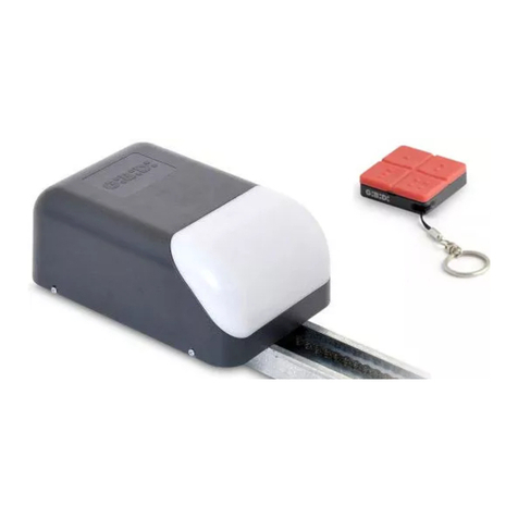
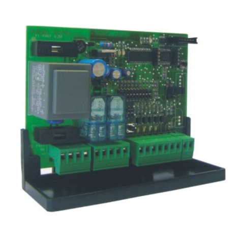
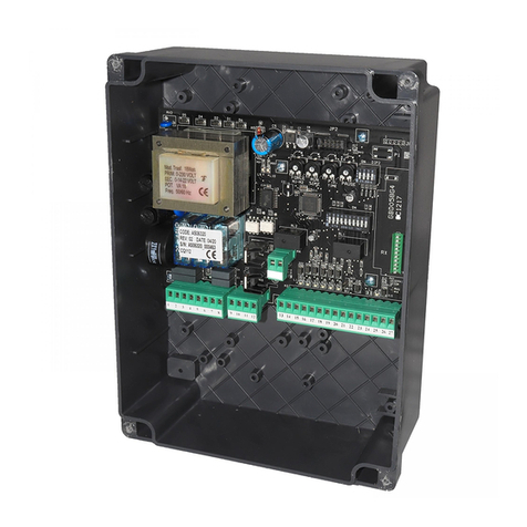
GiBiDi DSC90 User manual

In caso di guasto o anomalie di funzionamento staccare l’alimentazione a monte dell’apparecchiatura e
chiamare l’assistenza tecnica.
Le eventuali riparazioni devono essere eseguite da personale specializzato usando materiali originali e
certificati.
DSC 3
I
AVVERTENZE PER L’UTENTE
COLLEGAMENTI ELETTRICI: MORSETTIERE
• Usare conduttori con sezione minima 0,50 mm²
• Se per il medesimo ingresso della centrale ci sono più dispositivi con contatti di tipo NC, vanno posti in
serie tra loro.
• Non eseguire modifiche se non previste nelle presenti istruzioni. Il costruttore declina ogni
responsabilità ai fini del corretto funzionamento dell'automazione nel caso non vengano utilizzati i
componenti e gli accessori di propria produzione e idonei per l'applicazione prevista.
• La realizzazione di porte, cancelli automatici e garage è sottoposta alle seguenti norme vigenti:
- EN 12453 Porte e cancelli industriali, commerciali e da autorimessa.
- Sicurezza in uso di porte motorizzate – Requisiti
- EN 12978 Porte e cancelli industriali, commerciali e da garage. Dispostivi di sicurezza per porte e
cancelli motorizzate – Requisiti e metodi di prova.
• Questo manuale d’istruzioni si rivolge a persone abilitate all’installazione di “apparecchi sotto tensione”
pertanto si richiede una buona conoscenza della tecnica, esercitata come professione e nel rispetto
delle norme vigenti.
• La manutenzione deve essere eseguita da personale qualificato.
• Prima di eseguire qualsiasi operazione di pulizia o di manutenzione , scollegare l’apparecchiatura dalle
rete di alimentazione elettrica.
• L’ utilizzo dei prodotti e la loro destinazione ad usi diversi da quelli previsti, non è stata sperimentata dal
costruttore, pertanto i lavori eseguiti sono sotto la completa responsabilità dell’installatore.
• Entrambi gli ingressi devono connettersi ad un dispositivo sensibile 8k2, nel caso in cui fosse
necessario collegare un solo dispositivo sensibile bisognerà collegare all’ingresso non utilizzato una
resistenza 8k2 (data in dotazione).
Il morsetto n˚ 2 è di fatto collegato ad una massa per tanto in caso di alimentazione
continua prestare attenzione alla polarità.
Morsetto
J1
Posizione
1
9
11
3
2
10
12
13
4
5
6
7
8
Segnale
12/24 V
TEST
SAF 1
NO_1
12/24 V
TEST
COM
SAF 2
CM 1
NC_1
NO_2
CM 2
NC_2
Descrizione
Alimentazione positiva (vedi dip 1)
Ingresso TEST (se non utilizzato ponticellare con l’ingresso N˚2)
Ingresso SAFETY 1 per dispositivo sensibile 8,2KΩ
Uscita con contatto NO ad intervento ritardato
Alimentazione negativa (vedi dip 1)
Ingresso TEST (se non utilizzato ponticellare con l’ingresso N˚1)
Comune ingresso SAFETY 1-2
Ingresso SAFETY 2 per dispositivo sensibile 8,2KΩ
Comune uscita ritardato
Uscita con contatto NC ad intervento ritardato
Uscita con contatto NO ad intervento immediato
Comune uscita immediato
Uscita con contatto NC ad intervento immediato
Questa condizione
si ha con la
DSC90 alimentata
e con i dispositivi
sensore
correttamente
collegati.

I
DSC
4
ESEMPIO DI COLLEGAMENTO CON CENTRALE PROVVISTA DI INGRESSO COSTA
E TEST SICUREZZE
ESEMPIO DI COLLEGAMENTO CON CENTRALE NON PROVVISTA DI INGRESSO COSTA
E SENZA TEST SICUREZZE
2
3
COM
SAF.DEV.
+ACCESS
COM
+SAFETY
SAFETY DEVICE 8K2
SAFETY DEVICE
8K2
LS1
040G0
LS2
D4 D6
S1
~ +12/24
~ -12/24
NO_1
COM1
NC_1
NO_2
COM2
NC_2
TEST
TEST
SAF. 1
SAF. 2
COM
J1
SAFETY DEVICE
8K2
SAFETY DEVICE
8K2
COM
START
+ACCESS
COM
STOP
LS1
040G0
LS2
D4 D6
S1
~ +12/24
~ -12/24
NO_1
COM1
NC_1
NO_2
COM2
NC_2
TEST
TEST
SAF. 1
SAF. 2
COM
J1

SAFETY
DEVICE
SAFETY
DEVICE
SAFETY
DEVICE
8K2
SAF.1/SAF.2
COM
NORMALE NORMALE
TEST
V
DSC 5
I
PROGRAMMAZIONE FUNZIONI (DIP SWITCH S1)
IMPOSTAZIONI DI DEFAULT
ESEMPIO DI COLLEGAMENTO IN SERIE DI 2 O PIÙ BORDI SENSIBILI (4)
INGRESSO TEST
DIAGNOSTICA
Dip Stato Funzione Descrizione
DIP 1
DIP 1
DIP 2
OFF
ON
OFF
Alimentazione DSC90 da 20 ÷ 28 Vac e da 20 ÷ 30 Vdc
da 12 ÷ 19 Vac e da 12 ÷ 19 Vdc
Alimentazione DSC90
NON IMPLEMENTATO
DIP 1 E DIP 2 entrambi OFF
L’apparecchiatura consente di utilizzare la funzione TEST delle SICUREZZE disponibile in alcune centrali
per automazioni. La condizione si ha quando all’ingresso TEST è presente la tensione di alimentazione
mentre il test si ottiene togliendo la tensione all’ingresso per un tempo limitato durante il quale verrà
controllata la corretta commutazione del contatto di uscita.
Sulla DSC90 sono assemblati 2 led che indicano lo stato dei relè. Led rosso collegato all’uscita immediata
LED giallo collegato all’uscita ritardata.
Nel normale funzionamento risultano accesi. Quando si spengono indicano che si è verificata un’anomalia e
cioè l’intervento del dispositivo sensibile o l’errato funzionamento dello stesso. Pertanto quando i led
risulteranno accesi saranno attive le uscite corrispondenti; mentre quando risulteranno spenti le uscite
saranno disattive. Se collegata a centrali a bassa tensione Gi.Bi.Di. potrebbe verificarsi che il TEST della
scheda non sia presente con porta a riposo (chiusa); verificare che la stessa venga correttamente alimentata
ad inizio ciclo.
4
5

I
DSC
6
COLLAUDO
MANUTENZIONE
SMALTIMENTO DSC90
Di seguito sono indicate le fasi più importanti del collaudo che dovrà essere eseguito da personale qualificato
nel pieno rispetto delle leggi e delle normative vigenti:
• Verificare quanto scritto nelle avvertenze dell’installazione
• Verificare il valore di resistenza del dispositivo sensibile (8K2± 10%)
• Collegare il dispositivo sensibile e verificare l’accensione dei due led giallo e rosso.
• Attivare il dispositivo sensibile e verificare che immediatamente il led rosso si spenga e dopo 2 secondi si
spenga anche il led giallo.
• Disattivare il dispositivo sensibile e verificare che i due led si accendano immediatamente.
• Se viene utilizzato l’ingresso TEST verificare che la centrale a cui è collegato esegua correttamente la
procedura.
Gi.Bi.Di. consiglia una manutenzione regolare ogni 12 mesi effettuata da personale qualificato nel rispetto
della sicurezza e secondo quanto previsto dalle normative vigenti.
Gi.Bi.Di consiglia di riciclare i componenti in plastica e di smaltire in appositi centri abilitati i
componenti elettronici evitando perciò di contaminare l’ambiente con sostanze inquinanti.
DICHIARAZIONE DI CONFORMITÀ CE
Firma Ammistratore Delegato
Oliviero Arosio
Il fabbricante:
GI.BI.DI. S.r.l.
Via Abetone Brennero, 177/B,
46025 Poggio Rusco (MN) ITALY
Dichiara che i prodotti:
DSC90
Sono conformi alle seguenti Direttive CEE:
• Direttiva EMC 2004/108/CE e successive modifiche
e che sono state applicate le seguenti norme:
•EN61000-6-2, EN61000-6-3
Data 14/12/09
APPARECCHIATURA ELETTRONICA

DSC 7
UK
Control unit
Power supply
TEST input voltage
Sensing device cable length
Operating temperature
Delayed output response time
Degree of protection
Sensing device (resistor) input value
Relay contacts
Type
DSC90 / AS05090
Dip Switch SW1
As power supply
Up to 40m (check 8K2 resistive value)
-20°C ÷ +60°C
2s±25%
IP55
8K2 Ω±10%
Max 0.5A
Max 48Vac
Device detection board with constant resistance
sensor 8K2 to be used for automatic doors,
gates and garage doors
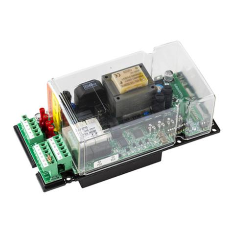
DSC90 is a detection board that allows constructing protection control units with sensing devices
characterised by a constant resistance of 8K2Ω used as safety devices with reference to EN 954-1. It has 2
separate relay outputs whose condition is linked to the status of the safety device. The control unit alone
is not a safety device but only a part thereof.
The control unit has two independent relays: LS1 with delayed action of about 2 seconds. LS2 with
instantaneous action.
When DCS90 is connected to control units with frame input (SAFETY/SAF.DEV.), connect the immediate
output (LS2) to the frame input (2). For control units without frame input the immediate output of the board
can be connected to the START input of the control unit (only if STEP-BY-STEP logic is set) in order to
obtain timely inversion of the gate/door motion; the delayed output (LS1) could be connected to the STOP
input to stop and block any gate movement two seconds after motion inversion (3).The TEST input is to be
used in control units equipped with the SAFETY DEVICE TEST function, which allows simulating a DCS90
board operation to test proper functioning.
• Before proceeding with installation, check that no voltage arrives at the system; if a buffer battery is
present, it must be disconnected.
• Make the connections referring to the following tables and to the attached screen-print. Incorrect
installation or improper use of the product may compromise system safety.
• Keep all the materials contained in the packaging away from children, since they pose a potential risk.
• Use conductors with a minimum cross-section of 0,50 mm²
PRODUCT DESCRIPTION
OPERATION
INSTALLATION WARNINGS

UK
DSC
8
In the event of an operating fault or failure, cut the power upstream of the control unit and call Technical
Service.
Any repairs must be carried out by specialised personnel using original and certified materials.
WARNINGS FOR THE USER
ELECTRICAL CONNECTIONS: TERMINAL BOARDS
• If there are several devices with N.C. contacts for the same control unit input, they should be connected
in series.
• Do not make modifications unless provided for in these instructions. The manufacturer declines all
responsibility for improper functioning of the automated device if the original components and
accessories suitable for the specific application are not used.
• The construction of automatic doors, gates and garage doors is subject to the following regulations:
EN 12453 Industrial and commercial doors, gates and garage doors.
Safety in use of motorized doors - Requirements
EN 12978 Industrial and commercial doors, gates and garage doors. Safety devices for motorized doors
and gates - Requirements and test methods.
• This instruction manual addresses persons qualified for installation of "live equipment". Therefore, good
technical knowledge and professional practice in compliance with the regulations in force are required.
• Maintenance must be carried out by qualified personnel.
• Before carrying out any cleaning or maintenance operation, disconnect the control unit from the mains.
• Use of the product for purposes different from the intended use has not been tested by the manufacturer,
therefore any work is carried out on full responsibility of the installer.
• Both inputs must be connected to a 8k2 sensing device; if only one sensing device needs to be
connected, connect an 8k2 resistor (provided) to the unused input.
Terminal n˚2 is connected to a ground, therefore, in case of direct current pay attention
to the polarity.
J1
1
9
11
3
2
10
12
13
4
5
6
7
8
12/24 V
TEST
SAF 1
NO_1
12/24 V
TEST
COM
SAF 2
CM 1
NC_1
NO_2
CM 2
NC_2
Positive power supply (see dip switch 1)
TEST input (if not used, jumper with input 2˚)
SAFETY 1 input for 8.2KΩ sensing device
Delayed output with N.O. contact
Negative power supply (see dip switch 1)
TEST input (if not used, jumper with input 1˚)
SAFETY 1-2 input common
SAFETY 2 input for 8.2KΩ sensing device
Delayed output common
Delayed output with N.C. contact
Immediate output with N.O. contact
Immediate output common
Immediate output with N.C. contact
This condition is
obtained with
DSC90 powered
and with the
sensing devices
properly connected.
Terminal Position Signal Description

DSC 9
UK
EXAMPLE OF CONNECTION WITH CONTROL UNIT WITHOUT FRAME INPUT WITH SAFETY TEST
CONNECTION EXAMPLE FOR CONTROL UNIT WITHOUT FRAME INPUT AND WITHOUT
SAFETY TEST
2
3
COM
SAF.DEV.
+ACCESS
COM
+SAFETY
SAFETY DEVICE 8K2
SAFETY DEVICE
8K2
LS1
040G0
LS2
D4 D6
S1
~ +12/24
~ -12/24
NO_1
COM1
NC_1
NO_2
COM2
NC_2
TEST
TEST
SAF. 1
SAF. 2
COM
J1
SAFETY DEVICE
8K2
SAFETY DEVICE
8K2
COM
START
+ACCESS
COM
STOP
LS1
040G0
LS2
D4 D6
S1
~ +12/24
~ -12/24
NO_1
COM1
NC_1
NO_2
COM2
NC_2
TEST
TEST
SAF. 1
SAF. 2
COM
J1

UK
DSC
10
SAFETY
DEVICE
SAFETY
DEVICE
SAFETY
DEVICE
8K2
SAF.1/SAF.2
COM
NORMAL NORMAL
TEST
V
FUNCTION PROGRAMMING (DIP SWITCH S1)
DEFAULT SETTINGS
EXAMPLE OF SERIES CONNECTION OF TWO OR MORE CONDUCTIVE EDGES
TEST INPUT
DIAGNOSTICS
Dip Status Function Description
DIP 1
DIP 1
DIP 2
OFF
ON
OFF
Power supply DSC90 20-28 Vac and 20-30 Vdc
12-19 Vac and 12-19 Vdc
Power supply DSC90
NOT IMPLEMENTED
DIP 1 AND DIP 2 both OFF
The control unit allows using the SAFETY DEVICE TEST function available in some automated device
control units. Standard conditions are obtained when power is supplied to the TEST input, while the test
function is obtained by cutting the power to the input for a limited time during which correct switchover of
the output contact will be tested.
DSC70 is fitted with two LEDs which indicate the relay status. The red LED is connected to the immediate
output, the yellow LED to the delayed output.
During normal operation, these LEDs are on. When they go off it means that a fault has occurred i.e. the
sensing device has intervened or it is not functioning properly. Therefore, when the LEDs are on, the
corresponding outputs will be active, while when they are off, the outputs will be inactive.
If connected to Gi.Bi.Di. low-voltage control units, the board TEST function may not be available and the
port will be inactive (closed); check that it is properly powered at the beginning of the cycle.
5
4

DSC 11
UK
FINAL CHECK
MAINTENANCE
DSC90 DISPOSAL
The most important test phases are described below and must be carried out by qualified personnel in full
compliance with the current laws and regulations:
• Read the instructions given under installation warnings
• Check the resistance value of the sensing device (8K2± 10%)
• Connect the sensing device and check that the yellow LED and the red LED come on.
• Activate the sensing device and check that the red LED immediately goes off and the yellow LED after 2
seconds.
• Deactivate the sensing device and check that the two LEDs immediately come on.
• If the TEST input is used, check that the control unit to which it is connected properly runs the procedure.
Gi.Bi.Di. recommends regular maintenance every 12 months by qualified personnel in order to assure
safety according to current regulations.
Gi.Bi.Di advises recycling the plastic components and to dispose of them at special
authorised centres for electronic components thus protecting the environment from
polluting substances.
The manufacturer:
GI.BI.DI. S.r.l.
Via Abetone Brennero, 177/B,
46025 Poggio Rusco (MN) ITALY
Declares that the products:
DSC90
Are in conformity with the following CEE Directives:
• EMC Directive 2004/108/CE and subsequent amendments
and that the following standards have been applied:
• EN61000-6-2, EN61000-6-3
Date 14/12/09
ELECTRONIC CONTROL UNIT
CE DECLARATION OF CONFORMITY
Managing Director
Oliviero Arosio

F
DSC
12
DSC70 est une carte de détection qui permet de réaliser des appareils de protection avec des dispositifs
senseurs à résistance constante 8K2 Ω utilisés comme dispositifs de sécurité selon la norme EN 954-1.
Prévoit 2 sorties séparées à relais, dont la condition est liée à la condition du dispositif de sécurité.
L'appareil seul n'est pas un dispositif de sécurité, mais uniquement une partie de ce dernier.
Sur l'appareil, il y a deux relais indépendants: LS1 avec intervention retardée d'environ 2 secondes. Le
relais LS2 avec intervention instantanée.
Lorsque DCS90 est connectée à des unités équipées d'une entrée membrure (SAFETY/SAF.DEV.), il
suffit de connecter la sortie immédiate (LS2) à l'entrée membrure (2). Pour les unités de contrôles
équipées de l'entrée membrure, il est possible de connecter à la sortie immédiate de la carte l'entrée
START de l'unité (uniquement si paramétrée sur logique PAS-PAS) pour pouvoir obtenir une inversion
immédiate du mouvement de la porte ; la sortie retardée (LS1) peut être connectée à l'entrée STOP de
manière à arrêter et à bloquer tout mouvement de la porte deux secondes après l'inversion du mouvement
(3). L'entrée TEST doit être utilisée dans les unités qui prévoient la fonction du TEST des dispositifs de
SECURITE, permettant de simuler une intervention de la carte DCS90 pour contrôler le bon
fonctionnement de cette dernière.
• Avant l'installation, il faut contrôler que l'installation n'est pas sous tension; et s'il y a une batterie à
tampon, il faut la déconnecter.
• Il faut effectuer les connexions en se référant aux tableaux suivants et à la sérigraphie jointe. Une
mauvaise installation ou une mauvaise utilisation du produit peut compromettre la sécurité de
l'installation.
• Tous les matériaux se trouvant dans l'emballage ne doivent pas être laissés à la portée des enfants, car
ils peuvent être dangereux.
• Utiliser des conducteurs ayant une section minimum de 0,50 mm²
Appareil
Alimentation
Tension d'entrée TEST
Longueur câble dispositif sensible
Température de service
Temps de réponse sortie retardée
Degré de protection
Valeur de l'entrée du dispositif sensible
(résistance)
Contacts relais
Type
DSC70 / AS05090
Dip Switch SW1
Comme l'alimentation
Jusqu'à 40m (contrôler la valeur résistive 8K2)
-20°C ÷ +60°C
2s±25%
IP55
8K2 Ω±10%
Max 0.5A
Max 48Vac
Carte de détection des dispositifs avec senseur à
résistance constante 8K2 Ω à utiliser dans les
automations de portes, de grilles et de portes de garage
DESCRIPTION DU PRODUIT
FONCTIONNEMENT DU PRODUIT
AVERTISSEMENTS POUR L'INSTALLATION

DSC 13
F
En cas de panne ou de dysfonctionnements, il faut couper l'alimentation en amont de l'appareil et appeler
le service d'assistance technique.
Les éventuelles réparations doivent être exécutées par un personnel spécialisé qui utilise des matériels
d'origine et certifiés.
AVERTISSEMENTS POUR L'UTILISATEUR
BRANCHEMENTS ELECTRIQUES: BORNIERS
• S'il y a plusieurs dispositifs à contacts type NF, pour la même entrée de l'unité, il faut les placer en série
entre eux.
• N'effectuer aucune modification n'étant pas prévue dans ces instructions. Le constructeur décline toute
responsabilité, quant au bon fonctionnement de l'automation, en cas d'utilisation de composants et
d'accessoires n'étant pas de sa production et inappropriés pour l'application prévue.
• La réalisation de portes, de grilles automatiques et de portes de garage, est soumise aux normes
suivantes en vigueur :
EN 12453 Portes et grilles industrielles, commerciales et de garage.
Sécurité pour portes motorisées - Conditions requises
EN 12978 Portes et grilles industrielles, commerciales et de garage. Dispositifs de sécurité pour portes
et grilles motorisées - Conditions requises et types d'essais.
• Ce Manuel d'instructions s'adresse aux personnes autorisées à effectuer la mise en place "d'appareils
sous tension". Il faut donc avoir une bonne connaissance de la technique, exercée comme profession et
conformément aux réglementations en vigueur.
• La maintenance doit être effectuée par un personnel qualifié.
• Avant d'effectuer toute opération de nettoyage ou de maintenance, il faut débrancher l'appareil des
réseaux d'alimentation électrique.
• L'utilisation des produits et leur destination à des usages différents de ceux prévus, n'a pas été
expérimentée par le constructeur, les travaux exécutés sont donc sous l'entière responsabilité de
l'installateur.
• Les deux entrées doivent se connecter à un dispositif sensible 8k2, s'il faut connecter un seul dispositif
sensible, il faudra connecter une résistance 8k2 (fournie en équipement) à l'entrée inutilisée.
La borne n˚2 est connectée à une masse, par conséquent, en cas d'alimentation
continue, il faut faire attention à la polarité.
J1
1
9
11
3
2
10
12
13
4
5
6
7
8
12/24 V
TEST
SAF 1
NO_1
12/24 V
TEST
COM
SAF 2
CM 1
NC_1
NO_2
CM 2
NC_2
Alimentation positive (voir Dip 1)
Entrée TEST (si inutilisée, raccorder à l'entrée N˚2)
Entrée SAFETY 1 pour dispositif sensible 8,2 KΩ
Sortie avec contact NO à intervention retardée
Alimentation négative (voir Dip 1)
Entrée TEST (si inutilisée, raccorder à l'entrée N˚1)
Commun entrée SAFETY 1-2
Entrée SAFETY 2 pour dispositif sensible 8,2 KΩ
Commun sortie retardée
Sortie avec contact NF à intervention retardée
Sortie avec contact NO à intervention immédiate
Commun sortie immédiate
Sortie avec contact NF à intervention immédiate
Cette condition
s'obtient avec la
DSC90 alimentée
et avec les
dispositifs senseur
correctement
connectés.
Borne Position Signal Description

F
DSC
14
EXEMPLE DE CONNEXION AVEC DES UNITES EQUIPEES D'ENTREE MEMBRURE
AVEC TEST DE SECURITE
EXEMPLE DE RACCORDEMENT AVEC CENTRALE DÉPOURVUE D'ENTRÉE MEMBRURE
ET SANS TEST DE SÉCURITÉ
2
3
COM
SAF.DEV.
+ACCESS
COM
+SAFETY
SAFETY DEVICE 8K2
SAFETY DEVICE
8K2
LS1
040G0
LS2
D4 D6
S1
~ +12/24
~ -12/24
NO_1
COM1
NC_1
NO_2
COM2
NC_2
TEST
TEST
SAF. 1
SAF. 2
COM
J1
SAFETY DEVICE
8K2
SAFETY DEVICE
8K2
COM
START
+ACCESS
COM
STOP
LS1
040G0
LS2
D4 D6
S1
~ +12/24
~ -12/24
NO_1
COM1
NC_1
NO_2
COM2
NC_2
TEST
TEST
SAF. 1
SAF. 2
COM
J1

DSC 15
F
SAFETY
DEVICE
SAFETY
DEVICE
SAFETY
DEVICE
8K2
SAF.1/SAF.2
COM
NORMAL NORMAL
TEST
V
PROGRAMMATION FONCTIONS (DIP SWITCH S1)
PARAMETRAGES PAR DÉFAUT
EXEMPLE DE RACCORDEMENT EN SERIE DE 2 OU DE PLUSIEURS BORDS SENSIBLES
ENTRÉE TEST
DIAGNOSTIC
Dip Condition Fonction Description
DIP 1
DIP 1
DIP 2
OFF
ON
OFF
Alimentation DSC90 de 20 ÷ 28 Vac et de 20 ÷ 30 Vdc
de 12 ÷ 19 Vac et de 12 ÷ 19 Vdc
Alimentation DSC90
NON- IMPLÉMENTÉ
DIP 1 ET DIP 2 tous les deux sur OFF.
L'appareil permet d'utiliser la fonction TEST des dispositifs de SÉCURITÉ disponible dans certaines
unités pour des automations. Les conditions standard s'obtiennent lorsque, à l'entrée du TEST, on a une
tension d'alimentation; par contre, le test s'obtient en coupant le courant à l'entrée pendant un temps
limité, durant lequel sera contrôlée la commutation exacte du contact de sortie.
Sur la DCS90, il y a deux témoins lumineux qui indiquent la condition des relais. Témoin rouge connecté à
la sortie immédiate TEMOIN jaune connecté à la sortie retardée.
Pendant le fonctionnement normal ces deux témoins sont allumés. Lorsqu'ils s'éteignent, ils signalent
qu'une anomalie s'est produite c'est-à-dire l'intervention du dispositif sensible ou le dysfonctionnement de
ce dernier. Par conséquent, lorsque les témoins lumineux sont allumés, les sorties correspondantes sont
activées ; par contre, quand ils sont éteints les sorties sont désactivées. Si elle est connectée à des unités
à basse tension Gi.Bi.Di., il possible que le TEST de la carte soit absent lorsque la porte est au repos
(fermée) ; contrôler que cette dernière est correctement alimentée au début du cycle.
4
5

F
DSC
16
ESSAI
MAINTENANCE
ELIMINATION DSC90
Vous trouverez ci-après les phases les plus importantes de l'essai qui devra être effectué par un personnel
qualifié conformément aux lois et réglementations en vigueur:
• Contrôler ce qui est indiqué dans les consignes pour l'installation
• Contrôler la valeur de résistance du dispositif sensible (8K2± 10%)
• Connecter le dispositif sensible, puis contrôler que les deux témoins lumineux jaune et rouge, s'allument
• Activer le dispositif sensible, puis contrôler que le témoin lumineux rouge s'éteint immédiatement et
qu'après 2 secondes le témoin jaune s'éteint à son tour.
• Désactiver le dispositif sensible, puis contrôler que les deux témoins lumineux s'allument immédiatement.
• Si l'on utilise l'entrée TEST, contrôler que l'unité à laquelle elle est connectée, effectue correctement la
procédure.
Gi.Bi.Di. conseille une maintenance régulière tous les 12 mois, effectuée par un personnel qualifié, en toute
sécurité et selon ce qui est prévu par les normes en vigueur.
Gi.Bi.Di conseille de recycler les composants en plastique et de remettre les composants
électroniques à des centres spécialisés pour éviter de polluer l'environnement avec des
substances polluantes.
La société:
GI.BI.DI. S.r.l.
Via Abetone Brennero, 177/B,
46025 Poggio Rusco (MN) ITALY
Déclare que les produits:
DSC90
Sont en conformité avec les exigences des Directives CEE:
• Directive EMC 2004/108/CE et ses modifications
et que les normes suivantes ont été appliquées:
• EN61000-6-2, EN61000-6-3
Date 14/12/09
APPAREIL ÉLECTRONIQUE
DÉCLARATION DE CONFORMITÉ CE
Signature Administrateur Délégué
Oliviero Arosio

DSC 17
F
DSC90 es una tarjeta de detección que permite realizar aparatos de protección con dispositivos sensores de
resistencia constante de 8K2 utilizados como dispositivos de seguridad conforme a la norma EN 954-1.
Prevé 2 salidas de relé independientes, cuya situación depende del estado del dispositivo de seguridad.
El equipo por sí solo no es dispositivo de seguridad, sino una parte del mismo.
Ω
El equipo tiene dos relés independientes: LS1 con intervención retrasada de unos 2 segundos. El relé LS2
con intervención instantánea.
Cuando DCS90 está conectada a centralitas provistas de entrada de banda de seguridad
(SAFETY/SAF.DEV.), basta conectar la salida inmediata (LS2) a la entrada de banda de seguridad (2). En
las centralitas de control desprovistas de la entrada de banda de seguridad, es posible conecta a la salida
inmediata de la tarjeta la entrada START de la centralita (sólo si se ha programado con una lógica PASO A
PASO) para poder obtener una inversión rápida del movimiento de la puerta; la salida retardada (LS1)
podría conectarse a la entrada STOP para detener e impedir cualquier movimiento de la puerta dos
segundos tras la inversión del movimiento (3). La entrada TEST se utiliza en las centralitas que prevén la
función de TEST de las SEGURIDADES, permitiendo simular una intervención de la tarjeta DCS90 para
verificar el funcionamiento correcto de la misma.
• Antes de proceder a la instalación debe comprobarse que no llegue tensión al sistema; y si hay una
batería de apoyo es necesario desconectarla.
• Realice las conexiones consultando las siguientes tablas y la serigrafía adjunta. La instalación o
utilización incorrecta del equipo puede afectar la seguridad del equipo.
• Todo material presente en el embalaje debe mantenerse fuera del alcance de los niños, ya que constituye
una posible fuente de peligro.
• Usar conductores con una sección mínima de 0,50 mm²
Equipo
Alimentación
Tensión de entrada TEST
Longitud de cable del dispositivo sensor
Temperatura de funcionamiento
Tiempo de respuesta de la salida retardada
Grado de protección
Valor de la entrada del dispositivo
sensible (resistencia)
Contactos de los relés
Tipo
DSC90 / AS05090
Dip Switch SW1
Como alimentación
hasta 40m (verifique el valor de resistencia 8K2)
-20°C ÷ +60°C
2s±25%
IP55
8K2 Ω±10%
Max 0.5A
Max 48Vac
Tarjeta de detección de dispositivos con sensor de
resistencia constante de 8K2 Ω para utilizarla en la
automatización de puertas, cancelas y garajes
DESCRIPCIÓN DEL PRODUCTO
FUNCIONAMIENTO DEL PRODUCTO
ADVERTENCIAS PARA LA INSTALACIÓN

E
DSC
18
En caso de averías o anomalías de funcionamiento, desconecte la alimentación aguas arriba del equipo y
llame al servicio de asistencia técnica.
Cualquier reparación debe ser realizada por personal especializado y usando materiales originales y
certificados.
ADVERTENCIAS PARA EL USUARIO
CONEXIONES ELÉCTRICAS: TABLEROS DE BORNES
• Si para una misma entrada de la central hay varios dispositivos con contactos de tipo NC, colocarlos en
serie.
• No realizar modificaciones que no estén previstas en estas instrucciones. El fabricante declina toda
responsabilidad sobre el funcionamiento correcto de la automatización si no se utilizan los
componentes y accesorios originales y adecuados para la aplicación prevista.
• La realización de puertas, cancelas automáticas y garajes esta sujeta a las normas vigentes siguientes:
EN 12453 Puertas industriales, comerciales, de garaje y portones.
Seguridad en uso de puertas motorizadas - Requisitos
EN 12978 Puertas industriales, comerciales, de garaje y portones. Dispositivos de seguridad para
puertas y cancelas motorizadas - Requisitos y métodos de prueba.
• Este manual de instrucciones está destinado a personas capacitadas para la instalación de "equipos
bajo tensión". Por lo tanto, se requiere un buen conocimiento técnico, ejercido como profesión y
respetando las normas vigentes.
• El mantenimiento debe ser realizado por personal capacitado.
• Antes de realizar cualquier operación de limpieza o mantenimiento, desconecte el equipo de la red de
alimentación eléctrica.
• El uso de los productos y su destinación a usos no previstos no han sido experimentados por el
fabricante, por lo que cualquier trabajo realizado queda bajo completa responsabilidad del instalador.
• Ambas entradas deben conectarse a un dispositivo sensor de 8k2. Si fuera necesario conectar un solo
dispositivo sensor deberá conectarse una resistencia de 8k2 (incluida en la entrega) a la entrada no
utilizada.
El borne n.˚ 2 está conectado efectivamente a una masa, por lo que en caso de
alimentación continua debe prestarse atención a la polaridad.
J1
1
9
11
3
2
10
12
13
4
5
6
7
8
12/24 V
TEST
SAF 1
NO_1
12/24 V
TEST
COM
SAF 2
CM 1
NC_1
NO_2
CM 2
NC_2
Alimentación positiva (véase dip 1)
Entrada TEST (si no se utiliza, conecte en puente con la entrada n°2)
Entrada SAFETY 1 para dispositivo sensor de 8,2 KΩ
Salida con contacto NA de actuación retardada
Alimentación negativa (véase dip 1)
Entrada TEST (si no se utiliza, conecte en puente con la entrada n°1)
Entrada común SAFETY 1-2
Entrada SAFETY 2 para dispositivo sensor de 8,2 KΩ
Salida retardada común
Salida con contacto NC de actuación retardada
Salida con contacto NA de actuación inmediata
Salida inmediata común
Salida con contacto NC de actuación inmediata
Esta condición
se produce con la
DSC90 alimentada y
con los dispositivos
sensores
correctamente
conectados.
Borne Posición Señal Descripción

DSC 19
E
EJEMPLO DE CONEXIÓN CON CENTRALITA DESPROVISTA DE ENTRADA DE BANDA DE
SEGURIDAD Y TEST DE SEGURIDAD
EJEMPLO DE CONEXIÓN CON CENTRAL NO PROVISTA DE ENTRADA DE BANDA
DE SEGURIDAD Y SIN TEST DE SEGURIDAD
2
3
COM
SAF.DEV.
+ACCESS
COM
+SAFETY
SAFETY DEVICE 8K2
SAFETY DEVICE
8K2
LS1
040G0
LS2
D4 D6
S1
~ +12/24
~ -12/24
NO_1
COM1
NC_1
NO_2
COM2
NC_2
TEST
TEST
SAF. 1
SAF. 2
COM
J1
SAFETY DEVICE
8K2
SAFETY DEVICE
8K2
COM
START
+ACCESS
COM
STOP
LS1
040G0
LS2
D4 D6
S1
~ +12/24
~ -12/24
NO_1
COM1
NC_1
NO_2
COM2
NC_2
TEST
TEST
SAF. 1
SAF. 2
COM
J1

E
DSC
20
SAFETY
DEVICE
SAFETY
DEVICE
SAFETY
DEVICE
8K2
SAF.1/SAF.2
COM
NORMAL NORMAL
TEST
V
PROGRAMACIÓN DE LAS FUNCIONES (DIP SWITCH S1)
CONFIGURACIÓN PREDETERMINADA
EJEMPLO DE CONEXIÓN EN SERIE DE DOS O MÁS BORDES SENSIBLES
ENTRADA TEST
DIAGNÓSTICO
Dip Estado Función Descripción
DIP 1
DIP 1
DIP 2
OFF
ON
OFF
Alimentación DSC90 de 20 ÷ 28 Vac y de 20 ÷ 30 Vdc
de 12 ÷ 19 Vac y de 12 ÷ 19 Vdc
Alimentación DSC90
NO IMPLEMENTADO
DIP 1 Y DIP 2 ambos en OFF
El equipo permite utilizar la función TEST de las SEGURIDADES disponible en algunas centralitas de
automatización. Las condiciones estándar se obtienen cuando en la entrada TEST existe la tensión de
alimentación y se realiza la prueba retirando la tensión de la entrada por un tiempo limitado durante el cual
se controlará la correcta conmutación del contacto de salida.
En DSC90 hay ensamblados dos leds que indican el estado de los relés. Led rojo conectado a la salida
inmediata LED amarillo conectado a la salida retardada.
Durante el funcionamiento normal, deben estar encendidos. Si se apagan indican que se ha producido
una anomalía, es decir la actuación del dispositivo sensor o un funcionamiento incorrecto del mismo. Por
tanto, si los led están encendidos están activas las salidas correspondientes mientras que si se apagan
las salidas están inactivas. Si está conectada a centrales de baja tensión de Gi.Bi.Di. podrá comprobarse
que el TEST de la placa no esté presente con la puerta en reposo (cerrada); verificar que la misma está
correctamente alimentada al inicio del ciclo.
4
5

DSC 21
E
PRUEBA
MANTENIMIENTO
ELIMINACIÓN DE LA DSC90
A continuación se indican las fases más importantes de la conexión que deberá realizarse por personal
cualificado para el pleno respeto de las leyes y las normativas vigentes:
• Verificar todo lo indicado en las advertencias de instalación
• Verificar el valor de la resistencia del dispositivo sensor (8K2± 10%)
• Conectar el dispositivo sensor y comprobar el encendido de los dos leds amarillo y rojo.
• Activar el dispositivo sensor y comprobar que el led rojo se apague inmediatamente y el led amarillo, 2
segundos después.
• Desactivar el dispositivo sensor y comprobar que ambos led se enciente inmediatamente.
• Si se utiliza la entrada TEST, compruebe que la centralita a la que está conectada efectúe
correctamente el procedimiento.
Gi.Bi.Di. aconseja un mantenimiento periódico cada doce meses, realizado por personal cualificado,
respetando la seguridad y conforme a todo lo previsto en las normativas vigentes.
Gi.Bi.Di aconseja reciclar los componentes de plástico y llevar los componentes
electrónicos a los centros de recogida correspondientes evitando de este modo la
contaminación ambiental con sustancias perjudiciales.
El fabricante:
GI.BI.DI. S.r.l.
Via Abetone Brennero, 177/B,
46025 Poggio Rusco (MN) ITALY
Declara que los productos:
DSC90
Cumplen la siguiente Directiva CEE:
• Directiva EMC 2004/108/CE y modificaciones sucesivas
y que se han aplicado las siguientes normas:
• EN61000-6-2, EN61000-6-3
Fecha 14/12/09
EQUIPO ELECTRÓNICO
DECLARACIÓN DE CONFORMIDAD CE
Firma Administrador Delegado
Oliviero Arosio

D
DSC
22
DSC90 ist eine Erfassungskarte, mit der Schutzeinrichtungen mit Sensorvorrichtungen mit konstantem
Widerstand 8K2 Ω realisiert werden können, die gemäß der Norm EN 954-1 als Schutzeinrichtungen gelten.
Es sind zwei getrennte Relaisausgänge vorhanden, deren Verhalten vom Zustand der Schutzeinrichtung
bedingt wird. Das Gerät allein ist noch keine Schutzeinrichtung, sondern nur ein Bestandteil davon.
Auf dem Gerät befinden sich zwei getrennte Relais: Das Relais LS1, das etwa 2 Sekunden verzögert
anspricht. Das Relais LS2, das sofort anspricht. Wenn DCS90 an Steuergeräte mit Sensorleisteneingang
(SAFETY/SAF.DEV.) angeschlossen ist, reicht es aus, den Sofort-Ausgang (LS2) an den
Sensorleisteneingang anzuschließen (2). Bei Steuergeräten ohne Sensorleisteneingang kann der Sofort-
Ausgang der Karte an den Eingang START des Steuergeräts angeschlossen werden (nur wenn dieser auf die
Funktionsweise SCHRITTBETRIEB eingestellt ist), sodass eine sofortige Umkehr der Bewegungsrichtung
des Torflügels ermöglicht wird. Der verzögerte Ausgang (LS1) könnte an den Eingang STOP angeschlossen
werden, sodass die Torflügelbewegung gestoppt und jegliche weitere Bewegung verhindert wird Zwei
Sekunden nach Laufrichtungswechsel (3). Der TEST-Eingang ist bei jenen Steuergeräten zu verwenden, die
über eine Funktion für den TEST der SCHUTZEINRICHTUNGEN verfügen. Damit kann ein Ansprechen der
Karte DCS90 simuliert werden, um die korrekte Funktionsweise zu überprüfen.
• Vor Inangriffnahme der Installation ist zu überprüfen, dass die Anlage nicht unter Strom steht. Falls eine
Pufferbatterie vorhanden ist, muss dieses abgetrennt werden.
• Die Verbindungen ausführen, wobei die folgenden Tabellen und der beigefügte Siebdruck zu beachten
sind. Falsche Installation oder fehlerhafte Verwendung des Produkts können die Anlagensicherheit
beeinträchtigen.
• Sämtliche in der Verpackung enthaltenen Materialien dürfen keinesfalls in der Reichweite von Kindern
aufbewahrt werden, da es sich um potentielle Gefahrenquellen handelt.
• Leiter mit einem Mindestdurchmesser von 0,50 mm² verwenden.
Gerät
Stromversorgung
Eingangsspannung für TEST
Kabellänge Sensorvorrichtung
Einsatztemperatur
Zeit bis Ansprechen des verzögerten Ausgangs
Schutzgrad
Wert am Eingang der
Sensorvorrichtung (Widerstand)
Relaiskontakte
Typ
DSC90 / AS05090
Dip Switch SW1
Wie Normalversorgung
Bis zu 40m (Widerstandswert 8K2 überprüfen)
-20°C ÷ +60°C
2s±25%
IP55
8K2 Ω±10%
max. 0,5A
max. 48 VAC
Erfassungskarte für Vorrichtungen mit Sensor mit
Konstantwiderstand 8K2 Ω zur Verwendung bei der
Automatisierung von Türen, Toren und Garagen.
PRODUKTBESCHREIBUNG
FUNKTIONSWEISE DES PRODUKTS
WARNUNGEN FÜR DIE INSTALLATION
This manual suits for next models
1
Table of contents
Languages:
Other GiBiDi Control Unit manuals
Popular Control Unit manuals by other brands

Mitsubishi Electric
Mitsubishi Electric MELSEC QJ71PB92D user manual

BENDIX
BENDIX AR-2 ANTILOCK RELAY VALVE manual

SINAMICS
SINAMICS SM120 user guide

Entrust
Entrust Sigma DS4 user guide

Esse-ti
Esse-ti GSM200 C Installation and user manual

Allen-Bradley
Allen-Bradley MicroLogix 1762-OW installation instructions