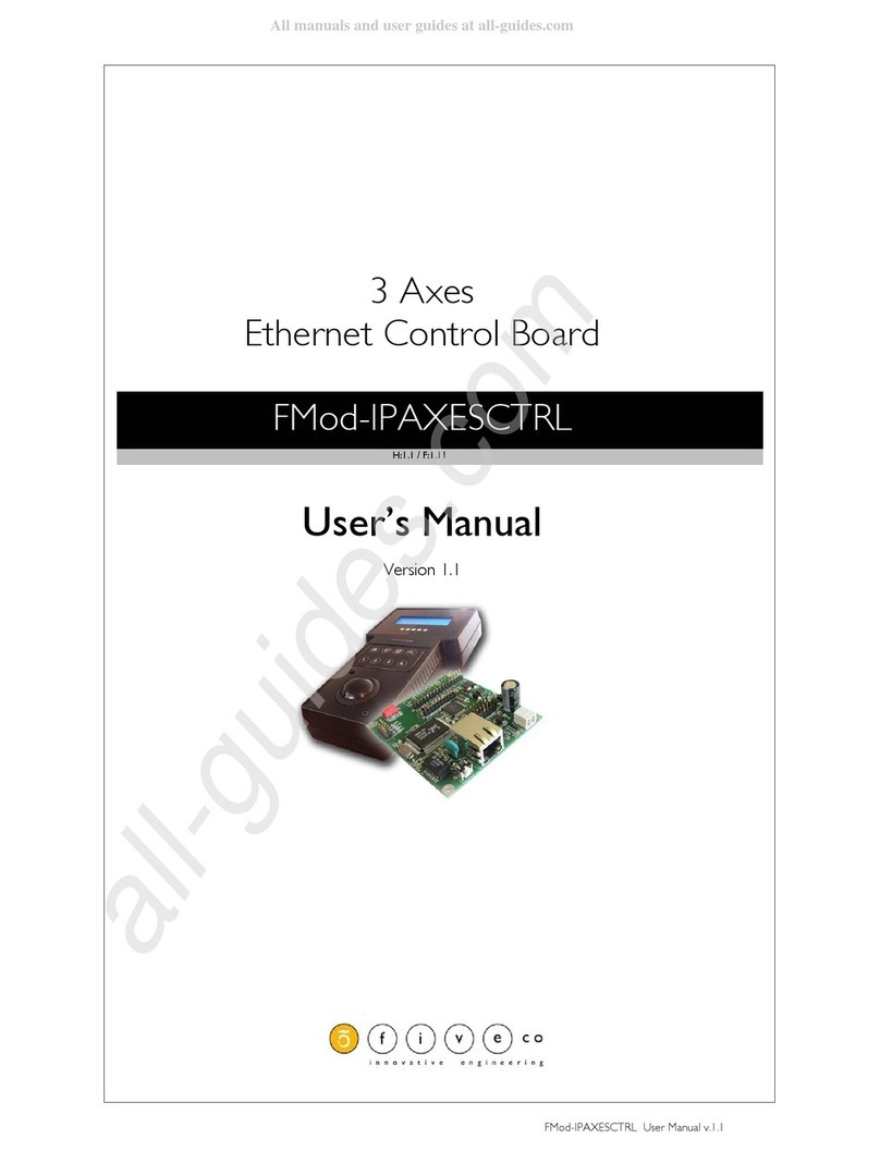
FiveCo FMod-IPAXESCTRL User manual

2 / 70
FMod-IPAXESCTRL User Manual v.1.5
Version: 1.5
Last revision: October 16, 2019
Printed in Switzerland
© Copyright 2002-2019 FiveCo Sàrl. All rights reserved.
The contents of this manual may be modified by FiveCo without any warning.
Trademarks
Windows® is a registered trademark of Microsoft Corporation.
Ethernet® is a registered trademark of Xerox Corporation.
Java® is a registered trademark of Sun Microsystem.
Philips® is a registered trademark of Koninklijke Philips Electronics N.V.
Borland® is a registered trademark of Borland Software Corporation.
Warning
This device is not intended to be used in medical, life-support or space products.
Any failure of this device that may cause serious consequences should be prevented by implementation of
backup systems. The user agrees that protection against consequences resulting from device system failure
is the user's responsibility. Changes or modifications to this device not explicitly approved by FiveCo will
void the user's authority to operate this device.
Support
Web page: https://www.fiveco.ch/product-fmod-ipaxesctrl.html
e-mail: support@fiveco.ch

3 / 70
FMod-IPAXESCTRL User Manual v.1.5
Revision history
Revision
Date
Author
Note
Firmware
version
Applet
version
Application
version
1.0
16.11.04
XG
- First revision history
Since 1.8
1.3
-
1.1
21.04.05
XG
- Add IP SUBNETMASK register (0x13)
- Add TCPCONNECTIONSOPENED register
(0x1A)
- Easy change IP with broadcast
- Add relative coordinate with relative zero
- Add AXISxPOSITIONOFFSET registers
(relative offset)
Since 1.11
1.6
-
1.2
30.09.05
AG
- Text and layout correction
- Add checksum function example
Same
Same
-
1.3
27.01.06
AG
- Correct function ID for easy change IP answer
frame.
Same
Same
-
1.4
21.12.07
AG
- New address
Same
Same
-
1.5
16.10.19
AG
- Remove Java Applet and add new application.
Same
Same
1.0

4 / 70
FMod-IPAXESCTRL User Manual v.1.5
Table of Contents
1. Package and operating conditions..............................................................................................................5
Package contents.................................................................................................................................................5
Operating conditions ........................................................................................................................................5
2. Overview.................................................................................................................................................................6
Connection architecture (Ethernet).........................................................................................................7
Board Layout.........................................................................................................................................................8
3. Quick start ..............................................................................................................................................................9
Power and network........................................................................................................................................ 10
Changing IP address........................................................................................................................................ 11
4. Hardware ............................................................................................................................................................. 12
Power supply...................................................................................................................................................... 12
LCD Display........................................................................................................................................................ 12
Keyboard .............................................................................................................................................................. 13
Trackball................................................................................................................................................................ 14
LEDs........................................................................................................................................................................ 15
SOS button ......................................................................................................................................................... 16
5. TCP/UDP Server ............................................................................................................................................. 17
General.................................................................................................................................................................. 17
TCP-HTTP port (# 80)................................................................................................................................ 17
TCP & UDP Control port (# 8010)..................................................................................................... 18
Easy IP address config (UDP # 7010) .................................................................................................. 20
Checksum calculation .................................................................................................................................... 21
6. Java Applet........................................................................................................Erreur ! Signet non défini.
Overview.............................................................................................................................................................. 23
Main Panel............................................................................................................................................................ 24
Board’s communication settings Panel.................................................................................................. 27
Keyboard settings panel................................................................................................................................ 26
LCD text Panel ................................................................................................................................................. 24
Modes & Axes settings Panel..................................................................................................................... 25
7. Reference zero absolute/relative............................................................................................................. 29
8. Registers management................................................................................................................................... 30
Memory Organization ................................................................................................................................... 30
Full Register Description .............................................................................................................................. 31

5 / 70
FMod-IPAXESCTRL User Manual v.1.5
1. Package and operating conditions
Package contents
1 Axes Ethernet Control board : FMod-IPAXESCTRL
This manual
(optional) Power Supply :
Power over Ethernet IEEE802.3af Hub-injector
(110-240 VAC, 50/60Hz -> +48v, 350 mA)
Operating conditions
Operating temperature -20 – 70 °C
Supply voltage Vcc 7-48 VDC
Input capacity (Power +,-) ~220uF, ~50mOhm ESR
Power consumption (~0.8W) 65mA when idle @ Vcc 7 V
Without LCD & Trackball 25mA when idle @ Vcc 24 V
15mA when idle @ Vcc 48 V
Power consumption (~1.2W) 150mA when idle @ Vcc 7 V
With LCD & Trackball45mA when idle @ Vcc 24 V
25mA when idle @ Vcc 48 V

6 / 70
FMod-IPAXESCTRL User Manual v.1.5
2. Overview
The FMod-AXESCTRL is a board used to control a maximum of 3 DC-
motorized axes (card FMod-IPDCMOT or FMod-IPECMOT). The main
advantage of this card is its communication protocol (Ethernet: TCP/IP-
HTTP) which allows it to be connected to a standard Ethernet network. In
addition, the board follows the IEEE 802.3af standard which allows it to be
powered through the Ethernet cable (PoE-Powered Device).
The FMod-IPAXESCTRL board works without the use of a computer (PC
or Mac). It communicates independently with the selected FMod-IPxxMOT
devices (motor control cards) through the Ethernet network. It can also be
easily configured with any standard web-browser, using its internal web-
pages (http server onboard).
A (4x20char) LCD can be connected in order to locally display information,
and a trackball + keyboard are the available inputs to handle the axes.
This diagram shows all peripherals that can be connected to the board.
The trackball, the LCD screen and the Keyboard (4x20)
FMod-PAXESCTRL
•Peripherals management
•http server
•IEEE 802.3af power supply
LCD display
4*20 character
Trackball
Quadrature signal
Keyboard
4*4 buttons
or
4*2 buttons
4 Leds

7 / 70
FMod-IPAXESCTRL User Manual v.1.5
Connection architecture (Ethernet)
The figure below shows the connection diagram of the FMod-IPAXESCTRL
board. The user interacts with the MMI (Man Machine Interface), e.g. the
LCD, the Keypad and the Trackball, which are connected to the Axes
control card. This card is connected together with the Motor control card
(FMod-IPDCMOT48/1.5) to a standard/industrial Ethernet Switch (available
on the market from 30.- USD) and is used in applications such as XYZ-
Tables.
The axes control board and the motor control boards are
connected together to an “Ethernet 10BaseT compliant Switch”.
The communication between them is done through the UDP-IP
protocol.
An optional computer (PC, Mac, …) can be connected to the same
network (to the Ethernet 10BaseT compliant Switch) in order to
configure the parameters of the axes control card
The same Switch used to connect the FMod-IPAXESCTRL and the
FMod-IPDCMOT48/1.5 can be connected to the Internet network
(under an ADSL modem/router or a professional Router) and
therefore make the system accessible from anywhere (remote).
Note : It is also possible to connect the FMod-IPAXESCTRL directly to an FMod-
IPxxMOT motor control card through a simple Ethernet Cross Cable (not using
the switch). In this case, the system will only be able to control one (1)
motor/axis.

8 / 70
FMod-IPAXESCTRL User Manual v.1.5
70.5
75.7
69.5
64.3
∅3.2
Board Layout
JP3
SOS button
J1 IN Power +
IN Power -
J7 Ethernet RJ45
J4 Keyboard 2x4
Keyboard 4x4
J5 Trackball
J3 LEDs indicator
J8 LCD display
Max height: 20mm

9 / 70
FMod-IPAXESCTRL User Manual v.1.5
3. Quick start
This section is intended to help users to quickly plug the module into their
system and establish a connection between the computer used for the initial
configuration and the card. Detailed information about hardware and
software can be found further in this document.
You can find the board factory communication settings on the label that is
found on the board and on the box.
The MAC Address is the 48bits unique identifier on Ethernet networks. The
IP Address can be modified. The complete procedure is described further in
this manual.
Note: If the module has already been configured and the IP address has been
changed to an unknown value, you can retrieve an SOS IP address (on label) by
pressing the “SOS button” when the card is operating normally.
FMOD-IPAXESCTRL
INPUT(supply) : 7-48V DC, 1.5 W
MAC: 00-50-C2-30-8x-xx / IP : 169.254.5.1
This device is not intended to be used in a medical, life-support or space product. Any failure
of this device that may cause serious consequences should be prevented by implementation
of backup systems. The user agrees that protection against consequences resulting from
device system failure is the user's responsibility.

10 / 70
FMod-IPAXESCTRL User Manual v.1.5
Power and network
1. Connect the card to a computer using a RJ45 cross wired cable
(direct-link), or with a straight cable to an Ethernet-switch.
Connect the cable to the card and to the PC
Connection with an Ethernet crosscable
2. Connect a power supply (7-48V) or a POE injector to the module.
Discrete power supply OR PoE with a Power injector

11 / 70
FMod-IPAXESCTRL User Manual v.1.5
Changing IP address
To easily change the factory IP address, user can use the Win32 software
provided on the CD-Rom.
1. Plug your new card on your PC network.
2. Start the Win32 application.
3. Click on "File->Easy change IP address".
4. The software will scan the network and display a list of all FiveCo's
devices found.
5. Select the MAC address corresponding to your new card.
6. If you have more than one network adapter on your PC, the
software will ask you to select the one that is connected to the same
network as the FMod-IPAXESCTRL.
7. The software will suggest a new IP address without the last byte.
Choose a new IP (that is not already used on your network!!) and
click the "Change IP address" button.
That’s it! The card has a new address and a new subnet mask (the same as
your PC). They are automatically saved into EEPROM.
You can now connect to the card with the Win32 software or open its web
page by typing its new IP address into a web browser.
Remark:
The IP address will not be changed if a TCP connection exists with the card.

12 / 70
FMod-IPAXESCTRL User Manual v.1.5
4. Hardware
There are different configurations, depending on the needs of your
application:
FMod-IPAXESCTRL + Keyboard
FMod-IPAXESCTRL + Keyboard + trackball
FMod-IPAXESCTRL + Keyboard + LCD
FMod-IPAXESCTRL + Keyboard + LCD + trackball
An independent connector for each peripheral is present on the card. No
particular configuration is needed to enable/disable each of them. You simply
have to connect a peripheral before powering-up the card.
Note: It is better NOT to unplug the peripherals while the system is powered.
Power supply
The card can be powered in two modes:
WARNING: do NOT use both modes at the same time!
1. POE (Power Over Ethernet) 48V only, 350 mA on connector J7
(RJ45), pins 4&5(+), 7&8(-). Swapped polarity works too.
Compatible with IEEE 802.3af mode B & A.
2. Discrete 7-48 V DC on connector J1. Negative pole is near the
J7(RJ45) connector.
LCD Display
The FMod-IPAXESCTRL board drives
an LCD display with 20 columns and 4
lines. LED backlight is also powered
from the FMod-IPAXESCTRL, and is
always ON.
Different LCD colors are available, but
FiveCo recommends Crystalfontz’
LCDs (www.crystalfontz.com)
The LCD used by FiveCo is Crystalfontz’ model CFAH2004A-TMI-JP (with LSI
HD44780 driver inside), blue-backlit with white characters (pictured on the
left).

13 / 70
FMod-IPAXESCTRL User Manual v.1.5
The connector on the FMod-IPAXESCTRL board has the same pin
configuration as the one of the LCD (allowing an easy flat-cable connection),
but the LCD has to be used in 4bits data mode only.
Board J8 connector pinout:
1
GND
2
5V
3
VO (Contrast)
4
RS
5
R/W
6
E
7
- (nc)
8
- (nc)
9
- (nc)
10
- (nc)
11
DB4
12
DB5
13
DB6
14
DB7
15
Backlight 5V with a 33Ohm
resistor already in series.
16
Backlight GND
Keyboard
The board offers the possibility to
connect two kind of MATRIX
KEYBOARDS: 2x4 or 4x4.
Board J4(up) connector pinout (2x4
version):
1
Column 0
2
Column 1
3
Line 3
4
Line 2
5
Line 1
6
Line 0
Board J4(down) connector pinout (4x4 version):
1
Column 0
2
Column 1
3
Column 2
4
Column 3
5
Line 2
6
Line 3
7
Line 1
8
Line 0

14 / 70
FMod-IPAXESCTRL User Manual v.1.5
Axe 1
Axe 2
The following diagram shows the position of each key on the keyboard
(useful for the configuration).
Trackball
A two axes trackball enables the user to
manage axis 1 and axis 2 (axis 3 is
manageable only from keyboard). Each
channel must have quadrature signal (A,
B).
PEWATRON model LP150-5FV00 is
the reference for this board. It is also
possible to use other kinds of trackballs
with different resolutions or even gravity
independency (ex: Megatron model 816TC).
Board J5 connector pinout and trackball
connector pinout and axes:
1
- (not connected)
2
- (nc)
3 - (nc)
4
5V
5
Xa
6
Yb
7
Ya
8
Xb
9
- (nc)
10
GND
A
B
C
D
E
F
G
H
I
J
K
L
M
N
O
P
B
F
J
N
A
E
I
M
Connector
Connector
Column: 0 1 2 3 0 1
Line: 0 1 2 3

15 / 70
FMod-IPAXESCTRL User Manual v.1.5
LEDs
The FMod-IPAXESCTRL is provided with a connector for 4 LED (J3). They
give information about the mode (1, 2, 3) of the board and the state (activity
or not) of the axes. Here is the LED’s layout:
Board Mode
The different modes define the way the input (trackball and Keyboard) and
output devices (LCD display) interact with the physical system (commands
sent to the motor). See “Axes parameters Panel” in “Java applet” chapter
for more detailed information.
Mode 1 = LED0 on, LED1 off
Mode 2 = LED0 off, LED1 on
Mode 3 = LED0 off, LED1 off
Axis State
The LEDs are especially useful in order to determine the mode on how the
axes are controlled by the trackball (axes 1 and 2). When an axis is found
and is ready to receive data, then its corresponding LED is on; if an axis is
“suspended”, its LED is off. It is possible to drive an axis (for ex: axis1)
without modifying the other one (ex: axis2) which has been put in a
“suspended” state with the press of a keyboard button.
Notes:
No LED exists for axis 3 since it cannot be driven by the trackball.
The LEDs display the information in any case, even if the LCD is not
connected.
The board drives the lower pin (Cathode /-) of
the LED while the upper one (Anode /+) is
connected to 5V. An onboard 1kOhm resistor is
connected in series to limit the current to
~3mA.
Board J3 Connector:
1
Led 0 resolution mode 1
2
5V
3
Led 1 resolution mode 2
4
5V
5
Led 2 axis 1 ON/OFF
6
5V
7
Led 3 axis 2 ON/OFF
8
5V
0 1 2 3
Board Mode Axis
0 1
0 1
0 1
1k
5V
Board Connector
(one for each led)
Controller
3 mA

16 / 70
FMod-IPAXESCTRL User Manual v.1.5
SOS button
This button has 2 different purposes, depending on
the moment when it is pressed: at system power-
up or when the system is already running.
POWER UP ACTION (the SOS Button is pressed
during power up)
This action is useful when the “out-of-factory” state
of the card needs to be exactly restored.
The RestoreFactoryParamters (0x05) function is
automatically called, and the actual IP address is overwritten with the SOS IP
address written on the sticker of the card (169.254.5.1). After that, all these
parameters are automatically saved in the User’s parameters memory with
the SaveUserParameters (0x03) function.
RUNNING ACTION (the SosButton is pressed while running)
This action is useful when the user has lost the actual IP address of the card,
and temporarily needs to connect to it without changing all of the card’s
parameters.
Only the IP address is overwritten, using the SOS IP address that appears on
the card’s sticker (169.254.5.1). This new IP will be valid only after all TCP/IP
connections (web pages included) have been closed.
In this case the SOS IP address is not automatically saved, so if you need it,
you will have to manually call the SaveUserParamters (0x03) function.
Otherwise, the previous IP will be reloaded upon the next power-up.
Warning:
Do not use the “SOS IP address” as the normal IP for your module (during
normal board operation). If you plug another module on the same network,
both will have the same IP and will therefore be impossible to both
configure.
SOS button

17 / 70
FMod-IPAXESCTRL User Manual v.1.5
5. TCP/UDP Server
General
The board provides an Ethernet port (RJ45 – connector J7) which allows
access to all parameters (registers) of the module through a TCP or UDP
connection.
Here you will find a small comparison table between these two protocols
(non exhaustive):
Two ports are available when using the TCP protocol:
Port #80 for HTTP communication.
Port #8010 Access to the control port
Only one port is accessible through the UDP protocol:
Port #7010 Access to the control port
You will find a detailed description of the different ports in the next pages.
Note: The board allows up to 4 simultaneous TCP connections. That means, for
example, that 4 users can connect to the #80 port to see the web page, or 4
users can be connected to the #8010 port and control the I/Os, or even that
two see the page and two control the I/Os, etc. In UDP protocol, there is no
limitation on the number of users connected.
HTTP port (TCP # 80)
This port is used to access the web page stored on the module.
The user can simply access that port and ask for a particular page, through
the use of a standard Web browser, and typing the IP address of the card:
Ex: type http://169.254.5.1/index.htm in the address bar of the browser and the
“index.htm” page will be loaded.
Features UDP TCP
CheckSum (Data integrity) YES YES
Multiport (data multiplexing) YES YES
Flow control NO YES
Acknowledge Data NO YES
Multipacket order reconstruction NO YES

18 / 70
FMod-IPAXESCTRL User Manual v.1.5
Control port (TCP # 8010 or UDP # 7010)
This port is used to access the registers described in the chapter “Registers
management” of this manual.
Note: If you plan to configure all registers only from the onboard Webpage, you
can skip this section and go to the Java-Applet section. (The Java-Applet also
uses this port to read and write the different settings!)
TCP/IP works in big endian: most significant byte first, followed by least
significant byte(s). The access is done by sending a packet that follows a
simple (6 byte header) protocol.
Structure of each packet:
1) Function ID (2 bytes) Code of the function that has to be executed.
2) Transaction ID (2 bytes) Number that defines this packet
3) Length of the parameters (2 bytes) Number of the parameters + data bytes
4) Parameters (X Byte) Parameters + Data
5) Checksum (2 bytes) Control Sum of packet’s bytes
Function ID
The specific code for each function can be found on the next page of this
manual.
Transaction ID
The user defines himself the values of the Transaction ID. Normally, each
packet/transaction (communication request) should have a different ID (even
though this is not mandatory). When the FMod-IPAXESCTRL receives a
command/packet, it sends back an answer (at each request). This answer
contains the same Transaction ID than the corresponding command
previously sent. In that way, the user is able to check the execution of each
command.
Length of the parameters
This 2byte value corresponds to the length (in bytes) of the next section of
the packet (parameters only).
Parameters
This part of the packet contains all the parameters (mainly the data that are
sent).
Checksum
This 2 bytes value is the Check Sum of all the bytes of the packet (more
information on next pages).

19 / 70
FMod-IPAXESCTRL User Manual v.1.5
READ register(s) value command.
Byte#
Number of bits
Example
0x00
Read (0x0021)
16 bits
0x0021
0x02
TransactionID
16 bits
0x1B34
0x04
Number of registers to
read (X)
16 bits
0x0001
0x06
X * Registers Addresses
X * 8 bits
0x02
0x06+X
Checksum
16 bits
0x…
The maximum number of registers that can be read at one time is almost
30. The answer sequence should not be greater than 180 bytes. If the
number of registers is too high, the FMod-IPAXESCTRL will answer only
with the value of some of them.
The module answers with the following sequence:
Byte#
Number of bits
Example
0x00
Read Answer (0x0023)
16 bits
0x0023
0x02
TransactionID (same as
demand)
16 bits
0x1B34
0x04
Number of bytes in answer
16 bits
0x0019
0x06
Register address
8 bits
0x02
…
Register value
8–128 bits (16B)
0x12345
The two previous entries are replicated for each register that has
been asked for reading
…
Checksum
16 bits
0x…
WRITE register(s) value command.
Byte#
Number of bits
Example
0x00
Write (0x0022)
16 bits
0x0022
0x02
TransactionID
16 bits
0x1B34
0x04
Number of bytes in
command
16 bits
0x0003
0x06
Register Addresses
8 bits
0x02
0x07
Register value
8 – 64 bits
0x1234
The two previous entries are replicated for each register that has
been asked for reading
…
Checksum
16 bits
0x…
The maximum length of this sequence is 180 bytes.

20 / 70
FMod-IPAXESCTRL User Manual v.1.5
The module answers with the following sequence:
Byte#
Number of bits
Example
0x00
Write Answer (0x0024)
16 bits
0x0024
0x02
TransactionID (same as
demand)
16 bits
0x1B34
0x04
0x0000
16 bits
0x0000
0x06
Checksum
16 bits
0x…
Easy IP address config (UDP # 7010)
A really useful feature of the UDP port #7010 is the "Easy IP config" one.
The user who wishes to design his own software can use this feature for a
"quick start/install" method. Indeed, since this protocol uses a broadcast UDP
packet, the device should receive its new IP address and subnet mask, even if
it is not part of the same subnet.
Procedure:
Send a UDP broadcast message (using a local or direct broadcast IP address)
to your network (to which the FMod- IPAXESCTRL is connected) with the
following command:
Byte#
Number of bits
Example
0x00
Change IP fct (0x002A)
16 bits
0x002A
0x02
TransactionID
16 bits
0x0000
0x04
Length of params (0x000E)
16 bits
0x000E
0x06
Device Mac Address
6 bytes
0x0050C2308101
0x0C
Device new IP Address
4 bytes
0xC0A81064
0x10
Device new SubnetMask
4 bytes
0xFFFF0000
0x14
Checksum
16 bits
0x…
If the FMod- IPAXESCTRL recognizes its MAC address, it will answer this
command with a simple acknowledges. It will then change its IP address and
subnet mask IF NO TCP CONNECTION IS MADE TO THE BOARD.
Byte#
Number of bits
Example
0x00
Change IP fct ack (0x002B)
16 bits
0x002B
0x02
TransactionID
16 bits
0x0000
0x04
Length of params (0x0000)
16 bits
0x0000
0x14
Checksum
16 bits
0x…
Other manuals for FMod-IPAXESCTRL
2
Table of contents
Other FiveCo Control Unit manuals
Popular Control Unit manuals by other brands
Masibus
Masibus MAS-AO-08-D manual
Trinamic
Trinamic TMCL TMCM-6212 Firmware manual
Cooper
Cooper Z-WAVE RF232 Quick Start Guiude
SSS Siedle
SSS Siedle NG 602-0 manual
Continental Refrigerator
Continental Refrigerator DTCO 1381 Process Guide

Honeywell
Honeywell HON 530-E-WG OPERATING AND MAINTENANCE INSTRUCTIONS/ SPARE PARTS

