A-EON AEON-50310 User manual

AEON-50310
MANUAL
Support 46” to 80” TVs
Load Capacity: 25-90 lbs
Pull Down Fireplace TV Mount with
Vertical and Horizontal Adjustment
9
18
2 of 18
• This wall mount will only support flat panel displays. The maximum load capacity is 100 lbs.
TV.
• TV Mount can be mounted onto two wooden studs, with center to center distance between 26”
PLEASE NOTE: IMPROPER INSTALLATION WILL VOID WARRANTY.
• Please do not begin installation until you have thoroughly read and understood these instructions.
• Improper installation may cause serious injury and/or damage.
• It is recommended that a qualified contractor install the AEON-50310 TV Mount.The manufacturer does not
accept responsibility for incorrect installation.
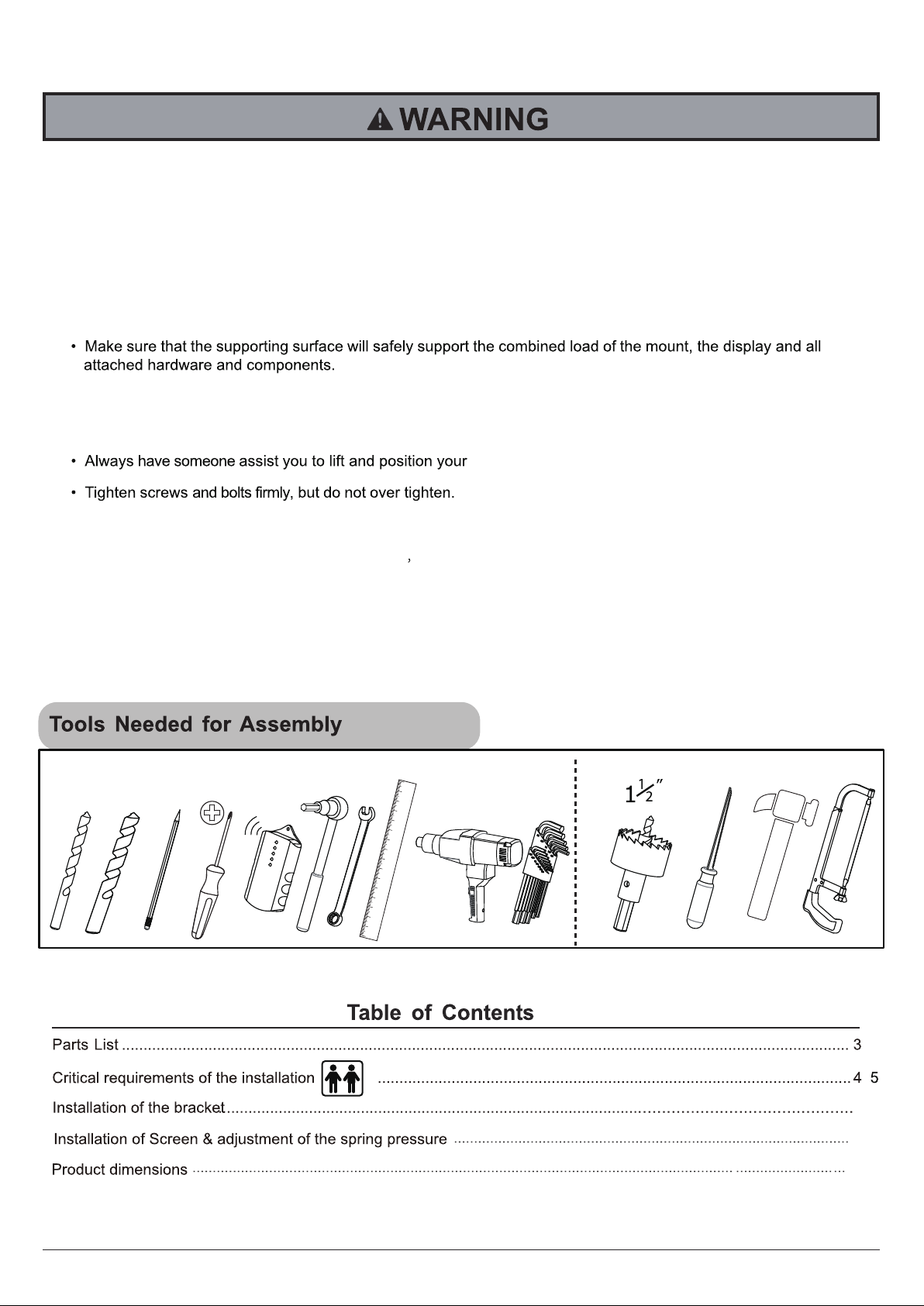
Required Tools Optional Tools
3/16” 3/8”
• If mounting to a wall of wood stud construction,be sure that mounting bolt are anchored the center of the studs,
When installing the TV mount on a concrete wall the wall must be at least 8" thick with a minimum compressive
strength from 2500 to 3000 psi (17.2 to 20.7 Mpa),the concrete wall must meet ASTM C39. When installing the TV
mount on a cinder block wall, the cinder blocks must meet ASTM C216 specifications and have a minimum
nominal width of 8”. Be sure to mount in a solid part of the block, generally 1" minimum from the side of the
block.Do not drill into mortar joints! If plaster/dry wall is thicker than 0.6",custom fasteners must be supplied
by the installer.
,
6

3 of 18
M4
Q
1
O
P
Q
P
G
Slider Plate
Slider Plate
123
45
67
backplate(x1)
Wrench
M10(x1)
vertical rails(x1)
4
2
M10x60
Expansion pipe
2
4

4 of 18
• Make sure that the supporting surface will safely support the combined load of the equipment
and all attached hardware and components.
• Installation will require a minimum of two people.
AEON-50310 CAN BE
MOUNTED ONTO TWO
WOODEN STUDS, WITH
CENTER TO CENTER
DISTANCE BETWEEN 26”
TEMPERATURE AT THE
FRONT EDGE OF MANTLE
SHOULD NOT EXCEED 110˚ F

5 of 18
Recommended TV size from 46” to 80”. Recommended TV weight between 25-90lbs
Please refer to your TV's Owner's manual for details.
Backplate
Backplate
Backplate
Backplate
Backplate
from 46” to 80”
MANTLE MAY NOT
EXCEED 14in TO INSURE
PROPER INSTALLATION
25-90
LBS
14 inches
MAXIMUM
The required space height for the TV Mount
depends on the width of the mantle.
Refer to the chart below to determine the necessary
distance for the TV mount installation.

Determine where you want your TV mounted on your wood stud wall.
Measure the centerline of the mantle. Mark lightly with pencil so it is easy to erase.
6 of 18

Locate two studs above mantle-one left and one right of center line. Once
you have found the left and right edge of the stud-devide the distance to find
the center. Mark the center line.
CUTOUT SHOWN
FOR REFERENCE
7 of 18

8 of 18
6mm(3/16”)
Reference
chart p.5
CL CL
CL
plywood wall wood stud wall
CL
CAUTION
2.7”
6mm
(3/16”)
Refer to the chart p.5 to determine the necessary distance for the
TV mount installation. Make sure that the four mounting holes do
not have a large deviation and are level. Drill 3/16 inch holes.

9 of 18
4
CL
Reference
chart p.5
M
CUTAWAY VIEW
INCORRECT
CORRECT
wall plate
plaster/
drywall
concrete
wall plate concrete
plaster/
drywall
Do not drill into mortar joints!
2.7”
10mm(3/8”)
10mm
(3/8”)
CAUTION
Refer to the chart on page 5 to determine the necessary height above the mantle for
installing the backplate. When installing on concrete or brick please use the wall plug
anchors (M) provided in the hardware kit. Drill (4) 3/8” pilot holes in the concrete block
or brick. Do not drill into mortar joints.

10 of 18
The middle
About to adjust
CAUTION
Don't over tighten!
A
O
(magentic spirit level)
LL
3
Attach backplate to the wall. Use appropriate
hex bolt screws. Insert and tighten all lag
screws into the CENTER of the studs. Guide
cables and wires through the hole as shown
in the illustration.If the TV bracket position is
not what you want, you can use the M5
wrench (O) loose screws, mobile connection
plate to the location you want.

11 of 18
Assemble K/5/6/O using (N) wrench M10.
(wrench M10)
O
6
5

7
12 of 18
Tighten the four allen pan head
screws (M8x10) with Hexagon
wrench (O).

8
13 of 18
If you find that your TV can not cover the entire bracket, please according to the size
of the TV set you adjust TV on mobile plate for the TV to cover the entire stent.
TV
TV
O
M4
Please adjust in front of the
television to the appropriate
location

9
G
F
14 of 18
P
4
1
I N
H
10
Align the vertical rails with the four mounting holes on
the back of your TV . Select the appropriate TV
Mounting Screw size. Use a spacer if required. Hand
tighten 4 screws with washers. Do not over tighten as
you could damage your TV.
Attach handle and connecting rod (1,4) to
the vertical rails with the appropriate
screws. (H,I,N,P)

15 of 18
12
Using two people, lift the TV as shown and hang the vertical rails onto the front panel and
ensure they “lock” into place. Next, insert the two Philips type screws (I) behind the front plate
and tighten them securely into place with a Philips screwdriver. (See inset below)

13
16 of 18
_+
_+
The energy saving wrench can be replaced by
provided O (hexagon wrench M8).
10.0/22.0
16..0/35.2
22.0/48.5
26.0/57.3
32.0/70.6
37.0/81.6
41.0/90.5
45.0/100.0
KG/LBS
STOP LINE
!
STOP LINE
!
ATTENTION
Refer to this
above cylinder
as a pointer
According todifferent load weight,
pleaseadjustthe gas spring into
suitable position within the
scope
of the scale, excessive adjustment
is forbidden !
Snap the plastic wall panel covers (7) onto the horizontal rails of the backplate. Adjust the
counterweight (gas spring) pressure level based upon on the weight of the TV so the TV
“floats” in any position.
Please note this step may take some time until the correct setting is achieved.

17 of 18
14
Tightening
(clockwise)
+
Loosing
(counter clockwise)
-
The tilt angle of the TV can be easily adjusted via the ratcheting knobs on the bracket.
Please refer to the diagram below.

18 of 18
for max to 80”screens
load capacity 25-90 lbs
Product Dimensions
MAX 600
MAX 400
715.7
696.5
30
152.6
446.3
614.5
30
+5~-15
tilt:+5~-15
Table of contents
Other A-EON TV Mount manuals


