manuals.online logo
Brands
  1. Home
  2. •
  3. Brands
  4. •
  5. Displays2go
  6. •
  7. TV Mount
  8. •
  9. Displays2go HVAWM3260S User manual

Displays2go HVAWM3260S User manual

1
PLEASE READ THESE INSTRUCTIONS CAREFULLY AND KEEP FOR FUTURE REFERENCE! IF
YOU DO NOT UNDERSTAND THE INSTRUCTIONS, OR DO NOT FEEL THAT YOU CAN FOLLOW
THEM SAFELY, CONTACT A QUALIFIED CONTRACTOR. THE WARRANTY WILL BE HONOURED IF
ACCOMPANIED BY AN ORIGINAL SALES RECEIPT, AND ONLY IF THE INSTRUCTIONS HAVE
BEEN FOLLOWED EXACTLY.
·The HVAWM3260S
is designed to mount a panel onto a vertical wall. Hardware for mounting to
a wood stud is included. For mounting to any other surface, it is recommended you contact a
qualified contractor.
· The wall or mounting surface must be capable of supporting the combined weight of the mount
and the display, otherwise the structure must be reinforced.
· Safety gear and proper tools must be used. A minimum of two people are required for this installation.
Failure to use safety gear and/or attempting this installation alone can result in property damage,
serious injury, or death.
· Follow all instructions and recommendations regarding adequate ventilation and suitable locations for
mounting your flat panel. Consult the owner
‘s manual for your flat pane .noitamrofni erom rof l
· This product will hold flat panels up to 60” and weighing up to 150 l .sb
· VESA 200mm x 200mm-600mmx400mm.
Tools Required
· Stud finder ("edge to edge" stud finder is r )dednemmoce
· Phillips scre revirdw
·Penc li
· Ham )ylno noitallatsni etercnoC( llirD rem
· 1/ etercnoc rof tib llird ”8/3 ,sduts doow rof tib llird "4
· 7/16" swercs doow rof revird tib ro hcnerw tekcos
· L leve
· Tape measure
INSTRUCTIONS
HVAWM3260S
Parts List
Wall Plate (x1) Adaptor Plate (x1) Adaptor Brackets (x2)
Slider Plates
(x4) Anchor (x4)
Spacers (x4) Allen Key (x1)
M5*15mm
(x4) M5*25mm
(x4) M6*12mm
(x8)
M6*25mm
(x4) M8*15mm
(x4)
Lag Bolt
8*70mm (x4)
A
M8*12mm
(x4)
B
M8*30mm
(x4)
C
Metal Washer
φ8mm (x4)
D
Metal Washer
φ6mm (x8)
E F G H
I J K L
M N
2
Step 1A - Mounting the wall plate to wooden studs (Fig. 1)
The HVAWM3260S can be mounted onto two wooden studs, with center
to center distances between 16" (406mm).
Using an electronic stud finder, locate the center of the two wooden studs at the
desired mounting location. Mark the stud center positions directly on the wall.
Connect the stud marks with a horizontal line and find the center between them
to represent where you wish the center of the screen to be located. Be sure to
measure and mark the center of this horizontal line.
Place the wall plate on the wall. Pin the wall plate to the center mark on the wall.
Using a level (bubble or laser ), level the guide, and
then press the adhesive backing against the wall to
hold the guide in place. Using a 1/4" (6mm) drill bit,
drill 4 pilot holes into the center of the studs, down to
a depth of 3" (76mm).
NOTE: It is not recommended to use a drill driver or impact
wrench to tighten bolts. Tighten lag bolts so that wall plate
is firmly attached to wall, but DO NOT over-tighten. The lag
bolts can be damaged by over-tightening which will strip
their threading. Final tightening of lag bolts
should be done by hand using a ratchet
wrench and socket.
Fig. 1
Step 1B - Mounting the wall plate to concrete (Fig. 2)
Place the wall plate on the wall. Pin the wall plate to the center mark on the wall. Using a level (bubble or
laser), level the guide, and then press the adhesive backing against the wall to hold the guide in place.
Using a 3/8" (10mm) masonry drill bit, drill 4 mounting holes 3-1/8" (80mm) deep into the concrete/masonry
surface.
NOTE: It is not recommended to use a drill driver or impact wrench to tighten bolts. Tighten lag bolts so that wall plate is
firmly attached to wall, but DO NOT over-tighten. The lag bolts can be damaged by over-tightening which will strip their
threading. Final tightening of lag bolts should be done by hand using a ratchet wrench and socket.
Lag Bolt With Washer
M8*70mm--(M)
6mm (1/4”)
Hole Wood Stud
Fig. 2
Lag Bolt With Wahser
M8*70mm--(M)
Wall Anchor
(N)
10mm (3/8”)
Hole
CAUTION: Two people recommended
for lifting
CAUTION: Two people recommended
for lifting
3
Step 2 - Assembling the Adaptor Plate (Fig.3)
Insert slider plates (x4) into the adaptor rails, then
insert the adaptor brackets into the adaptor rails.
Attach the adaptor bracket and slider plates with four
M6*12mm screws and four φ6mm metal washers
using a Phillips screw driver.
Attach the adaptor bracket onto the panel using
the provided M5, M6, M8 screws.
Adaptor rail
Slider plate
(K)
M6*12mm
Screw--(C)
Adaptor bracket
φ6 mm Metal
Washers--(H)
Fig. 3
Mounting screws
(A~E,G)
φ6mm metal
washers--(H)
Adaptor brackets
NOTE: Determine the correct diameter of screw to use by
checking your panel’s user manual, or by testing the
screws provided. Make sure not to force any of the screws
into the panel.
NOTE: If the back of your panel is flat and the mounting
holes are flush with the surface, use the shorter panel
screws. If the back of your panel is curved, protruded, or
recessed, use the longer screws. You may also need to use
spacers (J) with the longer screws.
Now slide the opposite mounting rail into position,
align it with the mounting holes, and secure using the
mounting hardware.
Step 3 - Attaching the flat panel to the
mount
By hand, insert two M8*12mm screws and φ8 mm
metal washers into threaded holes on the adaptor
panel as shown in Fig.4. Leave approximately 3/8”
of exposed thread.
With the help of an assistant, carefully lift the
panel and attach it to the mount head cautiously.
Tighten the screws as shown in Fig.5. Fig. 4
Fig. 5
φ8mm metal
Washer--(I)
M8*12mm
Screw--(F)
φ8mm metal
Washer--(I)
M8*12mm
Screw--(F)
CAUTION: Two people recommended
for lifting
4
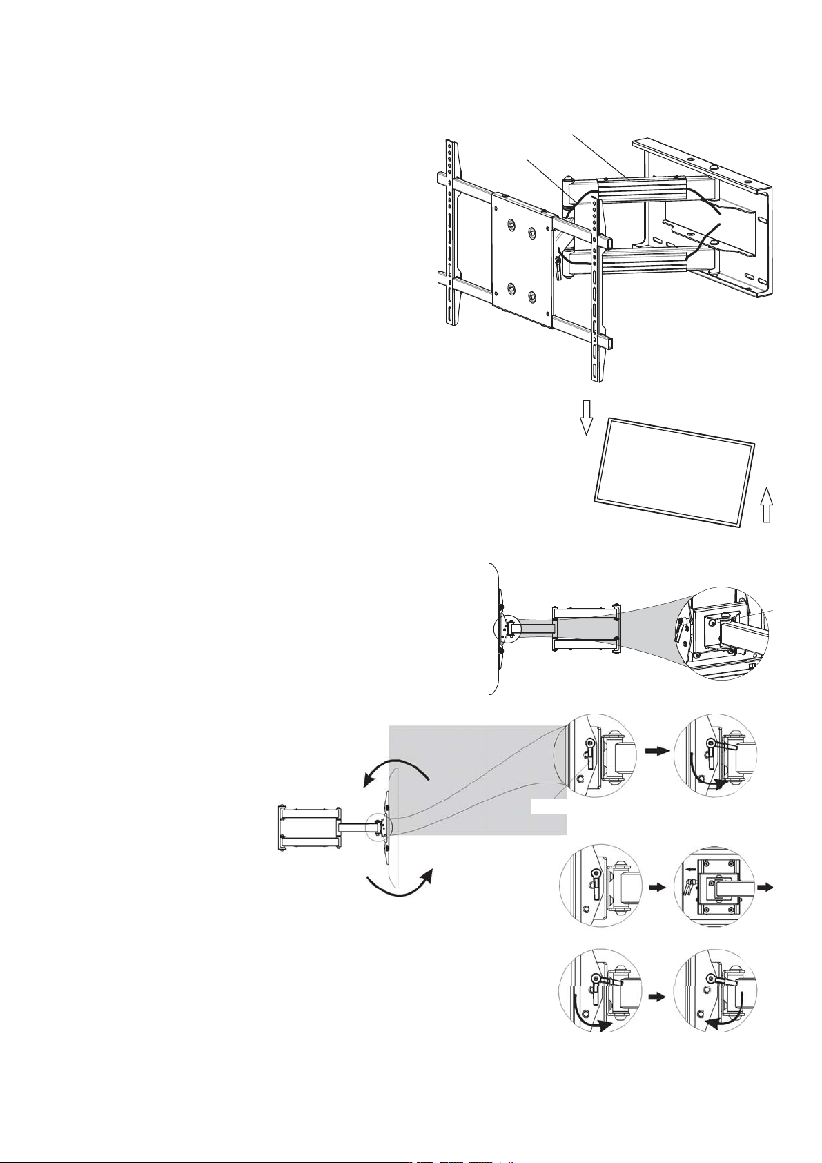
Step 4 - Using cable management (Fig. 6)
The HVAWM3260S includes a cable management system
where cable can be routed along the length of the arm
assembly.
Route the panel cable along the entrance of the cable
management slot.
NOTE: For optimal performance, route the AC power cable
separately from the audio and video cables
With all cables in place, pull the panel in and out to be
certain that the arm assembly moves freely, without
stretching or damaging the cables.
U-Cap cable management
Cable
Fig. 6
Step 5 - Adjusting the flat panel
The HVAWM3260S provides a wide range of adjustment possibilities
to suit your environment.
Roll Control - Horizontal levelling of the flat panel display.
Grasp the edge of the panel and roll it up or down into a level
position (Fig.7.1).
Loosen the screws as shown in Fig. 7.2 to allow roll control
adjustment. Tighten screws by hand when finished.
Tilt Adjustment - Raising or lowering the screen to improve
viewing angle. First release completely the tilt knob as shown
(Fig.9) Next, grasp the upper and lower edges of the panel,
and then turn it to the desired
tilt angle (Fig.8).
To lock the tilt angle, tighten
the tilt knob (Fig.10) securely.
NOTE : For heavier panels, never
fully release the tilt knob without
fully supporting the panel. The tilt
lever includes a ratchet function,
so that it can be lifted and
repositioned for the next turn. To
operate the ratchet, pull the lever
straight out, rotate it to an
unobstructed position, release the
lever, and then turn it in the
desired direction. Repeat as
necessary until the tilt tension is
set properly (Fig.10)
Fig. 7.1
Fig. 7.2
Fig. 8
Fig. 9
Fig. 10
a b
c d
Tilt knob Release tilt knob
Turn Tighten
5
Swivel - Adjust the flat panel display for off-center viewing
positions. Grasp the side edges of the panel and then swivel it
into its desired position (Fig.11).
Panning - Position the flat panel display at an angle to the wall
for viewing from opposite sides of the room.
Grasp the side edges of the panel and then swivel and pull the
panel into desired position (Fig.12).
Retracting the flat panel - Position the panel against the wall.
Grasp the side edge of the panel, swivel and pull it into the
center position (Fig.14). Then gently push the panel straight
back towards the wall into the retracted position (Fig.15).
NOTE : Use care when moving the panel to ensure that cables do not
become stretched or pinched. It is recommended that you allow a
small amount of slack in cables to allow for easy movement without
pinching.
Fig. 11
Fig. 12
Fig. 13-1
Fig. 13-2
Fig. 14
Fig. 15
Maintaining the HVAWM3260S
The arm assembly and wall plate may be cleaned with a soft sponge and mild
solution of soap and water.
Caution : Be sure not to get moisture on the electrical connections or the panel.
I
1 : 5
Metal Washer 6
M6*12mm
Slider Plates
Portrait and Landscape-Before portrait and landscape viewing,
make sure the adaptor bracket have already tightened with
adaptor rail by 4 pcs slider plates, M6x12 screws and washers(Fig.13-1).
Loose the level screws (Fig.10-b),and rotate 90 degrees for portrait
and landscape viewing,then tighten the level screws.
NOTE: Do not fully loose the level screws for heavier panels.

Other Displays2go TV Mount manuals

Displays2go MNTW803S User manual

Displays2go

Displays2go MNTW803S User manual

Displays2go LTB8MLT3TH User manual

Displays2go

Displays2go LTB8MLT3TH User manual

Displays2go Universal LPGP36WB User manual

Displays2go

Displays2go Universal LPGP36WB User manual

Displays2go TVSDP4060B User manual

Displays2go

Displays2go TVSDP4060B User manual

Displays2go IPBYSATO10 User manual

Displays2go

Displays2go IPBYSATO10 User manual

Displays2go LMCEL3763 User manual

Displays2go

Displays2go LMCEL3763 User manual

Displays2go DSTAND2BK User manual

Displays2go

Displays2go DSTAND2BK User manual

Displays2go HVAWM4290L User manual

Displays2go

Displays2go HVAWM4290L User manual

Displays2go WMONMTWH User manual

Displays2go

Displays2go WMONMTWH User manual

Displays2go TVSDP2642B User manual

Displays2go

Displays2go TVSDP2642B User manual

Popular TV Mount manuals by other brands

Symmons Temptrol Rapid Install RTS-076 installation instructions

Symmons

Symmons Temptrol Rapid Install RTS-076 installation instructions

B-Tech Ventry BTV501 Installation guide & parts list

B-Tech

B-Tech Ventry BTV501 Installation guide & parts list

B-Tech SYSTEM X BT8340 installation guide

B-Tech

B-Tech SYSTEM X BT8340 installation guide

PMV Mounts PMVMOUNT3246SA Mounting instructions

PMV Mounts

PMV Mounts PMVMOUNT3246SA Mounting instructions

Omnimount Play 25 user guide

Omnimount

Omnimount Play 25 user guide

VOGELS MA 2030 Series Full Installation Guide

VOGELS

VOGELS MA 2030 Series Full Installation Guide

Rocket Fish rf-tvmfm02 Quick setup guide

Rocket Fish

Rocket Fish rf-tvmfm02 Quick setup guide

Omnimount OM1100638 user guide

Omnimount

Omnimount OM1100638 user guide

Tripp Lite SRWBWALLBRKT installation guide

Tripp Lite

Tripp Lite SRWBWALLBRKT installation guide

One Forall SV9351 Quick installation guide

One Forall

One Forall SV9351 Quick installation guide

Omnimount CI80FMX user guide

Omnimount

Omnimount CI80FMX user guide

New Star NeoMounts FL40-430BL11 instruction manual

New Star

New Star NeoMounts FL40-430BL11 instruction manual

VOGELS EFW 8345 Mounting instructions

VOGELS

VOGELS EFW 8345 Mounting instructions

New Star NS-PLXPROTECT1 instruction manual

New Star

New Star NS-PLXPROTECT1 instruction manual

Tripp Lite SRWBWALLBRKTLD installation guide

Tripp Lite

Tripp Lite SRWBWALLBRKTLD installation guide

Omnimount OL50FT instruction manual

Omnimount

Omnimount OL50FT instruction manual

i-PRO WV-QJB501 operating instructions

i-PRO

i-PRO WV-QJB501 operating instructions

Omnimount Lift30 user guide

Omnimount

Omnimount Lift30 user guide

manuals.online logo
manuals.online logoBrands
  • About & Mission
  • Contact us
  • Privacy Policy
  • Terms and Conditions

Copyright 2025 Manuals.Online. All Rights Reserved.