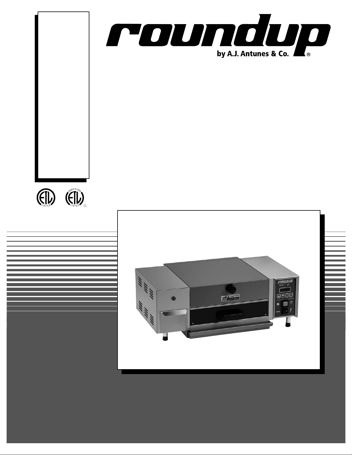
A.J.Antunes roundup MS-355 User manual

MIRACLE STEAMER
Models MS-355
Owner’s Manual
P/N 1010456 Rev. C 08/12
MANUFACTURING
NUMBERS:
9100480
9100482
9100483
9100486
A
S
D
L
I
S
T
E
CM
O
I
N
N
I
T
A
T
C
T
I
S
L
US
E
D
D
L
I
S
T
E
C US
I
N
T
E
R
T
E
K

MIRACLE STEAMER
2P/N 1010456 Rev. C 08/12
A.J. Antunes & Co.
General
The Miracle Steamer produces steam using plain tap
water for quick heating and reconstituting of food items.
Simple push-button action delivers a fully adjustable
impulse of steam. Because the amount of steam is
consistent, it removes the guesswork and produces a
uniform finished product from one operator to the next.
This manual provides the safety, installation, and oper-
ating procedures for the Miracle Steamer. We recom-
mend that all information contained in this manual be
read prior to installing and operating the unit.
Your Miracle Steamer is manufactured from the finest
materials available and assembled to Roundup’s strict
quality standards. This unit has been tested at the fac-
tory to ensure dependable trouble-free operation.
OWNER INFORMATION
TABLE OF CONTENTS
IMPORTANT! Keep these instructions for future reference. If the unit changes
ownership, be sure this manual accompanies the equipment.
Warranty Information
Please read the full text of the Limited Warranty in this
manual.
If the unit arrives damaged, contact the carrier imme-
diately and file a damage claim with them. Save all
packing materials when filing a claim. Freight damage
claims are the responsibility of the purchaser and NOT
covered under warranty.
The warranty does NOT extend to:
• Damagescausedinshipmentordamageas
result of improper use.
• Installationofelectricalservice.
• Normalmaintenanceasoutlinedinthismanual.
• Malfunctionresultingfromimpropermaintenance.
• Damagecausedbyabuseorcarelesshandling.
• Moisturedamagetoelectricalcomponents.
• Damagefromtamperingwith,removalof,or
changing any preset control or safety device.
Owner Information .....................................................2
General......................................................................2
Warranty Information .................................................2
Service/Technical Assistance ....................................3
ModelDesignation.....................................................3
Important Safety Information ....................................3
Specifications .............................................................5
Electrical Ratings.......................................................5
Electrical Cord & Plug Configurations .......................5
Dimensions................................................................5
Installation...................................................................6
Unpacking..................................................................6
Equipment Setup.......................................................6
Electrical ....................................................................7
Plumbing....................................................................7
Operation.....................................................................8
Operating Instructions ..............................................8
Programming .............................................................8
Hi-Limit Reset Button ..............................................10
StatusIndicatorLEDs..............................................10
Fault Codes .............................................................10
Maintenance.............................................................. 11
Daily.........................................................................11
Monthly ....................................................................12
Troubleshooting .......................................................13
Replacement Parts ...................................................15
Wiring Diagrams.......................................................18
Notes..........................................................................19
Limited Warranty ......................................Back Cover

MIRACLE STEAMER
3
P/N 1010456 Rev. C 08/12
A.J. Antunes & Co.
Service/Technical Assistance
If you experience any problems with the installation or
operation of your unit, contact your Authorized Service
Agency. They can be found in the service agency
directory packaged with the equipment.
Fill in the information below and have it handy when
calling your Authorized Service Agency for assistance.
The serial number is on the specification plate located
on the rear of the unit.
Purchased From:
DateofPurchase:
Model No.:
Serial No.:
Mfg. No.:
Refer to the service agency directory and fill in the
information below:
Authorized Service Agency
Name:
Phone No.:
Address:
Use only genuine Roundup replacement parts in this
unit. Use of replacement parts other than those sup-
plied by the manufacturer will void the warranty. Your
Authorized Service Agency has been factory trained
and has a complete supply of parts for this unit.
You may also contact the factory at 1-877-392-7854
or 1-630-784-1000 if you have trouble locating your
Authorized Service Agency.
IMPORTANT
A.J. Antunes & Co. reserves the right to change specifications and product design
without notice. Such revisions do not entitle the buyer to corresponding changes,
improvements, additions, or replacements for previously purchased equipment.
Model Designation
TYPE OF POWER CORD
C = COMMERCIAL
TYPE OF PLUG
V = NEMA 6-20P
F = NEMA 5-15P
MS-355XX
55=Timer/DrawerModel
3 =FrontWaterDrawer
OWNER INFORMATION (continued)

MIRACLE STEAMER
4P/N 1010456 Rev. C 08/12
A.J. Antunes & Co.
In addition to the warnings and cautions in this manual,
use the following guidelines to safely operate the unit.
• Readallinstructionsbeforeusingequipment.
• Foryoursafety,theequipmentisfurnishedwith
aproperlygroundedcordconnector.DoNOT
attempt to defeat the grounded connector.
• Installorlocatetheequipmentonlyforitsintend-
eduseasdescribedinthismanual.DoNOTuse
corrosive chemicals in this equipment.
• DoNOToperatethisequipmentifithasadam-
aged cord or plug, if it is not working properly, or
if it has been damaged or dropped.
• Thisequipmentshouldbeservicedbyqualified
personnel only. Contact the nearest Roundup
Authorized Service Agency for service.
• DoNOTblockorcoveranyopeningsontheunit.
• DoNOTimmersecordorpluginwater.
• Keepcordawayfromheatedsurfaces.
• DoNOTallowcordtohangoveredgeoftableor
counter.
The following warnings and cautions appear
throughout this manual and should be carefully
observed.
• Turnthepoweroff,unplugthepowercord,
and allow the unit to cool down before per-
forming any service or maintenance.
• Theequipmentshouldbegroundedaccord-
ing to local electrical codes to prevent the
possibility of electrical shock. It requires a
grounded receptacle with separate electrical
lines, protected by fuses or a circuit breaker
of the proper rating.
• Allelectricalconnectionsmustbeinaccor-
dance with local electrical codes and any
other applicable codes.
• WARNING ELECTRICAL SHOCK HAZARD.
FAILURE TO FOLLOW THESE INSTRUCTIONS
COULD RESULT IN SERIOUS INJURY OR
DEATH.
- Electrical ground is required on this unit.
- Do NOT modify the power supply cord plug.
If it does not fit the outlet, have a proper
outlet installed by a qualified electrician.
- Do NOT use an extension cord with this
appliance.
- Check with a qualified electrician if you are
unsure if the unit is properly grounded.
• Thisequipmentistobeinstalledtocom-
ply with the basic plumbing code of the
Building Officials and Code Administrators,
Inc. (BOCA) and the Food Service Sanitation
Manual of the Food and Drug Administration
(FDA).
• Ifthesupplycordisdamaged,itmustbe
replaced by the manufacturer, its service
agent, or a similarly qualified person.
• DoNOTcleanthisappliancewithawaterjet.
• DoNOTuseasanitizingsolutionorabrasive
materials. The use of these may cause dam-
age to the stainless steel finish.
• Toensurepropersteamingcharacteristics,
some calcium/mineral deposits must be pres-
ent on the Generator surface. If, during clean-
ing, the surface does become free of calcium/
mineral deposits, one approved method is to
add plain tap water to the surface and allow
it to boil off. This will ensure proper steam-
ing characteristics by creating a thin layer of
deposits on the surface.
• Chlorides or phosphates in cleaning agents
(suchasbleach,sanitizers,degreasers,or
detergents) could cause permanent damage
to stainless steel equipment. The damage is
usually in the form of discoloration, dulling
of metal surface finish, pits, voids, holes, or
cracks. This damage is permanent and not
covered by warranty.
• Thefollowingtipsarerecommendedformain-
tenance of your stainless steel equipment,
- Always use a soft, damp cloth for cleaning,
rinse with clear water, and wipe dry. When
required, always rub in direction of metal
polish lines.
- Routine cleaning should be done daily
using soap, ammonia detergent, and water.
- Stains and spots should be removed using
a vinegar solution.
- Finger marks and smears should be
rubbed off using soap and water.
- Hard water spots should be removed using
a vinegar solution.
IMPORTANT SAFETY INFORMATION (continued)

MIRACLE STEAMER
5
P/N 1010456 Rev. C 08/12
A.J. Antunes & Co.
SPECIFICATIONS
Electrical Ratings Electrical Cord & Plug Configurations
25” (635 mm)
17-1/8” (435 mm)
9-1/2”
(234 mm)
Model and
Mfg. No.
Voltage Watts Amps Hertz
MS-355
9100480
208 3300 15.9 50/60
MS-355
9100482
120 1800 15.0 50/60
MS-355
9100483
120 1800 15.0 50/60
MS-355CV
9100486
230 3300 14.4 50/60
Model and
Mfg. No.
Description Configuration
MS-355CV
9100480
9100486
6-20P, 20 Amp.,
250 VAC.,
Non–locking
(Assembly
Only).
MS-355CF
9100482
5-15P, 15 Amp.,
120 VAC.,
Non-locking
(Assembly
Only).
MS-355
9100483
NEMA 5-20P
20 Amp., 120
Volt
Non-locking
Dimensions
WHT BLK
GRN

MIRACLE STEAMER
6P/N 1010456 Rev. C 08/12
A.J. Antunes & Co.
Unpacking
1. Remove the unit and all packing materials from
the shipping carton.
2. The unit should come with the items listed below:
• Owner’sManual
• AuthorizedServiceAgencyDirectory
• DrawerAssembly
NOTE: If any parts are missing or damaged, con-
tact A.J. Antunes IMMEDIATELY at 1-800-253-2991
or 1-630-784-1000.
3. Remove all packing materials and protective
coverings from the unit.
4. RemoveandwashtheDrawer,DrawerLinerwith
Rollers,andDripPan(Figure1)insoapandwater.
Rinse with clean hot water and allow to air dry.
5. Wipe all surfaces of the unit with a hot, damp
cloth.
NOTE: Do NOT use a dripping wet cloth. Wring
out before use.
6. Re-install all removed parts.
INSTALLATION
Drawer
Drip Pan
Figure 1. Washing Parts
Drawer Liner
with Rollers
Equipment Setup
When placing the unit into service, pay attention to the
following guidelines:
• Makesurepowerisoffandtheunitisatroom
temperature.
• DoNOTblockorcoveranyopeningsontheunit.
• DoNOTimmersecordorpluginwater.
• Keepcordawayfromheatedsurfaces.
• DoNOTallowcordtohangoveredgeoftableor
counter.

MIRACLE STEAMER
7
P/N 1010456 Rev. C 08/12
A.J. Antunes & Co.
THIS UNIT IS DESIGNED TO
OPERATE ON 208 VOLTS
ONLY. APPLICATION WITH ANY
OTHER VOLTAGE SUPPLY
COMPLETELY VOIDS ALL
WARRANTY. PLEASE CHECK
YOUR LINE VOLTAGE BEFORE
INSERTING THIS PLUG INTO THE
RECEPTACLE.
WARNING WARNING
THIS UNIT IS DESIGNED TO
OPERATE ON 120 VOLTS
ONLY. APPLICATION WITH ANY
OTHER VOLTAGE SUPPLY
COMPLETELY VOIDS ALL
WARRANTY. PLEASE CHECK
YOUR LINE VOLTAGE BEFORE
INSERTING THIS PLUG INTO THE
RECEPTACLE.
WARNING WARNING
120 VAC
ONLY
208 VAC
ONLY
THIS APPLIANCE MUST BE
EARTHED (GROUNDED)
THIS APPLIANCE MUST BE
EARTHED (GROUNDED)
THIS APPLIANCE MUST BE
EARTHED (GROUNDED)
THIS APPLIANCE MUST BE
EARTHED (GROUNDED)
THIS UNIT IS DESIGNED TO
OPERATE ON 220-240 VOLTS
ONLY. APPLICATION WITH ANY
OTHER VOLTAGE SUPPLY
COMPLETELY VOIDS ALL
WARRANTY. PLEASE CHECK
YOUR LINE VOLTAGE BEFORE
INSERTING THIS PLUG INTO THE
RECEPTACLE.
WARNING WARNING
220-240
VAC ONLY
THIS APPLIANCE MUST BE
EARTHED (GROUNDED)
THIS APPLIANCE MUST BE
EARTHED (GROUNDED)
CAUTION
All electrical connections must be in accordance
with local electrical codes and any other appli-
cable codes.
Plumbing
NOTE: Miracle Steamer models are designed to
use cold tap water. Distilled water may be used to
reduce calcium/mineral deposit buildup and reduce
maintenance costs.
The MS-355 models have a self-contained water tank.
To fill the self-contained water tank:
1. Open the sliding tank drawer on the side of the
unit (Figure 2).
NOTE: Make sure filter inside tank is installed
properly.
2. Pour in cold tap water. The tank will hold
approximately 3 quarts (2.81 liters).
Do NOT overfill the unit water tank. Only fill the
tank to 90% full.
3. Close the sliding tank drawer.
CAUTION
This equipment is to be installed to comply with
the basic plumbing code of the Building Officials
and Code Administrators, Inc. (BOCA) and the
Food Service Sanitation Manual of the Food and
Drug Administration (FDA).
INSTALLATION (continued)
READY
ADD
WATER
Figure 2. Filling Water Tank
Indicator Light (Low water)
Tank
CAUTION
Be sure to follow all safeguards and precautions
in the Important Safety Instructions section of this
manual.
Electrical
1. Set the unit on a sturdy, level table or work surface.
2. Ensure that the line voltage corresponds to the
stated voltage on the units specification label and
power cord warning tag. If you are unsure of
your Line Voltage, contact an electrician.
3. Connect the unit to the power supply.

MIRACLE STEAMER
8P/N 1010456 Rev. C 08/12
A.J. Antunes & Co.
Programming
CYC (Total Cycle Time) refers to the total pro-
grammed steam time set for the product.
SHO (Shot Interval Time) is the time set between
shots of steam during a complete cycle.
H2O (Steam Shot Time) refers to the water volume
used by the water pump or solenoid valve.
The amount of steam produced by the unit depends on
the amount of water sprayed onto the steam generator.
The generator may flood if the H2O setting is too high.
To prevent flooding, increase the Shot Interval Time
(SHO) to allow more time for generator heat recovery.
Adjustments should be made to both values to deter-
mine the best settings for your cooking needs.
To program the control, refer to Figure 4 and follow the
procedure below:
1. Turn the unit on. The unit displays the factory
programmed Total Cycle Time in minutes and
seconds (Figure 4, Item A).
2. Press and release to change the control from
OPERATION to PROGRAM mode.
3. To change the Total Cycle Time in minutes, press
▲or▼tochangethetime(Figure4,ItemB).
4. Press and release again,andpress▲or
▼tochangetheTotalCycleTimeinseconds
(Figure 4, Item C).
5. To change the SHO factory settings, go to
PROGRAM mode, then press and hold both
▲and▼simultaneouslyfor1-2secondsand
release. “SHO” will be displayed (Figure 4,
ItemD).
UP DOWN PRGM START/STOP
POWER
READY
SINGLE SHOT
Figure 3. Operating Controls
Ready Light
Power
Switch
Operate
Button
Message
Display
Start/Stop
Button
Operating Instructions
1. Turn the power on and allow the unit to preheat
for approximately 20-30 minutes.
NOTE: Do NOT push any button during warmup
time. The flashing green Ready Light indicates that
the unit is NOT warmed up. The green Ready Light
will become steady when the unit is warmed up.
2. PullouttheDrawerandsettheproducttobe
steamedontotheDrawer.
3. PushtheDrawerfullyintothesteamer.
4. Single Shot: Press and release the OPERATE
button, wait 20 seconds for the steam to pen-
etrate the product.
Timed Cycle: Press the START/STOP button to
begin the steaming cycle. The display will count
down to zero and an audio signal will sound at
the end of the steaming cycle.
5. Remove steamed product.
WARNING
Toavoidinjury,becarefulwhenpullingDrawer
out from unit. Be sure to allow steam to escape
before putting hands or face over the steamer.
OPERATION

MIRACLE STEAMER
9
P/N 1010456 Rev. C 08/12
A.J. Antunes & Co.
OPERATION (continued)
6. Press and release andthenpress▲or▼to
change the SHO in seconds (Figure 4, Item E).
7. Press and release againandpress▲or▼to
change the SHO in minutes (Figure 4, Item F).
8. Press and release and “H2O” will be dis-
played (Figure 4, Item G).
9. To change the H2O (Steam Shot time), press and
release the PROGRAM button again to display
thesetting(Figure4,ItemH).Use▲or▼to
increase or decrease the time.
10. Press the START/STOP or OPERATE buttons
to store the changes, exit the PROGRAM Mode,
and initiate the cooking cycle.
NOTE: 120V steamers are factory programmed for
the following recommended settings:
• Total Cycle Time (CYC) = 2 min., 00 secs.
(Range: 3 seconds to 99 minutes 59 seconds)
• Shot Interval Time (SHO) = 00 min., 20 secs.
(Range: 3 seconds to 5 minutes 59 seconds)
• Steam Shot Time (H2O) = 0_80
(Range: 0_10 second to 2_50)
NOTE: 208V and 220-240V steamers are factory pro-
grammed for the following recommended settings:
• Total Cycle Time (CYC) = 15 min., 00 secs.
(Range: 3 seconds to 99 minutes 59 seconds)
• Shot Interval Time (SHO) = 00 min., 20 secs.
(Range: 3 seconds to 5 minutes 59 seconds)
• Steam Shot Time (H2O) = 1_00
(Range: 0_10 second to 2_50)
NOTE: The START/STOP or OPERATE buttons may
be pressed any time during programming to store
the changes and exit the PROGRAM Mode.
NOTE: If a change is not made within 5 seconds
at any time during the programming process, all
changes made up to that point are stored in memory
and the control reverts to the OPERATION Mode.
Figure 4. Control Programming Sequence
UP DOWN PRGM
READY
20
SINGLE SHOT
START/STOP
E. SHO Time in Seconds
UP DOWN PRGM START/STOP
READY
00
SINGLE SHOT
F. SHO Time in Minutes
UP DOWN PRGM START/STOP
READY
1500
SINGLE SHOT
A. Total Cycle Time
UP DOWN PRGM START/STOP
READY
15
SINGLE SHOT
B. Total Cycle Minutes
UP DOWN PRGM START/STOP
READY
H20
SINGLE SHOT
UP DOWN PRGM START/STOP
READY
SINGLE SHOT
G. H2O Cycle H. H2O Setting
UP DOWN PRGM START/STOP
READY
00
SINGLE SHOT
UP DOWN PRGM START/STOP
READY
SHO
SINGLE SHOT
C. Total Cycle Seconds D. SHO Cycle

MIRACLE STEAMER
10 P/N 1010456 Rev. C 08/12
A.J. Antunes & Co.
Hi-Limit Reset Button
A hi-limit thermostat turns off electrical power to the
steam generator if it overheats. To reset this thermo-
stat, allow approximately 45 minutes for the unit to cool
down, remove the black cap, and then press the black
reset button located on the rear of the unit (Figure 5).
If the unit requires continuous resetting, contact your
Authorized Service Agency.
Status Indicator LEDs
The Miracle Steamer’s Control Board has four status
indicatorLEDsdescribedbelow:
Green (Program): When lit, indicates the unit is in
Program mode.
Yellow (Audio):Whenlit,indicates10-15VDCisbeing
supplied to the audio signal. The audio signal sounds
andtheLEDlightsforapproximately3seconds.
Red (Heat): When lit, indicates the Control Board is
callingforheatbysupplying10-15VDCtotheSolid
State Relay. When off, indicates that the unit is
satisfied.
Green (H2O): When lit, indicates that 24 VAC is being
supplied to operate the water pump, This LED is only
lit for approximately 1 second.
Fault Codes
When the programming parameters for Minutes/
Seconds/SHO/H2O have been inadvertently changed
below or above their limits, the unit displays the “ERR”
fault code (Figure 6). If this code appears, clear these
settings using the procedure below:
1. Turn the unit off.
2. Press and hold the PROGRAM and START/
STOP buttons simultaneously.
3. Turn the unit on while holding the appropriate
buttons. Release the buttons when the unit stops
beeping,
4. The display will now register the cycle time.
NOTE: Repeat these steps if the unit still displays
the “ERR” fault code.
NOTE: It is recommended that the SHO and H2O
settingsbeadjustedtotherecommendedsettings
shown in the Programming section of this manual.
OPERATION (continued)
READY
ADD
WATER
Figure 5. Hi-Limit Reset Button
Hi-Limit Reset Button
Power Cord
Cap
UP DOWN PRGM START/STOP
POWER
READY
SINGLE SHOT
ERR
Figure 6. “ERR” Fault Code

MIRACLE STEAMER
11
P/N 1010456 Rev. C 08/12
A.J. Antunes & Co.
Daily
1. Turn the power off, unplug the power cord, and
allow the unit to cool down before proceeding.
3. RemovetheDrawer,DrawerLinerwithRollers,
DripPan,TopCover,andSteamVent(Figure7).
4. Wash items in hot, soapy water and then rinse
and wipe dry.
5. Wipe down the food compartment and the entire
exterior of the unit with a clean, hot, damp cloth
(not dripping wet) and wipe dry.
6. Reinstall the Steam Vent first, followed by the
remaining items.
NOTE: Frequency of cleaning is determined by
water conditions, usage and water filtration
systems.
NOTE: Failure to properly clean and dry the above
mentioned items prior to reassembly may result in
the accumulation of water/moisture overnight. This
may lead to permanent damage of the equipment’s
finish and its accessories. This damage is not
covered by warranty.
MAINTENANCE
WARNING
Turn the power off, unplug the power cord, and
allow the unit to cool down before performing any
service or maintenance.
CAUTION
Chlorides or phosphates in cleaning agents (such
asbleach,sanitizers,degreasers,ordetergents)
could cause permanent damage to stainless steel
equipment. The damage is usually in the form of
discoloration, dulling of metal surface finish, pits,
voids, holes, or cracks. This damage is perma-
nent and not covered by warranty. The following
tips are recommended for maintenance of your
stainless steel equipment:
• Always use a soft, damp cloth for cleaning,
rinse with clear water, and wipe dry. When
required, always rub in direction of metal polish
lines.
• Routinecleaningshouldbedonedailyusing
soap, ammonia detergent, and water.
• Stainsandspotsshouldberemovedusinga
vinegar solution.
• Fingermarksandsmearsshouldberubbedoff
using soap and water.
• Hardwaterspotsshouldberemovedusinga
vinegar solution.
CAUTION
DoNOTuseasanitizingsolutionorabrasive
materials. The use of these may cause damage to
the stainless steel finish.
CAUTION
If a chemical cleaner is used, be sure it is safe to
use on cast aluminum. Observe all precautions
and warnings on product label.
Figure 7. Daily Cleaning
Drip Pan
Drawer Liner
with Rollers
Drawer
Top Cover Steam Vent

MIRACLE STEAMER
12 P/N 1010456 Rev. C 08/12
A.J. Antunes & Co.
NOTE: If deposits are still excessive and/or diffi-
cult to remove, refer to Steps 6 and 11.
6. Pour delimer solution (not supplied) onto the
Generator surface. Follow the delimer manufac-
turer’s instructions for proper mixture and use.
7. Using a sponge or a dry towel, remove the
delimer solution from the Generator surface, then
rinse with clean water.
Monthly
The Miracle Steamer utilizes an open steam generator.
Water sprayed onto the Generator surface flashes into
steam immediately, but the minerals in the water do not
steam, they stay on the Generator surface. A small
amount of calcium/mineral deposits are needed for
proper operation, but a buildup of excessive calcium/
mineral deposits causes poor steaming efficiency,
excessive moisture (wet steam) and will eventually
severely hinder the steaming action.
1. Turn the power off, unplug the power cord, and
allow the unit to cool down.
2. PerformtheDailycleaning,butdoNOTreas-
semble the unit.
3. Remove the Wing Nut, Generator Cover, and
Diffuser(Figure8).Washtheseitemsinhot,
soapy water, rinse and WIPE DRY.
4. With the unit cool, use a wire brush and/or
scraper to loosen and remove the excessive
calcium/mineral deposits from the Generator
surface (Figure 8).
5. Take a wire brush and clean out any buildup from
the 28 Steam Ports (26 vertical and 2 horizontal)
of the Generator (Figure 8). Remove the loose
buildup, wipe the Generator with a clean, damp
cloth, and reassemble the unit.
CAUTION
If a chemical cleaner/delimer is used, be sure it is
safe to use on cast aluminum. Observe all pre-
cautions and warnings on the product label.
MAINTENANCE (continued)
NOTE: To ensure proper steaming characteristics,
some calcium/mineral deposits must be present on
the Generator surface. If, during cleaning, the sur-
face does become free of calcium/mineral deposits,
add plain tap water to the surface and allow it to
boil off. If necessary, repeat this process to formu-
late a thin coating of calcium/mineral deposits.
NOTE: In soft water areas, it may be necessary
to add a small amount of lime to the Generator to
“season” it. This will ensure proper steaming char-
acteristics by producing a thin coating of calcium/
mineral deposits on the Generator surface.
Seasoning mixture consists of 3/4 ounces (25ml/
25cc) baking soda, 3/4 ounces (25ml/25cc) lime
mixed with 1 quart (950ml/950cc) of water. Stir
mixture and pour 1/4” deep onto the hot Generator
surface. After mixture is converted to steam, the
remaining loose power can be removed.
8. Plug the power cord into the appropriate outlet.
9. Turn the power on and allow the unit to warm up
for approximately 30 minutes.
10. Push and release the OPERATE button or the
START/STOP button several times to operate the
steamer. This purges any remaining delimer
residue from the Generator surface.
11. Turn the power off, reinstall all parts and accesso-
ries, and return the unit to service.
READY
ADD
WATER
Diffuser
Wing Nut
Generator
Cover
Generator
Steam Ports
(26 vertical and
2horizontal)
Figure 8. Monthly Cleaning

MIRACLE STEAMER
13
P/N 1010456 Rev. C 08/12
A.J. Antunes & Co.
TROUBLESHOOTING
WARNING
Toavoidpossiblepersonalinjuryand/ordamagetotheunit,inspection,testandrepairofelectricalequip-
ment should be performed by qualified service personnel. The unit should be unplugged when servicing,
except when electrical tests are required.
Problem Possible Cause Corrective Action
ControlDisplayisblank(powerison
but indicator light is off).
The power cord is not correctly
plugged in.
Plug the power cord into the appro-
priate outlet.
The power cord and/or electrical
plug is damaged.
Inspect electrical wire, plug, and
receptacle.
The main electrical panel circuit
breaker is off or has been tripped.
Reset circuit breaker. Contact your
maintenance person or Authorized
Service Agency if it trips again.
Switch is inoperable. Contact your maintenance person or
Authorized Service Agency for
service.
ControlDisplayisblank(powerison
and indicator light is on).
Control Board is inoperable Contact your maintenance person or
Authorized Service Agency for
service.
Transformer is inoperable.
Loose, burnt, or broken wires in
circuit.
Unit does not heat up (Control
Displayison).
Hi-Limit Thermostat is tripped or
inoperable.
Reset the Hi-Limit Thermostat
according to the Operations sec-
tion of this manual. If the Hi-Limit
Thermostat requires continuous
resetting, contact your Authorized
Service Agency for service.
Solid State Relay is inoperable.
Thermocouple is inoperable.
Control Board is inoperable.
Steam Generator is inoperable.
Loose, burnt, or broken wires in
circuit.
The unit’s main electrical panel
circuit breaker trips.
Damagedreceptacle,plug,orcord;
alooseconnection;oraninternal
component failure.
Turn the unit off, allow it to cool to
room temperature, and then restart.
Contact your maintenance person
or Authorized Service Agency if the
condition repeats.
Water leaking inside electrical
housing.
Pinhole leak in rubber hoses. Replace hoses.
Loose or damaged water line tubes
and/or fittings inside electrical
housing.
Tighten or replace tubes and/or
fittings.
“ERR” appears in the Control
Display.
Programming and/or SHO and
H2O values were adjusted/changed
improperly.
Reset the Control Board as
described in the Programming sec-
tion of this manual. See Fault Codes.

MIRACLE STEAMER
14 P/N 1010456 Rev. C 08/12
A.J. Antunes & Co.
Problem Possible Cause Corrective Action
Unit heats but there
is little or no steam
produced
and/or
The product requires
more steaming than
usual.
Filter Strainer is restricted. Check and clean the Filter Strainer as described in
the Maintenance section of this manual.
Unit is not being cleaned properly
(daily/monthly).
Clean unit daily and monthly as described in the
Maintenance section of this manual.
Programming and/or SHO, H2O
values were adjusted/changed
improperly.
Reprogram the SHO and H2O values as described
in the Programming section of this manual.
Insufficient or excessive calcium/
mineral deposits on the Generator
surface.
Verify a thin layer of calcium/mineral deposits is
present on the Generator surface. Refer to the
Maintenance section of this manual.
Generator surface is bare. Generator surface must have a thin calcium/min-
eral coating for proper steaming. Refer to the
Maintenance section of this manual.
Generator Steam Ports are
restricted.
Clean the Steam Ports as described in the
Maintenance section of this manual.
Generator Cover is warped or loose. Verify that the Generator Cover’s Wing Nut is tight.
If noticeable steam escapes around the Generator
Cover, replace the cover.
GeneratorDiffuserismissing. InstallGeneratorDiffuserorreplaceifmissing.
Generator surface temperature is too
low.
Verify Generator surface temperature to be 380–
420°F (193–215°C).
Excessive con-
densation in Food
Compartment.
Programming and/or SHO and H2O
values were adjusted improperly.
Reprogram the SHO and H2O values as described
in the Programming section of this manual.
Steam coming out
around top covers or
sides.
Generator Cover’s Wing Nut is
loose.
Tighten Wing Nut.
Generator Cover is warped. Replace Generator Cover.
TROUBLESHOOTING (continued)

MIRACLE STEAMER
15
P/N 1010456 Rev. C 08/12
A.J. Antunes & Co.
REPLACEMENT PARTS
READY
ADD
WATER
53
27
26
46
46
46
10
19
74
75
77
76
73
2
111
18
52
16
55
56
9
8
65
64
69
65
69
72
68
67
66
70
71
61
7
4
3
6
13
25
30
82

MIRACLE STEAMER
16 P/N 1010456 Rev. C 08/12
A.J. Antunes & Co.
49
49
READY
32
48
42
57
50
51
45
44 62
58
47
43
28
47
READY
ADD
WATER
59
51
78
79
38
38
41
41
36
37
33
29 47
ADD
WATER
63
39
78
17
20
34
54 51
14
81
22
40
40
60
23
15
12
35
83
REPLACEMENT PARTS (continued)

MIRACLE STEAMER
17
P/N 1010456 Rev. C 08/12
A.J. Antunes & Co.
1 0011314 Steam Vent Assy. 1
2 7000237 Top Cover Assy. (Incl. #73-77) 1
3 0011413 Liner Assy. (Incl. #65, 69, 72) 1
4 0011471 DrawerAssy.(Incl.#64-71) 1
6 040P138 Locknut, Conduit, 1/2” 1
7 040K251 StrainRelief(includes#6) 1
8 0503441 Cover, Access 1
9 0503536 DripPan,Water 1
10 0503712 Cover, Tank Housing 1
11 0700452 Power Cord, NEMA 6-20P 250v 1
Mfg. No. 9100480 & 486
0700463 Power Cord, 5-15P 120V 1
Mfg. No. 9100482
0700451 NEMA 5-20P 20 Amp., 1
120 Volt Non-locking
Mfg. No. 9100483
12 7000652 Relay 1
13 1001066 Label,WiringDiagram 1
14 7000317 Control Board, 24V, 50/60 Hz 1
15 4050180 Heat Sink 1
16 0011370 Leg Assy., 2” 4
17 0021241 Channel Weldment 1
18 0021242 Floor/Chassis Weldment 1
19 7000245 Generator, 208V 1
7000246 Generator, 230V 1
7000300 Generator, 120V 1
20 0011447 Float Switch Assy. 1
21 0300129 Stud, Cover 1
22 040P119 Bushing, Shorty, 3/8” 4
23 0500281 Bracket, Pump Mounting 2
24 05P2199 Spacer 2
26 0503431 Diffuser 1
27 0503433 Cover, Generator 1
28 0503435 Retainer, Thermocouple 1
29 0503472 Bracket, Hi-Limit Thermostat Support 1
30 0503713 Guard, Wire 1
31 0700600 Wire Set Float Switch (not shown) 1
32 1001036 Label, Control Panel 1
33 2000203 Tube, Restrictor, 1/4” 1
34 2000208 Tube, Supply 1
35 2040106 Adapter, Tube/Hose 1
36 2040145 Elbow, Female, 1/8” x 1/4” 1
37 2040146 Tee, Female, 1/8” x 1/4” 1
38 211P101 Clamp, Hose, 3/8” 2
39 211P103 Clamp, Hose, 1/2” 2
40 218P112* Nut, Nylon, 1/2-13 2
41 7000446 Pipe, 3-5/8” Long 2
Item Part No. Description Qty.
42 300P102* Nut, Speed, “U”, #8-32 2
43 304P105* Nut,Hex,KEPS,#4-40,Zinc 4
44 306P101* Nut, Hex, #6-32 2
45 306P123* Screw, Machine, #6-32 x 7/8” 2
46 306P134* Screw, Machine, #6-32 x 3/8” 3
47 308P103* Screw, Machine, #8-32 x 1/4” 20
48 308P105* Screw, Machine, #8-32 x 1/2” 4
49 308P120* Screw, Machine, #8-32 x 5/8” 2
50 308P124* Screw, Machine, 1
One-Way, #8-32 x 1/2”
51 308P143* Nut,Hex,KEPS,#8-32 8
52 310P110* Screw, Machine, #10-32 x 1/2”, SS 4
53 325P170* Wing Nut, 1/4-20 1
54 0500229 Retainer 1
55 7000542 Switch, Rocker 250V 1
7000543 Switch, Rocker 120V 1
56 4010166 Momentary Switch (Green) 1
4010190 Momentary Switch (White) 1
57 7000319 Transformer, 115-230/24V 1
58 7000135 Thermostat, Hi-Limit 1
59 4040144 Water Pump, Oscillating, 24V 1
60 4050214 Thermocouple,Type-K 1
61 406P107* Cable Tie, 1/8” Wide x 5” Long 3
62 7000136 Terminal Block, 3-Pole 1
63 4060371 Indicator Light, Blue, 12V 1
64 0021283 DrawerWeldment 1
65 210K195 Bearing,Roller,Nylon,SS 4
(includes #69)
66 2100257 Handle 1
67 2100264 Guard, Handle 1
68 325P132* Screw, Machine, 1/4-20 x 1/2” 2
69 05P2291 Spacer 2
70 306P137* Stud, PEM, #6-32 x 3/8” 2
71 306P107* Acorn Nut, #6-32 2
72 0021237 Liner Weldment 1
73 0503686 Cover, Top 1
74 2100273 Knob 1
75 2100249 Guard,Knob 1
76 390P101* Bolt, M8 x 1.25 x 14mm Long 1
77 100P864 Label, Caution HOT 1
78 0011446 Silicone Tube Assy., 26” 1
79 0021358 Silicone Tube Assy., 17” 1
81 0011415 Water Tank Assembly 1
82 210K108 Foot,Rubber(4Pack) 1
83 7000693 WaterFittingKit 1
(Incl. #33, 35, 36, 37)
* Only available in quantities of 10.
Item Part No. Description Qty.
REPLACEMENT PARTS (continued)

MIRACLE STEAMER
18 P/N 1010456 Rev. C 08/12
A.J. Antunes & Co.
WIRING DIAGRAMS
*NOTE: For 208-240 VAC units, the two primary coils are wired in series with one another.
For 120 VAC units, the two primary coils are wired in parallel with one another.

MIRACLE STEAMER
19
P/N 1010456 Rev. C 08/12
A.J. Antunes & Co.
NOTES

LIMITED WARRANTY
EquipmentmanufacturedbyRoundupFoodEquipmentDivisionofA.J.Antunes&Co.hasbeencon-
structed of the finest materials available and manufactured to high quality standards. These units are
warranted to be free from electrical and mechanical defects for a period of one (1) year from date of
purchase under normal use and service, and when installed in accordance with manufacturer’s recom-
mendations. To insure continued operation of the units, follow the maintenance procedures outlined in
theOwner’sManual.Duringthefirst12months,electro-mechanicalparts,non-overtimelabor,andtrav-
el expenses up to 2 hours (100 miles/160 km), round trip from the nearest Authorized Service Center
are covered.
1.This warranty does not cover cost of installation, defects caused by improper storage or handling prior to
placing of the Equipment. This warranty does not cover overtime charges or work done by unauthorized
service agencies or personnel. This warranty does not cover normal maintenance, calibration, or regular
adjustments as specified in operating and maintenance instructions of this manual, and/or labor involved
in moving adjacent objects to gain access to the equipment. This warranty does not cover consumable/
wear items. This warranty does not cover damage to the Load Cell or Load Cell Assembly due to abuse,
misuse, dropping of unit/shock loads or exceeding maximum weight capacity (4 lbs). This warranty does
not cover water contamination problems such as foreign material in water lines or inside solenoid valves.
It does not cover water pressure problems or failures resulting from improper/incorrect voltage supply.
This warranty does not cover Travel Time & Mileage in excess of 2 hours (100 miles/160 km) round trip
from the nearest authorized service agency.
2.Roundup reserves the right to make changes in design or add any improvements on any product. The
right is always reserved to modify equipment because of factors beyond our control and government
regulations. Changes to update equipment do not constitute a warranty charge.
3.
If shipment is damaged in transit, the purchaser should make a claim directly upon the carrier. Careful inspec-
tion should be made of the shipment as soon as it arrives and visible damage should be noted upon the car-
rier’sreceipt.Damageshouldbereportedtothecarrier.Thisdamageisnotcoveredunderthiswarranty.
4.Warranty charges do not include freight or foreign, excise, municipal or other sales or use taxes. All such
freight and taxes are the responsibility of the purchaser.
5.THIS WARRANTY IS EXCLUSIVE AND IS IN LIEU OF ALL OTHER WARRANTIES, EXPRESSED
OR IMPLIED, INCLUDINGANY IMPLIED WARRANTY OR MERCHANTABILITY OR FITNESS FOR
APARTICULARPURPOSE,EACHOFWHICHISHEREBYEXPRESSLYDISCLAIMED.THEREM-
EDIES DESCRIBEDABOVEARE EXCLUSIVE AND IN NO EVENT SHALL ROUNDUP BE LIABLE
FOR SPECIAL CONSEQUENTIAL OR INCIDENTAL DAMAGES FOR THE BREACH OR DELAY IN
PERFORMANCE OF THIS WARRANTY.
This manual suits for next models
4
Table of contents
Other A.J.Antunes Kitchen Appliance manuals