A-Neuvideo EP-132 User manual

AUDIO / VIDEO MANUFACTURER
EP-132
Serial To Ethernet Converter
V2.0
INSTRUCTION MANUAL
A-NeuVideo.com
Frisco, Texas 75034
(317) 456-2461

SAFETY INFORMATION
1. To ensure the best results from this product, please read this manual and all other documentation before operating your equipment.
Retain all documentation for future reference.
2. Follow all instructions printed on unit chassis for proper operation.
3. To reduce the risk of re, do not spill water or other liquids into or on the unit, or operate the unit while standing in liquid.
4. Make sure power outlets conform to the power requirements listed on the back of the unit. Keep unit protected from rain, water and
excessive moisture.
5. Do not attempt to clean the unit with chemical solvents or aerosol cleaners, as this may damage the unit. Dust with a clean dry cloth.
6. Do not use the unit if the electrical power cord is frayed or broken. The power supply cords should be routed so that they are not
likely to be walked on or pinched by items placed upon or against them, paying particular attention to cords and plugs, convenience
receptacles, and the point where they exit from the appliance.
7. Do not force switched or external connections in any way. They should all connect easily, without needing to be forced.
8. Always operate the unit with the AC ground wire connected to the electrical system ground. Precautions should be taken so that the
means of grounding of a piece of equipment is not defeated.
9. AC voltage must be correct and the same as that printed on the rear of the unit. Damage caused by connection to improper AC
voltage is not covered by any warranty.
10. Turn power off and disconnect unit from AC current before making connections.
11. Never hold a power switch in the “ON” position.
12. This unit should be installed in a cool dry place, away from sources of excessive heat, vibration, dust, moisture and cold. Do not use
the unit near stoves, heat registers, radiators, or other heat producing devices.
13. Do not block fan intake or exhaust ports. Do not operate equipment on a surface or in an environment which may impede the normal
ow of air around the unit, such as a bed, rug, carpet, or completely enclosed rack. If the unit is used in an extremely dusty or smoky
environment, the unit should be periodically “blown free” of foreign dust and matter.
14. To reduce the risk of electric shock, do not remove the cover. There are no user serviceable parts inside. Refer all servicing to
qualied service personnel. There are no user serviceable parts inside.
15. When moving the unit, disconnect input ports rst, then remove the power cable; nally, disconnect the interconnecting cables to
other devices.
16. Do not drive the inputs with a signal level greater than that required to drive equipment to full output.
17. The equipment power cord should be unplugged from the outlet when left unused for a long period of time.
18. Save the carton and packing material even if the equipment has arrived in good condition. Should you ever need to ship the unit,
use only the original factory packing.
19. Service Information Equipment should be serviced by qualier service personnel when:
A. The power supply cord or the plug has been damaged.
B. Objects have fallen, or liquid has been spilled into the equipment.
C. The equipment has been exposed to rain
D. The equipment does not appear to operate normally, or exhibits a marked change in performance
E. The equipment has been dropped, or the enclosure damaged.
THIS SAFETY INFORMATION IS OF A GENERAL NATURE AND MAY BE SUPERSEDED BY INSTRUCTIONS CONTAINED WITHIN THIS MANUAL

TABLE OF CONTENTS
ANEUVIDEO
1
CONTENTS
INTRODUCTION & PACKAGE CONTENTS ...............................1
BLOCK DIAGRAM / DOWNLOAD LINKS .....................................2
FEATURES & SPECIFICATIONS .................................................3
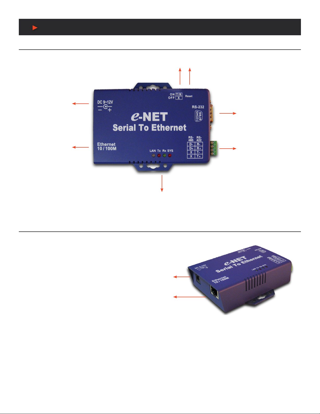
CONVERTER DESCRIPTION ......................................................4
WIRING ARCHITECTURE ...........................................................6
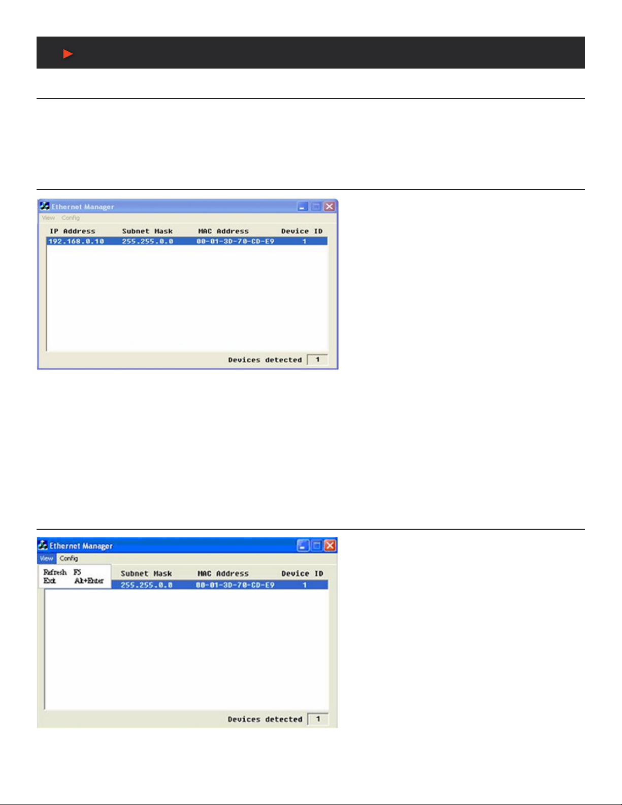
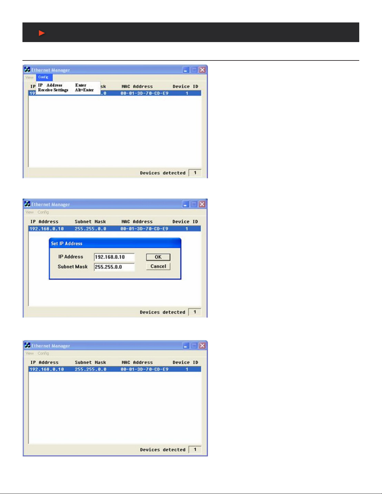
CONVERTER CONFIGURATION ................................................7
WEB CONSOLE CONFIGURATION .............................................9
SELF-TESTING ...........................................................................13
APPENDIX - PIN OUTS & CABLE WIRING .................................16
Dear Customer
Thank you for purchasing this product. For optimum performance
and safety, please read these instructions carefully before
connecting, operating or adjusting this product. Please keep this
manual for future reference.
INTRODUCTION
EP-132 TCP/IP converter is designed to make your serial devices
Internet ready instantly. EP-132 Series of GDI2000 TCP/IP
converter makes the ideal choice for connecting your RS-232 or
RS-422/485 serial devices—such as PLCs, meters and sensors
to IP-based Ethernet LAN, making possible for your software to
access serial devices anywhere and anytime over local LAN or the
Internet.
EP-132 Series converter ensures the compatibility of network
software that uses standard network API (Winsock or BSD Sockets)
by providing TCP Server Mode, TCP Client Mode and UDP Mode.
EP-132 Series Virtual COM driver, software that works with COM
port can be set up to work over TCP/IP network in no time. This
excellent feature preserves your software investment and lets you
enjoy the benets of networking your serial devices instantly.
EP-132 Series converter supports manual conguration via the
handy web browser console and many protocols including TCP, IP,
UDP, HTTP, DHCP, ICMP and ARP. It is the best solution to network
your serial devices.
PACKAGE CONTENTS
Before attempting to use this unit, please check the packaging and
make sure the following items are contained in the shipping carton:
• EP-132 Converter
• Power Adaptor (9VDC 500mA) North American Plug
SAFETY PRECAUTIONS
Please read all instructions before attempting to unpack, install or
operate this equipment and before connecting the power supply.
Please keep the following in mind as you unpack and install this
equipment:
• Always follow basic safety precautions to reduce the risk of re,
electrical shock and injury to persons.
• To prevent re or shock hazard, do not expose the unit to rain,
moisture or install this product near water.
• Never spill liquid of any kind on or into this product.
• Never push an object of any kind into this product through any
openings or empty slots in the unit, as you may damage parts
inside the unit.
• Do not attach the power supply cabling to building surfaces.
• Use only the supplied power supply unit (PSU). Do not use the
PSU if it is damaged.
• Do not allow anything to rest on the power cabling or allow any
weight to be placed upon it or any person walk on it.
• To protect the unit from overheating, do not block any vents or
openings in the unit housing that provide ventilation and allow for
sufcient space for air to circulate around the unit.
DISCLAIMERS
The information in this manual has been carefully checked and
is believed to be accurate. We assume no responsibility for any
infringements of patents or other rights of third parties which may
result from its use.
We assume no responsibility for any inaccuracies that may be
contained in this document. We make no commitment to update or
to keep current the information contained in this document.
We reserve the right to make improvements to this document and/
or product at any time and without notice.
COPYRIGHT NOTICE
No part of this document may be reproduced, transmitted,
transcribed, stored in a retrieval system, or any of its part translated
into any language or computer le, in any form or by any means
— electronic, mechanical, magnetic, optical, chemical, manual, or
otherwise — without the express written permission and consent.
© Copyright 2015. All Rights Reserved.
Version 2.0 JUNE 2015
TRADEMARK ACKNOWLEDGMENTS
All products or service names mentioned in this document may be
trademarks of the companies with which they are associated.

2
BLOCK DIAGRAM / DOWNLOAD LINKS
BLOCK DIAGRAM
Low-cost devices usually are equipped with low speed processors and limited memories. In reality, they are neither having capability
nor practicality to manage complicated network TCP/IP protocols. EP-132 Series is low cost while providing high performance network
solution by converting data stream between network TCP/IP and popular serial port signals. In stead of processing TCP/IP packets
directly, devices need only deal with those interface signals, which greatly simplies the complexity of TCP/IP network in linkage.
DIRECT DOWNLOAD LINKS
DEMO SOURCE CODE ZIP File (10MB):
http://www.a-neuvideo.com/shop/download/E-P132/Demo_Source_Code.zip
IP SEARCH UTILITY ZIP File (412KB):
http://www.a-neuvideo.com/shop/download/E-P132/IP-Search_Utility.zip
SERIAL-TO-ETHERNET QUICK START GUIDE PDF (260KB):
http://www.a-neuvideo.com/shop/download/E-P132/Serial-to-Ethernet_QS_guide.pdf
TECHNICAL MANUALS ZIP FILE (1.12MB):
http://www.a-neuvideo.com/shop/download/E-P132/Technical_Manuals.zip
COM PORT API COMMAND PDF (65KB):
http://www.a-neuvideo.com/shop/download/E-P132/D.%20Com%20Port%20API%20Command/Console%20Command.pdf
IRTUAL COM ZIP FILE (1.65MB):
http://www.a-neuvideo.com/shop/download/E-P132/Virtual-Com.zip
Or visit the product page on our website to download directly. www.a-neuvideo.com
ANEUVIDEO

3
FEATURES & SPECIFICATIONS
FEATURES
• Data Conversion between RS-232/422/485 and Ethernet: Convert serial device (RS-232, RS-422, RS-485) data/signal into TCP/
IP packet data/signal and send them out with Ethernet data stream or convert the TCP/IP packet data/signal into serial device
data/signal.
• Dynamic IP Conguration: Support DHCP client mode, simplifying network address conguration and management.
• Dual LAN Speed: Support 10/100 Mbps Ethernet, auto-detected.
• Server/Client Dual Modes: EP-132 Series can be congured as network server or network client. In client mode, it can be installed
in network which protected by NAT router or rewall, without the need of a real IP address.
• Web-based Setup: Parameters setup based on HTTP protocol by using standard browsers (IE and Netscape). No special software
would be required.
• Built-in Security Control: Protected setup the password to prevent intruders.
• Firmware Remote Update: Firmware can be updated directly via Ethernet network to keep up with latest network standards.
SPECIFICATIONS
• CPU: 32-bits EP-132 CPU, 25 MHz
• RAM: 2MB SDRAM (1M x16Bits)
• ROM: 128KB Flash ROM
• Ethernet:
• Port Type: RJ-45 Connector
• Speed: 10/100Mbps (Auto Detecting)
• Protocol: ARP, IP, ICMP, UDP, TCP, HTTP, DHCP
• Mode: TCP Server ,TCP Client , UDP
• Setup: HTTP Browser Setup (IE & Netscape), RS-232 Console
• Security: Setup Password
• Protection: Built-in 1.5KV Magnetic Isolation
• Serial Port
• No. of Ports: 1x RS-232 / 1x RS-422/RS-485
• Speed: 300 bps~230.4 Kbps
• Parity: None, Odd, Even, Mark, Space
• Data Bit: 5, 6, 7, 8
• Stop Bit: 1, 2
• RS-232 Signals: Rx, Tx, GND, RTS, CTS, DTR, DSR, DCD
• RS-422 Signals: Rx+, Rx-, Tx+, Tx- (Surge Protection)
• RS-485 Signals: Data+, Data- (Surge Protection)
• Built-in RS-422/RS-485 Terminal Resistor
• 15KV ESD for all signal
• Watch Dog Function
• Power: DC9–12V, 500mA
• LED Lamp: SYS (PWR), LAN, Rx, Tx
• Environment: Operating Temperature: 32°F~122°F (0°C~50°C) / Storage Temperature: 14°F~158°F (-10°C~70°C)
• Dimensions (WxDxH): 4.3 x 3.5 x 1.2 in (110x90x30mm)
• Weight: 5 oz (146 grams)
As product improvements are continuous, specications are subject to change without notice.
ANEUVIDEO

4
Converter Description
Product Panel View
LEFT SIDE
Power Supply
The EP-132 TCP/IP converter is powered by a single
9~12V DC (inner positive/outer negative) power supply
and 500mA of current. A suitable power supply adapter
part of the packaging. Connect power line to power outlet
at left side of EP-132 TCP/IP converter and put adapter
into socket. If power is properly supplied, the “SYS” red
color LED will be blinks each time in one second.
LAN Port
The connector is for network usual RJ45. Simply connect
to your network switch or Hub. When connection made,
the LAN LED indicator will light. When data trafc occurs
on the network, red Tx & Rx LED indicator will blink during
data transferring and receiving.
ANEUVIDEO
DC-IN
POWER
OUTLET
LAN
RESET
BUTTON
RS-422 / 485
TERMINATOR
SERIAL
PORT
RS-232
SERIAL
PORT
RS-485/RS-422
LED
INDICATORS
DC-IN
POWER
OUTLET
LAN

5
Converter Description
RIGHT SIDE
Serial Port of RS-232/RS-422/RS-485
Connect serial data cable between the converter and
serial device. Follow the setup procedure to congure
the parameters of the converter. (See the following
chapters)
LED INDICATORS
SYS “Red LED”: Power indicated (When power on, LED will ash each time in
one second.)
Rx “Green LED”: Network signal receiving indicated (When receive any signal
form network LED will ash.)
Tx “Red LED”: Network signal transforming indicated (When transmit any signal
to network LED will ash.)
LAN “LED”: On-line indicated (When converter link to LAN then the LED will keep
on.) 100M- Green LED/10M- Red LED
Terminator & Reset button
Reset Button
Press the button then turn on the power and wait for 3
seconds. Converter will reset to factory default.
Terminator
There terminator resistor is built-in. If switch 1 & 2 are
set in “ON” position, 120 Ohm resistor will be connected
between the signals.
ANEUVIDEO
RS-232
RS-422 / 485
TERMINATOR
RESET BUTTON

6
Wiring Architecture
RS-232 Wiring Architecture
RS-232 Wiring
Serial Device Converter
RX TX
TX RX -------------------------- HUB --------------------------
GND GND
RS-232 (RTS/CTS) Wiring
Serial Device Converter
RX TX
TX RX
GND --------------------------------- GND -------------------------- HUB --------------------------
RTS CTS
CTS RTS
RS-232 (RTS/CTS, DSR / DTR) Wiring
Serial Device Converter
RX TX
TX RX
GND GND -------------------------- HUB --------------------------
RTS --------------------------------- CTS
CTS RTS
DTR DSR
DSR DTR
RS-422 / RS485 Wiring Architecture
RS-422 Wiring
Serial Device Converter
T + R +
T - R - -------------------------- HUB --------------------------
R + T +
R - T -
RS-485 Wiring
Serial Device Converter
D + D +
D - D - -------------------------- HUB --------------------------
When you nish the steps mentioned above and LED indicators as shown, the converter installed correctly. You can use the Setup Tool
“ETM.exe” to setup IP Address.
For setup proceed the advanced parameters, please use web browser (IE or Netscape) to continue the detailed settings.
ANEUVIDEO

7
Converter Configuration
Initial IP Configuration
When setting up your converter for rst time, the rst thing you should do congure the IP address. This chapter introduces of method to
congure the device server IP address. For more details about network settings, see “Web Console Conguration” in next sub section.
For quick setup of converter, we suggest you reference the “Quick Installation Guide.”
Device Management Utility of ETM
On PC we provide Device Management Utility named
ETM.exe which an executable program in Windows 32 bit
environments. ETM Setup Tool used to detect and setup
the installed converters. It uses UDP broadcast packets
to query and congure converters on the network.
When you activate the tool, it will detect the existence
of installed converters and depict the converters status
such as IP address, Subnet Mask, MAC Address and
Device ID (see Figure 3.1).
If your computer OS is Windows XP version which means
“WINDOWS Firewall” function in OS activated. However
ETM.exe wouldn’t detect the converter IP address,
therefore, you have to temperately disable “WINDOWS
Firewall” function. After nishing the parameters settings,
you can restart “WINDOWS Firewall” function.
Due to nature of broadcast UDP packets, ETM has following characteristics:
• Broadcast packets aren’t limited by subnet. If even IP address of converters and computer running ETM do not belong to same
subnet, it still works ne.
• Broadcast packets can not pass routers. ETM can only be used to monitor devices with computer running ETM in same segment
of local area network.
Menu “View”
• View -> Refresh F5: Refresh the status. ETM will
send another query to get updated information. (See the
Figure 3.2.)
Note: Always run the “View-> Refresh” after any data
change.
• View -> Exit Alt+F4: Exit from the program (see Figure 3.2).
ANEUVIDEO
(Figure 3.1)
(Figure 3.2)

8
Converter Configuration
Menu “Config”
• Cong-> IP Address: (see Figure 3.3)
• Press ENTER or select [IP Address] in the [Cong]
menu, a dialog will be shown (see Figure 3.4).
Note: Because ETM uses broadcast UDP packets for
sake of security, it allows conguration only when
setup the device password is empty.
Assign IP Address with same Subnet Mask of your
computer, avoiding any IP conict with other network
devices.
• When you press [Ok] button, IP address will be
refreshed in 2~3 seconds. (See the Figure 3.5.)
ANEUVIDEO
(Figure 3.3)
(Figure 3.4)
(Figure 3.5)

9
Web Console Configuration
In addition of basic IP address and subnet mask, specic device settings can be set through HTTP protocol with popular browsers, e.g.
Internet Explorer, Netscape, etc. Setup converter as easy as surng on WWW, no special software will be required. Press [Alt] + [Enter]
orselect[DeviceSettings]inthe[Cong]menuwillopenanewwindowinbrowsertologinthedevice. Alternatively, if IP address
of converter already known, you can connect to converter directly by providing IP address in URL eld of browser.
Controller Status
The Login Page
For Setup of EP132 TCP/IP converter as easy as surng on
WWW, no special software will be required. Popular Browsers
such as IE or Netscape can easily do the setup process. In the
browser URL eld, set IP address of device directly, to enter
“Controller Status” page, please follow the steps below.
• Open your browser. This chapter will use IE as example.
• In browser URL eld, type IP address of converter directly
and press ENTER. (The IP address what you set using
Device Management Utility.)
• The “Controller Status” page will be shown (see Figure 3.6).
Field Description
• System time elapsed: The time elapsed since start in this device [Day Hour: Minute: Second] format. This information can be useful
identifying reliability of system.
• Firmware version: Converter rmware identied by date code. This information will be required looking for technical support.
• Serialnumber: Converter consisted “Type Number (5 digits) and unique MAC (Media Access Control) address used by Ethernet in
hex format, 8 digits.
• Password (Setup Login): This eld is administration password for authentication. Factory is default “empty”. However, it is not
recommended to leave empty in eld operation. If you could not login, it means you have to key the password. If you do not know the
password you can turn off the power and then use any point tip to press “Reset” button and hold it to turn on the power. The password
will be reset to the factory default as “empty”.
EP-132 TCP/IP converter uses the same password protection mechanism commonly used Windows NT or UNIX. If there are more than
“3 consecutive failures” in password check during login, the login function will be disabled for “15 minutes”. During this 15 minutes period,
if you supply a correct password, login will not proceed. This prevents intruder from nding the password by computer generated program.
ANEUVIDEO
(Figure 3.6)

10
Web Console Configuration
Controller Setup
The Setup Page
Type the correct password in “Password” eld and click the
[Login] button in “Controller Status” page, then “Controller Setup”
page will appear (see the Figure 3.7).
Note: If you forget the password or can’t login successfully,
please contact the manufacturer directly.
Field Description
• IP Address: The IP address of EP-132 TCP/IP converter by separated (4) digits, don’t let conict with other devices on network. If
DHCP client mode enabled and there is DHCP server on the network, this eld will be assigned by DHCP server automatically.
• Subnetmask:Subnet mask of network EP-132 TCP/IP converter connected to “255.255.255.0” usually used for the small network,
“255.255.0.0” for larger network by separated 4 digits.’
If your IP address provide by ISP or internal network administrator, please inquire information and type correctly. If DHCP client mode
enabled and there is DHCP server on the network, this eld will be assigned by DHCP server automatically.
• Gateway address: Gateway or Router IP address. ‘Gateway’ is device which connects local network to external network. If you need
communicate with other networks or your device owns real IP address on internet, please inquire information and type correctly. If there
is no gateway on network, just leave as “0.0.0.0”.
If DHCP client mode enabled and there is DHCP server on the network, this eld will be assigned by DHCP server automatically.
• Network link speed: The Physical Ethernet of speed link. “Auto” means the speed automatically selected by the converter. You can
also specify “10Mbps” or “100Mbps” to match speed of HUB.
• DHCP client: DHCP client mode could be enabled/disabled statues. If DHCP enabled, there should be DHCP server on the network.
If DHCP disabled [IP address], [Subnet mask] and [Gateway address] should be manually assigned.
• Socket port of HTTP setup: The socket port used conduct to setup browser. Normally, HTTP protocol use TCP port “80” for
communication. If the eld changed to “81”, the port “80” will be reserved for user own Web.
To enter setup browser page, “http://x.x.x.x:81” should be typed for socket port “81” and “http://x.x.x.x” for socket port “80”, where
“x.x.x.x” the converter IP address.
• Destination IP address: The server IP address and socket port would be connected in TCP Client and UDP mode for a certain server
IP address.
• Destination socket port: The server socket port would be connected in TCP Client and UDP mode for certain socket port.
• Connection: The connection can be selected in 2 modes.
“Auto function for connect Automatic of converter”
“Manual function for program control of converter”
ANEUVIDEO
(Figure 3.7)

11
Web Console Configuration
• TCP socket inactive timeout input: We add mechanism - “inactive timeout” to identify whether the socket active or dead. If there is
no any data transferred (send / receive) within dened timeout period (1 to 99 minutes), then it probably a dead socket and the socket
will be closed automatically, thus a new connection can be accepted again. The timeout period can be set by users to t different kinds
of application.
• Packet mode of serial input: Packet mode could be in enabled/disabled mode. If packet mode enabled, data input from UART will
be deferred until input buffer full or converter detects 10-character packet gap and no more character arrived. The block waiting time
extended to avoid the splitting of complete packet.
• Device ID: User assigned ID number for converter. Available ID is “0 ~ 65535”.
• Report device ID when connected: In TCP mode, if this parameter enabled every time when the socket connected, EP-132 TCP/IP
converter will immediately report device ID in the following formats:
The total 8 bytes length, where “nnnnn” assigned 5-digit device ID by the user; [LF] is decimal 10;
[CR] is decimal 13.
• Setup password: Administration password used to login “Controller Setup” page. It may be empty or up to 15 long characters.
• Serial Port 1: The rst serial port of ANI-EP132-Xseries is RS-232.
• Socket port
• Portnumber: A socket port assigned for serial port. It’s 16-bit numbers, ranging from 1 to 65535. Because the numbers below 1000 are
used for specic purposes (e.g. 80 for HTTP protocol), we suggest you use the numbers larger than 1000. Generally the port number
4660 is used for the serial communication. However you should specify different port number for each serial port.
• Socket type:
• TCP Server: TCP protocol, open passive to be connected from TCP clients.
• TCP Client: TCP protocol, open active to connect TCP server.
• UDP Client: UDP protocol, connectionless.
• Interface:
• RS-232: TxD, RxD for data stream, no ow control.
• RS-232 (RTS/CTS): TxD, RxD for data stream, RTS/CTS for ow control.
• RS-232 (RTS/CTS, DTR/DSR): TxD, RxD for data stream, RTS/CTS for ow control. DTR for socket status, DSR for control
socket open/close.
• Baudrate,parity,databits,stopbits
• Baud Rate: 300 ~ 230400 bps
• Parity: None, Even, Odd
• Data Bits: 5, 6, 7, 8
• Stop Bit: 1 or 2
• Serial Port 2: The second serial port is RS-422/485.
• Socket port
• Portnumber:A socket port assigned for serial port. It is 16-bit numbers, ranging from 1 to 65535. Because numbers below 1000 are
used for specic purposes (e.g. 80 is for HTTP protocol), we suggest you use the numbers larger than 1000. Generally port number
4660 is used for serial communication. However you should specify different port number for each serial port.
• Socket type:
• TCP Server: TCP protocol, open passive to be connected from TCP clients.
• TCP Client: TCP protocol, open active to connect TCP server.
• UDP Client: UDP protocol, connectionless.
• Interface:
• RS485 (Half duplex): Half duplex RS-485 interface, RTS for driver enable/disable.
• RS422 (Full duplex): Full duplex RS-422 interface.
• Baudrate,parity,databits,stopbits
• Baud Rate: 300 ~ 230400 bps
• Parity: None, Even, Odd
• Data Bits: 5, 6, 7, 8
• Stop Bit: 1 or 2
ANEUVIDEO
Serial #1 nnnnnA[LF][CR]
Serial #2 nnnnnB[LF][CR]
Digital I/O nnnnnC[LF][CR]

12
Web Console Configuration
Controller Updated
Press “Update” Button After you nish the
detailed parameter setting. The converter
will save all parameters into internal non-
volatile memory and then reboot (see Figure
3.8). It takes about 5 seconds to complete
the whole process and new login page will
be presented (see Figure 3.1).
You can re-login and check if all parameters
have been correctly saved. If everything ok,
you can close the browser now.
Note : If domain of converter is different from
the computer running of browser, the login
page won’t appear unless the converter’s
“Gateway Address” has been correctly set.
Factory Default Setting
By the chance, if you forget to setup password or have
incorrect settings making the converter inoperable, there
are two ways to reset setting and following procedures
can be used to reset all settings to factory default:
A:
1. Turn off the power of converter.
2. Press the reset button of converter.
3. Turn on the power of converter and wait for 3 seconds.
4. The password will reset to the factory default (empty).
B:
1. Log in the web page.
2. Press the reset button of converter.
3. Select the update button.
4. After Tx & Rx light ashing then unclasp the reset button.
5. The password will reset to the factory default (empty).
ANEUVIDEO
(Figure 3.8)

13
Self-Testing
After completing the wiring and parameter setting, we should verify if setting correct or not. This chapter will introduce how to use a single
computer to test if converter behaves well.
The operating system can be Windows 95, 98, ME, XP, 2000. The “Hyper Terminal” utility should be installed on your PC (see Figure 4.1).
It can be found in your Windows installation CD.
The wiring architecture similar to “RS-232 Wiring” in chapter 2 and “Serial Device” replaced by PC’s COM 1. The same PC also plays roll
of Remote Host.
Hyper Terminal for TCP/IP WinSock
Initiate Hyper Terminal from Start Menu in Windows (see Figure
4.1), give terminal name, choose an icon and press “OK” button
(see Figure 4.2).
ANEUVIDEO
(Figure 4.1)
(Figure 4.2)

14
Self-Testing
Hyper Terminal for TCP/IP WinSock
Select “TCP/IP (Winsock)” option at the “Connect using:” eld (see
Figure 4.3).
After pressed “OK” button, Figure 4.4 appears. Enter converter IP
address (e.g. 192.168.0.10) at the “Host address:” eld and set Socket
port number for Serial Port 1 at “Port number” eld (e.g. 4660). (The
Socket type of the Serial Port 1 should be “TCP Server”.)
After pressed “OK” button, Figure 4.5 appears. If Hyper Terminal
connects with converter successfully, the time clock at “left lower”
corner “to connected the hh:mm:ss” will start counting.
ANEUVIDEO
(Figure 4.3)
(Figure 4.4)
(Figure 4.5)

15
Self-Testing
Hyper Terminal for COM Port
Initiate another Hyper Terminal as COM Port Terminal (in
Figure 4.3, select COM 1 or other COM port instead of “TCP/IP
(Winsock)”). To set COM port Properties same as Serial Port of
converter (9600.N.8.1).
Data Transmission
When all steps described above are nished, type any characters on COM Port Terminal and check if the typed characters are also
displayed on TCP/IP Winsock Terminal. Alternatively, check if characters typed on TCP/IP Winsock Terminal also displayed on COM Port
Terminal. If yes, then all settings are correct and converter can operate properly.
ANEUVIDEO

16
Appendix B
Pin outs and Cable Wiring
• DC Power outlet:
• RJ-45 Pin Assignment
• RS-232 Pin Assignment: The pin assignment scheme for 9-pin male connector on DTE is given below.
PIN 1 : DCD PIN 2 : RXD PIN 3 : TXD PIN 4 : DTR
PIN 5 : GND PIN 6 : DSR PIN 7 : RTS PIN 8 : CTS
PIN 9 : X
• RS-422 Pin Assignment: The pin assignment scheme for given 4-pin of RS-422 below.
PIN 1 : T+ PIN 2 : T- PIN 3 : R+ PIN 4 : R-
• RS-485 Pin Assignment: The pin assignment scheme for given 4-pin of RS-485 below.
PIN 1 : X PIN 2 : X PIN 3 : D+ PIN 4 : D-
ANEUVIDEO


END OF DOCUMENT
18
TERMS AND CONDITIONS OF USE
PLEASE READ THE FOLLOWING TERMS AND CONDITIONS CAREFULLY BEFORE USING THIS HARDWARE, COMPONENTS AND SOFTWARE PROVIDED
BY, THROUGH OR UNDER A-NeuVideo, INC (COLLECTIVELY, THE “PRODUCT”). By using installing or using the Product, you unconditionally signify your
agreement to these Terms and Conditions. If you do not agree to these Terms and Conditions, do not use the Product and return the Product to A-NeuVideo, Inc. at
the return address set forth on the Product’s packing label at your expense. A-NeuVideo, Inc. may modify these Terms and Conditions at anytime, without notice
to you.
RESTRICTIONS ON USE OF THE PRODUCT
It is your responsibility to read and understand the installation and operation instructions, both verbal and in writing, provided to you with respect to the Product.
You are authorized to use the Product solely in connection with such instructions. Any use of the Product not in accordance with such instructions shall void any
warranty pertaining to the Product. Any and all damages that may occur in the use of the Product that is not strictly in accordance with such instructions shall be
borne by you and you agree to indemnify and hold harmless A-NeuVideo, Inc. from and against any such damage.
The Product is protected by certain intellectual property rights owned by or licensed to A-NeuVideo. Any intellectual property rights pertaining to the Product are
licensed to you by A-NeuVideo, Inc. and/or its afliates, including any manufacturers or distributors of the Product (collectively, “A-NeuVideo”) for your personal use
only, provided that you do not change or delete any proprietary notices that may be provided with respect to the Product.
The Product is sold to you and any use of any associated intellectual property is deemed to be licensed to you by A-NeuVideo for your personal use only.
A-NeuVideo does not transfer either the title or the intellectual property rights to the Product and A-NeuVideo retains full and complete title to the intellectual
property rights therein. All trademarks and logos are owned by A-NeuVideo or its licensors and providers of the Product, and you may not copy or use them in any
manner without the prior written consent of A-NeuVideo, which consent may be withheld at the sole discretion of A-NeuVideo.
The functionality and usability of the Product is controlled by A-NeuVideo, Inc. from its ofces within the State of Texas, United States of America. A-NeuVideo
makes no representation that materials pertaining to the Product are appropriate or available for use in other locations other than the shipping address you provided
with respect thereto. You are advised that the Product may be subject to U.S. export controls.
Disclaimers and Limitation of Liability
A-NeuVideo may change or modify the Product at any time, from time to time.
THE PRODUCT IS PROVIDED “AS IS” AND WITHOUT WARRANTIES OF ANY KIND EITHER EXPRESS OR IMPLIED. A-NEUVIDEO DOES NOT WARRANT OR
MAKE ANY REPRESENTATIONS REGARDING THE USE OR THE RESULTS OF THE USE OF THE PRODUCT’S CORRECTNESS, ACCURACY, RELIABILITY,
OR OTHERWISE.
A-NeuVideo has no duty or policy to update any information or statements pertaining to the Product and, therefore, such information or statements should not be
relied upon as being current as of the date you use the Product. Moreover, any portion of the materials pertaining to the Product may include technical inaccuracies
or typographical errors. Changes may be made from time to time without notice with respect to the Product.
TO THE FULLEST EXTENT PERMISSIBLE PURSUANT TO APPLICABLE LAW, A-NEUVIDEO DISCLAIMS ALL WARRANTIES, EXPRESS OR IMPLIED,
INCLUDING, BUT NOT LIMITED TO IMPLIED WARRANTIES OF MERCHANTABILITY, FITNESS FOR A PARTICULAR PURPOSE AND NON-INFRINGEMENT.
A-NEUVIDEO DOES NOT WARRANT THE ACCURACY, COMPLETENESS OR USEFULNESS OF ANY INFORMATION WITH RESPECT TO THE PRODUCT.
A-NEUVIDEO DOES NOT WARRANT THAT THE FUNCTIONS PERTAINING TO THE PRODUCT WILL BE ERROR-FREE, THAT DEFECTS WITH RESPECT TO
THE PRODUCT WILL BE CORRECTED, OR THAT THE MATERIALS PERTAINING THERETO ARE FREE OF DEFECTS OR OTHER HARMFUL COMPONENTS.
A-NEUVIDEO WILL USE ITS REASONABLE EFFORTS TO CORRECT ANY DEFECTS IN THE PRODUCT UPON TIMELY WRITTEN NOTICE FROM YOU NOT
TO EXCEED 10 BUSINESS DAYS AFTER RECEIPT BY YOU OF THE PRODUCT, BUT YOU (AND NOT A-NEUVIDEO) ASSUME THE ENTIRE COST OF ALL
NECESSARY SERVICING, REPAIR AND CORRECTION THAT WAS CAUSED BY YOU UNLESS OTHERWISE AGREED TO IN A SEPARATE WRITING BY
A-NEUVIDEO.
UNDER NO CIRCUMSTANCES, INCLUDING, BUT NOT LIMITED TO, NEGLIGENCE, SHALL A-NEUVIDEO BE LIABLE FORANY SPECIAL OR CONSEQUENTIAL
DAMAGES THAT RESULT FROM THE USE OF, OR THE INABILITY TO USE THE PRODUCT IN ACCORDANCE WITH ITS SPECIFICATIONS, EVEN IF
A-NEUVIDEO OR ITS REPRESENTATIVES HAVE BEEN ADVISED OF THE POSSIBILITY OF SUCH DAMAGES. IN NO EVENT SHALL A-NEUVIDEO’S TOTAL
LIABILITY TO YOU FROM ALL DAMAGES, LOSSES, AND CAUSES OF ACTION (WHETHER IN CONTRACT, OR OTHERWISE) EXCEED THE AMOUNT YOU
PAID TO A-NEUVIDEO, IF ANY, FOR THE PRODUCT.
ANEUVIDEO
Table of contents
Other A-Neuvideo Media Converter manuals

A-Neuvideo
A-Neuvideo ANI-0108POE-XT User manual

A-Neuvideo
A-Neuvideo ANI-HDROTATE-PLUS User manual

A-Neuvideo
A-Neuvideo ANI-VGAHDMI4K User manual

A-Neuvideo
A-Neuvideo ANI-0104POE-AU User manual

A-Neuvideo
A-Neuvideo ANI-ETHVGA User manual

A-Neuvideo
A-Neuvideo ANI-8PDU-12V User manual

A-Neuvideo
A-Neuvideo ANI-4K-VW User manual

A-Neuvideo
A-Neuvideo ANI-PiP User manual

A-Neuvideo
A-Neuvideo ANI-HPNHN User manual

A-Neuvideo
A-Neuvideo ANI-9X2MFS User manual