2Page
CONTENTS
Installation Manual
SPECIFICATIONS ......................................................................2
INTRODUCTION.....................................................................4
SAFETY GUIDELINES..............................................................6
SAFETY DEFINITION ............................................................6
GENERAL ..............................................................................6
INSTALLATION .........................................................................7
GENERAL ..............................................................................7
CLEARANCES........................................................................9
INCLUDED ACCESSORIES ....................................................9
OPTIONAL ITEMS ................................................................9
WARNING FOR INSTALLATIONS .......................................11
OUTDOOR INSTALLATIONS...............................................12
Clearances ........................................................................12
INDOOR INSTALLATIONS ..................................................13
Clearances ........................................................................13
Combustion air supply .....................................................13
Direct intake vent system.................................................14
VENTING INSTRUCTIONS .................................................15
General.............................................................................15
Vent length and No. of Elbows.........................................17
Indoor installation diagrams ............................................17
Clearances for sidewall terminations...............................18
Clearances for rooftop terminations................................19
Vent termination clearances ............................................20
GAS SUPPLY AND GAS PIPE SIZING .................................21
General.............................................................................21
Gas connections ...............................................................21
Natural gas supply piping .................................................22
Propane (LP) supply piping...............................................22
WATER CONNECTIONS .....................................................23
Pressure relief valve .........................................................23
ELECTRICAL CONNECTIONS .............................................24
REMOTE CONTROLLER CONNECTION .............................24
EXTERNAL FAN MOTOR CONNECTION............................25
PUMP CONTROL CONNECTIONS .....................................25
Pump control mode .........................................................25
TWO UNIT PRIORITY .........................................................26
^zͳ>/E<^z^dD.................................................................... 27
Easy link connection procedures......................................27
Dh>d/ͳhE/d^z^dD ................................................................ 29
APPLICATIONS.......................................................................30
SPACE HEATING APPLICATIONS .......................................30
RECIRCULATION ................................................................30
h>ͳWhZWK^,KdtdZ,d/E' ..............................31
INITIAL OPERATION ..............................................................32
Owner's Guide
OPERATING SAFETY ..............................................................34
NORMAL OPERATION ...........................................................36
GENERAL ............................................................................36
WITH REMOTE CONTROLLER...........................................36
Set temperature ...............................................................37
Temperature tables of controller .....................................37
Other functions ................................................................37
TEMPERATURE SETTINGS ON THE COMPUTER BOARD ........38
FLOW...................................................................................39
FREEZE PROTECTION SYSTEM..........................................39
MAINTENANCE AND SERVICE ..........................................39
Measuring inlet gas pressure ...........................................40
UNIT DRAINING AND FILTER CLEANING................................40
TROUBLESHOOTING..............................................................41
GENERAL ............................................................................41
ERROR CODES....................................................................43
General.............................................................................43
Error code display.............................................................43
Easy-Link System ..............................................................43
Fault analysis of error code..............................................44
COMPONENTS DIAGRAM .....................................................46
PARTS LIST .............................................................................50
OUTPUT TEMPERATURE CHART ...........................................52
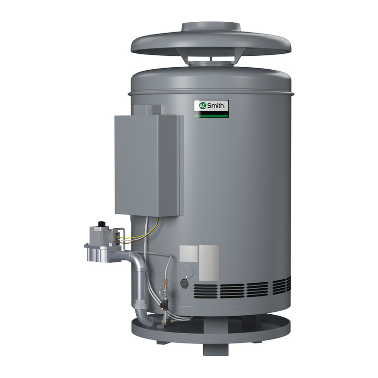
SPECIFICATION
Natural Gas Input
(Operating Range) BTU/H Min: 15,000 BTU/h
Max: 380,000 BTU/h
Propane Input
(Operating Range) BTU/H Min: 15,000 BTU/h
Max: 380,000 BTU/h
Gas Connection 1” NPT
Water Connections 1” NPT
Water Presure* psi
(Mpa)
15 - 150 psi*
(0.1 - 1.0 Mpa)
Natural Gas
Inlet pressure
" W.C.
(kPa)
Min.: 4” W.C.(1.00 kPa)
Max.: 10.5” W.C.(2.61 kPa)
Propane Gas
Inlet pressure
" W.C.
(kPa)
Min.: 8” W.C.(1.99 kPa)
Max:. 14” W.C.(3.48 kPa)
Weight lbs.
(kg)
ϭϬϮůďƐ;ϰϲϯ<ŐͿ
Dimensions Inch
(mm)
H 25.3 in. (643mm) ×
W 24.8 in. (630mm) ×
D 11.8 in. (300mm)
Ignition Electric Ignition
Electric
Supply VAC/Hz 120 VAC/60 Hz
Consumption
Operation W/A 178 W (1.48 A)
Stanby W/A 16 W (0.13 A)
Freeze-
Protection W/A 271 W (2.26 A)
Category Category III
*40 psi (0.28 Mpa) or above is recommended for
maximum flow.
**Water heater Category — water heaters of other than
direct vent type, for outdoor installation, are divided into
four categories based on static pressure produced in the
vent and flue loss.
Category I - a water heater that operates with a non-
positive vent static pressure and with a vent gas
temperature that avoids excessive condensate pro-
duction in the vent.
Category II - a water heater that operates with a non-
positive vent static pressure and with a vent gas
temperature that may cause excessive condensate
production in the vent.
Category III - a water heater that operates with a posi-
tive vent static pressure and with a vent gas tempera-
ture that avoids excessive condensate production in
the vent.
Category IV - a water heater that operates with a posi-
tive vent static pressure and with a vent gas tempera-
ture that may cause excessive condensate produc-
tion in the vent.
***These are equivalent lengths that include head loss
for elbows, tees, unions, etc.
NOTE:
ͻ ŚĞĐŬƚŚĞƌĂƚŝŶŐƉůĂƚĞƚŽĞŶƐƵƌĞƚŚĂƚƚŚŝƐƉƌŽĚ-
uct matches your specifications.
ͻ The manufacturer reserves the right to discon-
tinue, or change at any time, specifications or
designs without notice and without incurring
obligation.
Contents
