A-P-A Eco-Swing 90 User manual

1
Eco-Swing 90 Door Operator
Installation Manual

2
Contents
Contents Page
Safety Advice
Eco-Swing 90 Operator Features
Technical Data
Introduction & Explanations prior to as-
sembly
Pre-Installation Instructions
Exploded Views
Parts List
Installation of Equipment
Push Unit Details
Pull Unit Details
Installation of Backplate & Module
Installation of Options
End Plate Fitting
Spindle Cover Fitting
Drive Arm Fitting - Push Type
Drive Arm Fitting - Pull Type
Display Board Setup / Calibration
WiFi Setup / Calibration
Control Unit Diagram
Wiring
WiFi
Connection to Control Unit
Log In Page
Status Page
Engineers (Settings) Page
Admin Page
Error Messages
Status Messages
Options
Display Board - Settings
Display Board / Battery Unit
Arm Extensions
Warranty
CE
2
3
4
5
6
7
8
9 to 13
14
15
16 - 17
18 - 19
20
21
22 - 24
25 - 27
28
29 - 30
31
32 - 36
37
38
39
40
41
42
43
44
45
46
47
48
Page

3
This manual is designed to give you the correct information to assemble and install this swing door
operator to the current EN 16005 : 2012 regulations
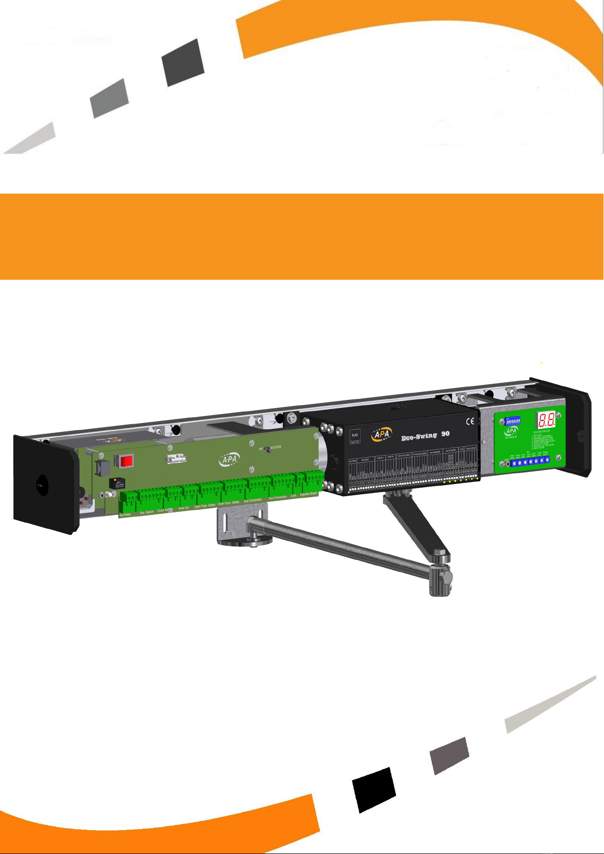
The ES-90 swing door operator has been designed by engineers with many years experience in the
automatic door industry and built on proven, reliable designs, incorporating the latest wireless
technology which interfaces the unit to any Wi-Fi browser for easy set-up and adjustment features.
An optional adjuster board can be added to give a certain level of manual adjustment / settings if
preferred.
This unit should be installed as per the instructions in this manual and with reference to the current EN 16005
regulations by a qualied engineer.
A badly or incorrectly installed unit can cause damage to both the equipment and possible injury to people.
As with all equipment installed in the workplace which falls under the Machinery At Work Act, this operator
should be routinely inspected and serviced according to the EN16005 : 2012 regulations.
We recommend this is carried out at least twice yearly by a EN16005 certied & trained engineer.
(Please note : Other regulations such as Building Regulations Part “P” or Disability Discrimination Act may
need to apply as well)
This unit is designed to be used indoors, in a dry environment only.
Safety First
Environmental Requirements
The Eco-Swing 90 contains electronics and batteries that may have materials that could be
hazardous to the environment. Please dispose of them responsibly & safely in accordance with your
countries laws
Safety

4
Compact 90mm X 135mm Aluminium Prole With “Easy Clip” Cover
Push & Pull Arm Systems.
Pull Arm With Integrated Guide Channel Spacing
( i.e. No Packing Of Door Channel Required)
Powerful Microprocessor Based Control System With All Options Integrated Within the
Programming / Setup. It Uses A Self Diagnostic System To Identify Faults And Make
Installations / Maintenance As Simple As Possible
Low Energy Operation
Power Assist Mode
Push and Go Option
Electric Lock Output
Fire Alarm Input (N/O or N/C Selectable)
Morning Entry / Access Control Key Input (N/O)
Safety Mat Input (N/O)
Emergency Stop Input (N/O or N/C Selectable)
Auxiliary Locking Relay ( N/O & N/C)
Master/Slave Connection
Interlocking Between Door Sets
Rebated Door Mode
Fully Monitored Safety Sensor System (EN16005 : 2012)
Easy To Use Wi Interface Set-Up Program With Status & Error Reporting
(using any wi enabled browser)
Mode Switch Options
Rocker Switch (Standard) - Key Operated Switch - LCD Key Switch
Options
Battery Back-Up
Manual Display / Adjustment Board
Arm Extension Kit
Eco-Swing 90 Features

5
Technical Details
Min Door Width
Max Door Width
Max Door Height
Max Door Weight
Unit Weight
Max opening angle
Mains Voltage
Hold Open time
Opening Speed
Closing Speed
Auxiliary Power Supply 2
Ambient Temp -
Protection Class
700mm
1200mm
2500mm
200 kgs
14Kg
110 Degrees
80v - 250 v ac 50 Hz
0 – 60 Sec
3 – 6 Seconds
3 – 6 Seconds
24v dc - 2000 mA
- 20 to +45
IP 20

6
Introduction
Eco-Swing 90
The Eco-Swing 90 is an electro-mechanical operator designed to open and close doors under the
control of a microprocessor control system designed to comply with EN 16005 : 2012 regulations.
It has been designed to be easily installed and has clear / simple, setup / adjustment procedures
It is housed in a two part aluminium housing (as above) with an”easy clip” cover.
All the main components are mounted on a module plate which allows for quick and easy removal of
all the internal parts for ease of tting and / or repair.
The operator is a powered open / spring close unit operating under the control of specialised
software.
The Eco-Swing 90 has been developed to adapt to all situations and therefore comes with a wide
range of optional settings and easy to understand connections.
Using the latest technology and it comes with “Built in” Wi which means it can be set up and
adjusted from any WiFi enabled device with a browser (i.e. Phone, Tablet, Laptop) independent of
the operating system of the device. This makes the setup / adjustments incredibly easy.
An option Display / Adjuster board is available if manual settings are preferred (ie dip switches &
adjuster)

7
• Make sure all installation areas are clear and suitably reinforced to take the pressure of a pow-
ered door operator
• Check all pivots & hinges are in good working order and not worn.
• Check a suitable and sucient risk assessment has been undertaken.
• Check you have the correct operator for type of door operation ie Push or Pull unit.
• Check you have all parts to complete the installation before commencing.
Eco-Swing 90 Fitting Template
Set of Metric Allen Keys ( 4mm / 5mm / 6mm / 8mm)
A drill and drill bits
Set of screwdrivers of various types / sizes
A marking device ( ie pencil)
• The Eco-Swing 90 operator is mounted to the area above the door, be it either framework or
other (such as concrete lintel / wooden stud work)
• The area to which the operator is mounted should be checked to ensure it is suitable to take the
weight of the operator and any imposed loads.
• Always use the correct type of xing for the materials being xed to
Aluminium Frame / Doors
Steel
Wood
Brick
5mm
5mm
50mm No10 Wood Screws
Concrete/Brick Fixers or Raw plugs & Screws
Material Fixing To Minimum Recommended Fixings
Pre-Installation
Tools Needed To Install An Eco-Swing 90 Unit
Notes Prior To Installation

8
Exploded View
Eco-Swing 90 Pull Unit
Eco-Swing 90 Push Unit

9
Parts List
Part No : 3005042
Part No : 3005043
Part No : 3005034
Part No : 3005031
Motor Gear Box
1
Part No : 3005014
Module Plate
Module Fittting Bars
Part No : 3005026 - PULL
Part No : 3005026 - PUSH
1
1
2
Module Plate
Module Fitting Bars
Control Unit
Motor / Gearbox Unit
Fitting Kit
Part No : 3005010
Fittings Kit
Control Unit
1
Aluminium Cover
1
Fitting Backplate
1
Operator Cover
Operator Backplate

10
Parts-Arms
Standard - Part No : 3005012
Fitting Angle & Ball
1
Push Arm Connector Joint & Bolt
1
Push Arm Rod & Ball Joint
1
Push Arm Joint
Push Arm Rod with Ball Joint
Door Fitting - Angle with Ball Fitting
Part No : 3005078
Part No : 3005075
Metal Frame - Part No : 3005076
Connection Boss & Arm Fitting Bolt
1
Pull Arm
1
Standard Connection Boss for both push &
Pull Arms
Pull Arm With Roller Wheel
Part No : 3005045
Part No : 3005017
Part No : 3005036
Part No : 3005019
Push Arm Flat Bar with Bearing
1
Aluminium Arm Channel with Intergrated
Spacer
Push Arm - Flar Bar With Bearing
Pull Arm Channel
1

11
Push Arm - Centre Pivoted Door
Part No : 3005027
1
Push Arm - Aluminium Door
Push Arm Set - Standard
Push Arm - Std - Hinged Door
Part No : 3005016
1
Pull Arm Set
Pull Arm & Track
Part No : 3005019
1
Parts-Arms Complete

12
Pull Arm Cap - Right Hand
1
Spindle Cover Grommet
1
Pull Arm Cap - Left Hand
1
Spindle Shaft Grommet
Pull Arm Channel Cover - L/H
Pull Arm Channel Cover - R/H
Part No : 3005049
Standard End Plate
1
Rocker Switch Plate
1
Plain End Plate
Standard Rocker Switch End Plate
Part No : 3005038
Part No : 3005038
Part No : 3005040
Part No : 3005018
Part No : 3005046
Spindle Shaft Cover
2
LCD Switch End Plate
Spindle Shaft Cover
LCD Switch Plate - Optional
1
Part No : 3005039
Parts-Plastic Items

13
Parts-Optional Extras
1
Part No : 3005063
1
Arm Extension - 20mm
Arm Extension - 50mm
Arm Extension - 70mm
Part No : 3005017
Part No : 3005061
Part No : 3005062
Arm Extension - 70mm
1
Arm Extension - 20mm
Battery / Display Board Bracket
1
Display Board
1
Battery / Display Board Bracket
Part No : 3005044
Display Board Unit
Part No : 3005015
1
Arm Extension - 50mm
Battery Strap / Fittings & Batteries
Battery Backup Kit
1
Connection Boss - For use with extension
parts
Part No : 3005022
Extension Connection Boss

14
Installation
Push Unit Installation Details
Use the dimensions as set-out below to position the unit backplate in correct position.
Note : Rear of backplate is positioned 30mm past the pivot point.

15
Installation
Pull Unit Installation Details
Installation
Use the dimensions as set-out below to position the unit backplate in correct position.
Note : Rear of backplate is positioned 30mm past the pivot point.

16
Installation
Within the backplate is pre-tted xing bars to which all xings are secured for the tting of the
module plate.
Ensure all module bolts (black head) are tted and loose.
After drilling correct tting holes (9 o), x the backplate to the transom area using appropriate xings.
We recommend you use countersunk xings
as this will give maximum clearance between
the backplate and module plate for running
any wiring.

17
Installation
The tting system uses a “keyhole type tting which allows the plate to t over the head of the bolt
and slide sidewards to a position in which it can be secured.
Fit module over the bolts protruding from the xing bars.
Slide the complete module assembly towards the control unit end & secure module by tightening all
(8) M6 bolts.

18
Installation-Options Installation-Options
Unit tted with both optional Display /
Adjustment Board & Battery Backup Pack
Once the module assembly is installed and secured, then add any additional parts such as
battery pack or display board & bracket. Add the (4) x M6 bolts supplied by partially screwing into the
module plate. Fit the bracket to the module plate R/H side of the bolts and slide to left and secured
the bolts.
The connection lead for the display board or the battery pack is routed behind the module plate and
is brought out through the opening under the motor.
The optional Display / Adjuster Board & Battery back-up are tted to the same bracket.
If tting both, the battery pack ts to the rear of the bracket with a strap secured by 2 M5 screws
The display board is mounted on the front of the bracket and the (4) x M3 “stand-o’s” are tted to the
bracket using the holes provided.
The bracket is mounted on the hinge side of the operator and attached to (4) x M6 bolts screwed
into the module plate as shown below.

19
Installation-Options
The battery pack ts to the rear of the bracket with a strap secured by (2) x M5 screws.
The batteries are connected by (2) extension leads with are routed down through the bracket and under
the module plate. They are brought up under the motor and plugged into the rear side of the PCB.
The Display / Adjuster board ts to the front of the bracket with (4) x M3 ttings.
The unit comes tted with a connection cable and plug and is routed down through the bracket and
under the module plate.
They are brought up under the motor and plugged into R/H of the PCB connection block.
Also add any other wiring such as mains power lead or sensors leads.
Unit tted with optional Battery
Backup Pack only
Unit tted with optional Display /
Adjustment Board only

20
The next step is to install the operator end plates. These are plastic and once aligned, will knock gently
by tapping into place using your hand or a soft mallet. No xings are required.
Each end plate has (2) lugs which align with the backplate channel prole.
Installing the “End Plates”
Installation
With a standard operator, one of the end plates will contain the “3” position rocker ” switch for setting
the modes.
On a single & double door with separate operators, this can be placed either end.
On a double door set with extended cover tted, this will need to be tted on the hinge side.
This is connected to the “mode switch connection terminal” on the control unit with the supplied cable
Table of contents
Popular Gate Opener manuals by other brands

Power Master
Power Master rsw installation manual

US Automatic
US Automatic PATRIOT RSL troubleshooting guide

HySecurity
HySecurity HydraSwing 40 Programming and operations manual

G-Force
G-Force DSG 5 DC2 Installation and setup instructions

ZHEJIANG XIANFENG MACHINERY
ZHEJIANG XIANFENG MACHINERY K207A user manual

CARDIN ELETTRONIC
CARDIN ELETTRONIC 200/BL202 instruction manual

CAME
CAME BKS08ALS installation manual

Erreka
Erreka AMO02 quick start guide

Roger Technology
Roger Technology G30/1804 INSTRUCTIONS AND RECOMMENDATIONS FOR THE INSTALLER

Chamberlain
Chamberlain SL 1000-XI Installation & operating instructions

DITEC
DITEC Entrematic FACIL3H quick reference

DKS
DKS 66011200 Installation and owner's guide