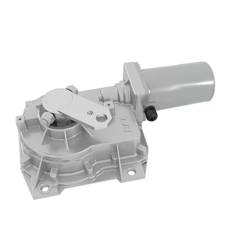
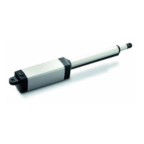
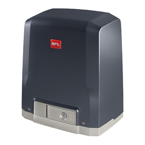
BFT LEM7 User manual

ISTRUZIONI D'USO E DI INSTALLAZIONE
INSTALLATION AND USER'S MANUAL
INSTRUCTIONSD'UTILISATIONETD'INSTALLATION
INSTALLATIONS-UND GEBRAUCHSANLEITUNG
INSTRUCCIONES DE USO Y DE INSTALACION
INSTRUÇÕES DE USO E DE INSTALAÇÃO
D811025A ver. 01 18-03-05
I
GB
F
D
E
P
LEM7 - LEM8F
ACTUATOR FOR RACK SLIDING GATES
ACTIONNEUR POUR PORTAILS COULISSANTS A CREMAILLERE
AUTOMATIONEN FUER SHIEBEGITTERTORE MIT ZAHNSTANGE
SERVOMOTOR PARA CANCELAS CORREDERAS DE CREMALLERA
ACCIONADOR PARA PORTÖES DE CORRER A CREMALLERA
ATTUATORE PER CANCELLI SCORREVOLI A CREMAGLIERA
8 027908 111586

2 -
LEM7 LEM8F Ver. 01
D811025A_01

LEM7 LEM8F Ver. 01 -
3
D811025A_01
MANUALE D’USO ITALIANO
NelringraziarViperla preferenzaaccordata aquesto prodotto,la dittaècerta che
da esso otterrete le prestazioni necessarie al Vostro uso. Leggete attentamente
l’opuscolo “Avvertenze”ed il “Libretto istruzioni”che accompagnano questo
prodotto in quanto forniscono importanti indicazioni riguardanti la sicurezza,
l’installazione, l’uso e la manutenzione. Questo prodotto risponde alle norme
riconosciute della tecnica e della disposizioni relative alla sicurezza. Confermia-
mo che èconforme alle seguenti direttive europee: 89/336/CEE, 73/23/CEE (e
loro modifiche successive).
1) GENERALITÀ
L'attuatore della serie LEM, ècostituito da un motoridottore con pignone
che si accoppia al cancello per mezzo di una cremagliera. La centralina di
comando puòessere incorporata o esterna.
La logica di funzionamento permette diverse configurazioni per meglio
adattare l'uso dell'automazione all'utente (es.: chiusura automatica, chiu-
sura comandata, fotocellule attive in chiusura ecc.). Per modificare le
impostazioni, rivolgersi a personale qualificato (installatore).
Il motoriduttore di tipo irreversibile, mantiene l'anta bloccata in chiusura
rendendo superfluo l'uso di elettroserrature.
Il motoriduttore èdotato di frizione meccanica antischiacciamento che
deve essere tarata e controllata periodicamente da personale qualificato.
La serie LEM8F èdotata di freno motore di tipo elettromagnetico che
consente arresti precisi dell'anta.
L'apertura manuale dell'anta, si esegue con estrema facilitàper mezzo di
una manopola di sblocco.
2) SICUREZZA
L'automazione, se installata ed utilizzata correttamente, soddisfa il grado
di sicurezza richiesto.
Tuttavia èopportuno osservare alcune regole di comportamento per
evitare inconvenienti accidentali.
Prima di usare l'automazione, leggere attentamente le istruzioni d'uso e
conservarle per consultazioni future.
•Tenere bambini, persone e cose fuori dal raggio d'azione dell'automazio-
ne, in particolare durante il funzionamento.
•Non l'asciare radiocomandi o altri dispositivi di comando a portata dei
bambini, onde evitare azionamenti involontari dell'automazione.
•Non contrastare volontariamente il movimento dell'anta.
•Non tentare di aprire manualmente il cancello se non èstato attivato lo
sblocco di emergenza
•Non modificare i componenti dell'automazione.
•In caso di malfunzionamento togliere l'alimentazione, attivare lo sblocco
di emergenza per consentire l'accesso e richiedere l'intervento del tecni-
co qualificato.
•Per ogni operazione di pulizia, togliere l'alimentazione di rete.
•Tenere pulito; la guida di scorrimento, le ottiche delle fotocellule ed i
dispositivi di segnalazione luminosa. Controllare che rami e arbusti non
disturbino i dispositivi di sicurezza (fotocellule) o il movimento dell'anta.
•Periodicamente, controllare la lubrificazione della cremagliera. Se in
materiale plastico non deve essere lubrificata.
•Per qulsiasiinterventodiretto all'automazione,avvalersidi personale qua-
lificato (installatore).
•Annualmente far controllare l'automazione da personale qualificato.
3) MANOVRA DI EMERGENZA
L’apertura manuale dell'anta va eseguita quando manca l'energia elettrica
o in caso di disservizzi dell'automazione. Ci sono due tipi di manopole che
sono: A) Manopola estraibile
B) Manopola con chiave personalizzata
Manopola "A" (fig.1)
•Inserire la manopola di sblocco nell'apposita sede e ruotare in senso
orario per tutta la sua corsa.
•Spingere manualmente l'anta del cancello.
•Per ripristinare il funzionamento motorizzato o per mantenere il cancello
bloccato in chiusura, ruotare la manopola in senso antiorario per tutta la
suacorsa,muoveremanualmentel'antafino all'innestodeltrascinamento,
togliere la manopola e riporla in luogo conosciuto agli utilizzatori.
•Quando ritorna l'energia elettrica l'automazione funzioneràin modo
motorizzato.
Manopola "B" (fig. 2-3)
Nel caso si utilizzi la manopola di blocco con chiave personalizzata (fig.2-
3) agire come segue:
•Inserire la chiave personalizzata (fig.2) nella serratura della manopola e
ruotarla in senso antiorario fno a percepire uno scatto .
•Ruotare la manopola di sblocco in senso orario per tutta la sua corsa
(fig.2).
•Spingeremanualmente l'anta.Lachiavepersonalizzata,nonsipuòestrarre
fino a quando si ripristina il funzionamento motorizzato.
•Per ripristinare ilfunzionamentomotorizzato,ruotare lamanopolain senso
antioario, ruotare la chiave in senso orario fino ad estrarla.
•Riporre una chiave in un luogo noto agli utilizzatori.
4) MANUTENZIONE E DEMOLIZIONE
La manutenzione dell’impianto va fatta eseguire regolarmente da parte di
personale qualificato. I materiali costituenti l’apparecchiatura e il suo imballo
vanno smaltiti secondo le norme vigenti.
AVVERTENZE
Il buon funzionamento dell’operatore è garantito solo se vengono rispet-
tate i dati riportati in questo manuale. La ditta non risponde dei danni
causati dall’inosservanza delle norme di installazione e delle indicazioni
riportate in questo manuale.
Le descrizioni e le illustrazioni del presente manuale non sono impegna-
tive. Lasciando inalterate le caratteristiche essenziali del prodotto, la Ditta
siriservadiapportarein qualunquemomento lemodifichecheessaritiene
convenienti per migliorare tecnicamente, costruttivamente e commercial-
mente il prodotto, senza impegnarsi ad aggiornare la presente pubblica-
zione.
Fig.1
Fig.2
Fig.3

4 -
LEM7 LEM8F Ver. 01
D811025A_01
USER’S MANUAL
Thank you for buying this product, our company is sure that you will be more
than satisfied with the product’s performance. The product is supplied with
a “Warnings”leaflet and an “Instruction booklet”. These should both be
readcarefullyas theyprovideimportant informationaboutsafety, installation,
operation and maintenance. This product complies with the recognised
technical standards and safety regulations. We declare that this product is
in conformity with the following European Directives: 89/336/EEC and 73/
23/EEC (and subsequent amendments).
1) GENERAL OUTLINE
The LEM series actuator consists of a gearmotor with a pinion which is
coupled with the gate by means of a rack. The control unit can be
incorporated or external.
The function logic allows various configurations to be obtained in order to
suit the automation system to the user’s needs (e.g.: automatic closing,
controlled closing, photocells active on closing etc.). To modify the settings,
contact a qualified person (installer).
The irreversible-type gearmotor keeps the leaf locked on closing, thus
making the use of electric locks redundant.
The gearmotor is provided with an antisquash mechanical clutch, which
must be periodically calibrated and checked by qualified personnel.
The LEM8F series is provided with an electromagnetic-type motor brake
which allows the leaf to stop with precision.
Manual leaf opening is made extremely easy by means of a release knob.
2) SAFETY
If correctly installed and used, this automation device satisfies the required
safety level standards. However, it is advisable to observe some practical
rules in order to avoid accidental problems.
Beforeusingthe automation device,carefullyread the operationinstructions
and keep them for future reference.
•Keep children, persons and things outside the automation working area,
particularly during operation.
•Keep radio control or other control devices out of children’s reach, in order
to avoid any unintentional automation activation.
•Do not intentionally oppose the leaf movement.
•Do not attempt to open the gate by hand, if the actuator has not been
released by means of the appropriate release knob.
•Do not modify the automation components.
•Incase ofmalfunction, disconnectthe powersupply,activatetheemergency
release to gain access to the actuator and request the assistance of a
qualified technician (installer).
•Before proceeding to any external cleaning operation, disconnect the
mains powers supply and at least one of the battery pole, if fitted.
•Keep the photocell optical components and luminous signal indication
devicesclean.Checkthat thesafety devices(photocells) arenotobscured
by branches or shrubs.
•Foranydirectassistancetothe automationsystem, requesttheassistance
of a qualified technician (installer).
•Have qualified personnel check the automation system once a year.
3) MANUAL RELEASE
Manual leaf opening is to be carried out in case of power supply failure or
automation inefficiency. Two types of knobs are available:
A) Pull-out knob
B) Personalised key-knob
Knob “A” (fig.1)
•Insert the release knob in the appropriate seat, and rotate it clockwise
along its entire travel.
•Push the gate leaf by hand.
•Inorderto resetmotor-drivenoperationor keepthegate lockedonclosing,
rotate the knob anticlockwise along its entire travel, move the leaf by hand
until it reaches its dragging point, remove the knob and keep it in a place
known to all users.
•Whenthepowersupply comes backon, theautomation devicewill resume
motor-driven operation.
Knob “B” (fig. 2-3)
In the case where a locking knob with a personalised key (fig.2-3) is used,
proceed as follows:
•Insert the personalised key (fig.2) in knob lock, and rotate the knob
anticlockwise until a click is heard.
•Rotate the release key clockwise along its entire travel (fig.2).
•Push the leaf by hand. The personalised key cannot be pulled out until
motor-driven operation is reset.
•In order to reset motor-driven operation, rotate the knob anticlockwise,
and rotate the key clockwise until it comes out.
•Keep the key in a place known to all users.
ENGLISH
4) MAINTENANCE AND DEMOLITION
The maintenance of the system should only be carried out by qualified
personnel regularly.The materials making up the set and its packing must
be disposed of according to the regulations in force.
WARNINGS
Correct controller operation is only ensured when the data contained
in the present manual are observed. The company is not to be held
responsible for any damage resulting from failure to observe the
installation standards and the instructions contained in the present
manual.
The descriptions and illustrations contained in the present manual
arenotbinding. TheCompanyreserves theright tomakeany alterations
deemed appropriate for the technical, manufacturing and commercial
improvement of the product, while leaving the essential product
features unchanged, at any time and without undertaking to update
the present publication.
Fig.1
Fig.2
Fig.3

LEM7 LEM8F Ver. 01 -
5
D811025A_01
MANUEL D’UTILISATION FRANÇAIS
Nousvousremercions pouravoirchoisi ceproduit.Nous sommescertainsqu’il
vous offrira les performances que vous souhaitez. Lisez attentivement la
brochure “Avertissements”et le “Manuel d’instructions”qui accompagnent
ce produit, puisqu’ils fournissent d’importantes indications concernant la
sécurité, l’installation, l’utilisation et l’entretien. Ce produit est conforme aux
règles reconnues de la technique et aux dispositions de sécurité. Nous
certifions sa conformitéavec les directives européennes suivantes: 89/336/
CEE, 73/23/CEE (et modifications successives).
1) GENERALITES
L’actionneur de la série LEM est constituéd’un moto-réducteur avec pignon
accoupléau portail au moyen d’une crémaillère. L’unitéde commande peut
être incorporée ou externe.
La logique de fonctionnement permet plusieurs configurations afin de mieux
adapter la motorisation aux exigences de l’utilisateur (ex.: fermeture
automatique, fermeture commandée, cellules photoélectriques actives en
fermeture etc.). Pour modifier les réglages, s’adresser àun personnel qualifié
(installateur).
Le moto-réducteur est du type irréversible, il maintient le vantail bloquéen
fermeture, ce qui rend inutile l’emploi d’une serrure électrique.
Le moto-réducteur est dotéd’un embrayage mécanique antiécrasement qui
doit être régléet contrôlépériodiquement par un personnel qualifié.
La série LEM8F est dotée d’un frein moteur de type électromagnétique qui
permet des arrêts précis du vantail.
L’ouverture manuelle du vantail se fait d’une façon très facile au moyen d’une
poignée de déblocage.
2) SECURITE
La motorisation, si installée et utilisée correctement, est conforme au degréde
sécuritédemandé. Il est toutefois conseilléde respecter ces quelques règles
de conduite afin d’éviter tout inconvénient ou accident. Avant d’utiliser la
motorisation, lire attentivement les instructions d’utilisation et les conserver en
cas de besoin.
•Tenir les enfants, les personnes et les choses hors du rayon d’action de la
motorisation, particulièrement pendant le fonctionnement.
•Ne pas laisser les radio commandes ou d’autres dispositifs de commande
àla portée des enfants, afin d’éviter des actionnements involontaires de la
motorisation.
•Ne pas contraster volontairement le mouvement du portail.
•Ne pas chercher àouvrir manuellement le portail si l’actionneur n’a pas été
débloquéavec la poignée de déblocage spéciale.
•Ne pas modifier les composants de la motorisation.
•En cas de mauvais fonctionnement, couper l’alimentation, activer le
déblocage d’urgence afin de permettre l’accès et demander l’intervention
d’un technicien qualifié(installateur).
•Pour toute opération de nettoyage extérieur, couper l’alimentation de ligne
et, si présent, au moins un pôle des batteries.
•Nettoyer les optiques des cellules photoélectriques et les dispositifs de
signalisation lumineuse. S’assurer que des branches ou des arbustes ne
dérangent pas les dispositifs de sécurité(cellules photoélectriques).
•Pour touteinterventiondirectesurlamotorisation,s’adresseràdupersonnel
qualifié(installateur).
•Chaque année, faire contrôler la motorisation par du personnel qualifié.
3) MANOEUVRE D’URGENCE
L’ouverture manuelle du vantail doit être effectuée en cas de faute d’électricité
ou en cas de mauvais fonctionnement de l’automatisme. Les poignées
peuvent être de deux types:
A) Poignée extractible
B) Poignée avec clépersonnalisée
Poignée «A» (fig. 1)
•Insérer la poignée de déblocage dans le logement spécial et tourner dans
le sens des aiguilles d’une montre pour toute sa course.
•Pousser manuellement le vantail du portail.
•Pour rétablir le fonctionnement motoriséou pour maintenir le portail bloqué
en fermeture, tourner la poignée dans le sens contraire àcelui des aiguilles
d’unemontrepour toutesa course,déplacerlevantail manuellementjusqu’à
l’engagement de l’entraînement, enlever la poignée et la ranger dans un
endroit connu par les utilisateurs.
•Au rétablissement de l’alimentation électrique, la motorisation fonctionnera
de façon motorisée.
Poignée «B» (fig. 2-3)
Si on utilise la poignée de blocage avec clépersonnalisée (fig. 2-3), agir
comme suit:
•Insérer la clépersonnalisée (fig. 2) dans la serrure de la poignée et la
tourner dans le sens contraire àcelui des aiguilles d’une montre jusqu’à
entendre un déclic.
•Tourner la poignée de déblocage dans le sens des aiguilles d’une montre
pour toute sa course (fig. 2).
•Pousser manuellementle vantail.La clépersonnaliséene peutêtreenlevée
qu’après avoir rétabli le fonctionnement motorisé.
•Pour rétablir le fonctionnement motorisé, tourner la poignée dans le sens
contraire àcelui des aiguilles d’une montre, tourner la clédans le sens des
aiguilles d’une montre jusqu’à l’enlever.
•Ranger la clédans un lieu connu par les utilisateurs.
Fig.1
Fig.2
Fig.3
4) ENTRETIEN ET DEMOLITION
L’entretien de l’installation doit être effectuérégulièrement de la part de
personnel qualifié. Les matériaux constituant l’appareillage et son emballage
doivent être mis au rebut conformément aux normes en vigueur. Les piles
constituent des déchets spéciaux.
AVERTISSEMENTS
Le bon fonctionnement de l’actionneur n’est assuré que si les données
fourniesdanscemanuelsontrespectées.Le constructeurne répondpas
pour les dommages provoqués par le non respect des normes
d’installation et des indications fournies dans ce manuel.
Les descriptions et les figures de ce manuel n’engagent pas le
constructeur. En laissant inaltérées les caractéristiques essentielles du
produit,laSociété se réserveledroit d’apporteràn’importe quel moment
les modifications qu’elle juge opportunes pour améliorer le produit du
point de vue technique, commercial et de construction, sans s’engager
à mettre à jour cette publication.

6 -
LEM7 LEM8F Ver. 01
D811025A_01
BEDIENUNGSANLEITUNG
DEUTSCH
Wir danken Ihnen, daßSie sich für diese Anlage entschieden haben. Ganz
sicher wird sie mit ihren Leistungen Ihren Ansprüchen vollauf gerecht
werden. Lesen Sie aufmerksam die Broschüre “Hinweisen“und die
“Gebrauchsanweisung“durch, die dem Produkt beiliegen. Sie enthalten
wichtige Hinweise zur Sicherheit, Installation, Bedienung und Wartung der
Anlage. Dieses Produkt genügt den anerkannten technischen Regeln und
Sicherheitsbestimmungen. Wir bestätigen, daßes mit folgenden
Europäischen Richtlinien übereinstimmt: 89/336/EWG, 73/23/EWG (und
ihren nachfolgende Änderungen).
1) ALLGEMEINES
Die Antriebe der Serie LEM bestehen aus einem Getriebemotor mit Ritzel,
der durch eine Zahnstange mit dem Tor verbunden wird. Die Steuerung ist
als integrierte oder externe Version erhältlich.
Mit der Funktionslogik läßt sich die Anlage unterschiedlich konfigurieren
und optimal an die vorhandene Anlage des Benutzers anpassen (Bsp:
Schließautomatik, Schließsteuerung, Fotozellen während der Schließung
aktiv etc.). Zur Änderung der Einstellung wenden Sie sich bitte an Ihren
Fachmann (Installateur).
Der Getriebemotor ist irreversibel, der Flügel bleibt im geschlossenen
Zustand versperrt und macht dadurch die Verwendung eines
Elektroschlosses überflüssig.
Der Quetschschutz der Anlage, eine mechanische Kupplung, muß
regelmäßig von Fachleuten justiert und kontrolliert werden.
Die Serie LEM8F verfügt außerdem über eine elektromagnetische
Motorbremse als Garant für präzise Torstops.
Der Flügel läßt sich mit Hilfe eines Entsperrgriffes spielend leicht von Hand
öffnen.
2) SICHERHEIT
Die Anlage erfüllt bei richtiger Installation und Bedienung die erforderlichen
Sicherheitsstandards.Trotzdemist es sinnvoll,einigeVerhaltensmaßregeln
zu beachten, um unvorhergesehene Zwischenfälle auszuschließen.
Vor Gebrauch der Anlage die Betriebsanleitung aufmerksam lesen und für
zukünftige Einsichtnahme aufbewahren.
•Kinder, Erwachsene und Sachwerte sollten sich außerhalb des Wirk-
radius der Anlage befinden, besonders während des Betriebes.
•Keine Fernbedienungen oder andere Steuerungsvorrichtungen in Reich-
weite von Kindern liegen lassen. Sie könnten die Anlage ungewollt in
Gang setzen.
•Der Flügelbewegung nicht willentlich Kraft entgegensetzen.
•Nicht versuchen, das Tor von Hand zu öffnen, wenn nicht vorher der
Antrieb mitdementsprechenden Entriegelungshandgriffentsperrt wurde.
•Keine Umbauten an Anlagenkomponenten vornehmen.
•Bei Betriebsstörungen die Stromversorgung unterbrechen, durch Betä-
tigung der Notentriegelung den Zugang ermöglichen und einen fach-
kundigen Techniker (Installateur) hinzuziehen.
•Vor jeder Außenreinigung die Stromversorgung unterbrechen und - falls
vorhanden - zumindest einen Batteriepol abklemmen.
•Halten Sie die Linsen der Lichtschranken und die Blinkleuchte sauber.
Prüfen Sie, ob Äste oder Gesträuch die Sicherheitsvorrichtun-gen
beeinträchtigen können (Lichtschranke).
•Wenn eine Arbeit unmittelbar an der Anlage erforderlich ist, wenden Sie
sich hierzu an fachkundiges Personal (Installateur).
•Die Anlage mußeinmal jährlich von Fachpersonal kontrolliert werden.
3) BEDIENUNG IM NOTFALL
Der Flügel mußvon Hand geöffnet werden, wenn der Strom ausgefallen ist
oder die Anlage nicht funktioniert. Es gibt zwei Arten von Handgriffen:
A) Herausziehbarer Handgriff
B) Handgriff mit persönlichem Schlüssel
Handgriff „A“ (Abb. 1)
•Stecken Sie den Entsperrgriff in seinen Sitz und drehen ihn dann im
Uhrzeigersinn einmal ganz um.
•Schieben Sie den Torflügel mit der Hand auf.
•Um den Motorbetrieb wieder aufzunehmen oder das Tor im
geschlossenen Zustand zu blockieren, drehen Sie den Handgriff gegen
den Uhrzeigersinn einmal ganz um, bewegen den Flügel bis zum
Einrasten der Zugvorrichtung, entfernen den Griff und legen ihn an
einem Ort ab, der allen Beteiligten bekannt ist.
•Wenn der Strom wieder da ist, wird der Motorbetrieb erneut
aufgenommen.
Handgriff „B“ (Abb. 2-3)
Wird ein Entsperrgriff mit personalisiertem Schlüssel benutzt (Abb. 2-3),
sieht die Vorgehensweise so aus:
•SteckenSiedenpersönlichenSchlüssel(Abb.2)indasSchloßdesHandgriffes
und drehen ihn gegen den Uhrzeigersinn, bis ein Ruck zu spüren ist.
•Nun den Entsperrgriff im Uhrzeigersinn einmal ganz umdrehen (Abb.2).
•Den Flügel von Hand schieben. Der Schlüssel bleibt solange stecken,
bis der Motorbetrieb wieder aufgenommen wird.
•Um den motorisierten Torantrieb wieder funktionsfähig zu machen,
drehen Sie den Griff gegen den Uhrzeigersinn und den Schlüssel im
Uhrzeigersinn, bis man ihn abziehen kann.
Fig.1
Fig.2
Fig.3
•Legen Sie einen Schlüssel an einen Ort, der allen Beteiligten bekannt
ist.
4) INSTANDHALTUNG UND VERSCHROTTUNG
Die Anlagenwartung ist regelmäßig von Fachleuten vorzunehmen.
Die Materialien, aus denen die Apparatur besteht und ihre Verpackung sind
vorschriftsmäßig zu entsorgen. Die Batterien dürfen nicht in die Umwelt
gelangen.
HINWEISE
Der einwandfreie Betrieb des Antriebes ist nur dann garantiert, wenn die
Angaben aus diesem Handbuch beachtet werden. Der Hersteller haftet
nicht für Schäden, die durch Mißachtung der Installationsanweisungen
und der Angaben aus diesem Handbuch entstehen.
Die Beschreibungen und bildlichen Darstellungen in diesem Handbuch
sind unverbindlich. Der Hersteller behält sich - ohne auch zur
Aktualisierung dieser Unterlagen verpflichtet zu sein - jederzeit vor,
Änderungen vornehmen, wenn er diese für technische oder bauliche
Verbesserungen als notwendig erachtet und die wesentlichen
Produkteigenschaften unverändert bleiben.

LEM7 LEM8F Ver. 01 -
7
D811025A_01
MANUAL DE USO ESPAÑOL
Al agradecerle la preferencia que ha manifestado por este producto, la empresa
estásegura de que de él obtendrálas prestaciones necesarias para sus
exigencias. Lea atentamente el folleto “Advertencias”y el “Manual de
instrucciones”queacompañana esteproducto,puesproporcionanimportantes
indicaciones referentes a la seguridad, la instalación, el uso y el mantenimiento
del mismo.
Esteproductocumplelosrequisitos establecidospor lasnormasreconocidasde
la técnica y las disposiciones relativas a la seguridad. Confirmamos su
conformidad con las siguientes directivas europeas: 89/336/CEE, 73/23/CEE (y
modificaciones sucesivas).
1) INFORMACIONES GENERALES
El actuador de la serie LEM, consta de un motoreductor equipado con piñón que
se acopla a la cancela por medio de una cremallera. La central de control puede
ser tanto incorporada como externa.
La lógica de funcionamiento permite diferentes configuraciones, para adaptar
mejor la utilización de la automación al usuario (por ejemplo: cierre automático,
cierre controlado, fotocélulas activas en la posición de cierre, etc.). Para
modificar las programaciones, recurrir a personal capacitado (instalador).
El motoreductor, de tipo irreversible, mantiene la hoja bloqueada en la posición
de cierre, haciendo superflua la utilización de electrocerraduras.
El motoreductor se ha equipado con embrague mecánico antiaplastamiento
que debe venir ajustado y controlado periódicamente por parte de personal
capacitado. La serie LEM8F se ha equipado con freno motor de tipo
electromagnético que permite detenciones precisas de la hoja.
La apertura manual de la hoja se ejecuta con extrema facilidad por medio de un
pomo de desbloqueo.
2) SEGURIDAD
El automatismo, si se instala y utiliza correctamente, satisface el grado de
seguridad requerido. Sin embargo, es conveniente observar algunas reglas de
comportamiento para evitar inconvenientes accidentales. Antes de usar el
automatismo, lea atentamente las instrucciones de uso y consérvelas para
consultas futuras.
•Mantener a niños, personas y cosas fuera del campo de acción del automa-
tismo, especialmente durante su funcionamiento.
•No dejar radiomandos u otros dispositivos de mando al alcance de los niños,
para evitar el accionamiento involuntario del automatismo.
•No contrastar voluntariamente el movimiento de la hoja.
•No intentar abrir manualmente la cancela si antes no se ha desbloqueado el
servomotor con la manecilla de desbloqueo.
•No modificar los componentes del automatismo.
•En caso de mal funcionamiento, cortar el suministro de corriente, activar el
mecanismode desbloqueo deemergencia paraconsentirelacceso ysolicitar
la intervención de un técnico cualificado (instalador).
•Antesde realizarcualquier operacióndelimpiezaexterna, cortar elsuministro
de corriente y, si estápresente el kit de baterías tampón, desconectar al
menos un polo de las baterías.
•Mantenerlimpias laslentesdelasfotocélulasylosdispositivos deseñalización
luminosa.Controlar que ramas o arbustos no interfieran con los dispositivos
de seguridad (fotocélulas).
•Si resulta necesario efectuar una intervención directa en el automatismo,
llamar a personal cualificado (instalador).
•Una vez al año, es preciso hacer controlar el automatismo por personal
cualificado.
3) MANIOBRA DE EMERGENCIA
La apertura manual de la hoja debe ejecutarse en el caso de que falte la energía
eléctrica o en caso de ineficiencias de la automación: Hay dos tipos de pomos,
que son:
A) Pomo que se puede sacar
B) Pomo con llave personalizada
Pomo “A” (figura 1)
•Introducir el pomo de desbloqueo en el específico alojamiento y girarlo en
sentido horario por toda su carrera.
•Empujar manualmente la hoja de la cancela.
•Para restablecer el funcionamiento motorizado y para mantener la hoja
bloqueadaen posiciónde cierre,girarelpomo ensentido antihorariopor toda
su carrera, mover manualmente la hoja hasta la inserción del arrastre, sacar
el pomo y guardarlo en un lugar conocido solamente por los usuarios
•Cuandovuelvalaenergíaeléctricalaautomaciónfuncionaráenlamodalidad
motorizada.
Pomo “B” (figuras 2-3)
En el caso de que se utilice el pomo de bloqueo con llave personalizada (figuras
2-3), proceder como indicado a continuación:
•Introducir la llave personalizada (figura 2) en la cerradura del pomo y girarla
en sentido antihorario hasta cuando no se perciba un chasquido.
•Girar el pomo de desbloqueo en sentido horario por toda su carrera (figura
2).
•Empujar manualmente la hoja. La llave personalizada no puede sacarse
hasta cuando se restablezca el funcionamiento motorizado.
•Para restablecer el funcionamiento motorizado, girar el pomo en sentido
antihorario, girarla llave ensentidohorariohastacuando seaposiblesacarla.
•Guardar una llave en un lugar conocido solamente por los usuarios.
Fig.1
Fig.2
Fig.3
4) MANTENIMIENTO Y DEMOLICION
El mantenimiento de la instalación debe ser realizado, con regularidad,
por personal cualificado. Los materiales que constituyen el equipo y su
embalaje deben eliminarse de conformidad con las normas vigentes.
ADVERTENCIAS
El buen funcionamiento del operador resulta garantizado únicamente si
se respetan los datos contenidos en este manual de instrucciones. La
empresa no responde de los daños causados por el incumplimiento de las
normas de instalación y de las indicaciones contenidas en este manual.
Las descripciones y las ilustraciones del presente manual tienen un
carácter puramente indicativo. Dejando inalteradas las características
esenciales del producto, la Empresa se reserva la posibilidad de aportar,
en cualquier momento, las modificaciones que considere convenientes
para mejorar técnica, constructiva y comercialmente el producto, sin la
obligación de poner al día esta publicación.

8 -
LEM7 LEM8F Ver. 01
D811025A_01
MANUAL PARA DE USO
PORTUGUÊS
Agradecendolhe pela preferência dada a este produto, a Empresa tem a
certeza que do mesmo obteráas prestações necessárias para o uso que
entende fazer. Leia atentamente o opúsculo “Recomendações”e o “Manual
de instruções”que o acompanham, pois que esses fornecem indicações
importantes respeitantes a segurança, a instalação, o uso e a manutenção.
Esteprodutoestáem conformidadecomas normasreconhecidaspela técnica
e pelas disposições relativas àsegurança. Confirmamos que o mesmo está
em conformidade com as seguintes directivas europeias: 89/336/CEE, 73/23/
CEE (e modificações sucessivas).
1) GENERALIDADES
O accionador da série LEM, éconstituído por um motorredutor com pinhão
que se acopla ao portão por meio de uma cremalheira. A central de comando
pode ser incorporada ou externa.
A lógica de funcionamento permite diversas configurações para adaptar
melhor o uso da automatização ao utilizador (ex.: fecho automático, fecho
comandado, fotocélulas activas no fecho etc.). Para modificar as definições,
servir-se de pessoal qualificado (instalador).
O motorredutor de tipo irreversível, mantém a folha bloqueada no fecho
tornando supérfluo o uso de trincos eléctricos.
O motorredutor estáequipado de embraiagem mecânica antiesmagamento
que deve ser regulada e controlada periodicamente por pessoal qualificado.
A série LEM8F estáequipada de travão-motor de tipo electromagnético que
consente paragens exactas da folha.
A abertura manual da folha, executa-se com extrema facilidade por meio de
um manípulo de desbloqueio.
2) SEGURANÇA
Se a automatização éinstalada e utilizada correctamente, satisfaz o grau de
segurança exigido. Todavia, éoportuno respeitar algumas regras de compor-
tamentoparaevitar problemas acidentais.Antesde usar aautomatização, leia
atentamente as instruções de uso e conserve-as para consultálas no futuro.
•Mantenha crianças, pessoas e objectos fora do raio de acção da
automatização, especialmente durante o funcionamento.
•Não deixe radiocomandos ou outros dispositivos de comando ao alcance
das crianças, para evitar accionamentos involuntários da automatização.
•Não impeça voluntariamente o movimento da folha.
•Não tente de abrir manualmente o portão se o accionador, com específico
manípulo de desbloqueio, não tiver sido desbloqueado.
•Não modifique os componentes da automatização.
•Em caso de mau funcionamento, interrompa a alimentação, active o
desbloqueio de emergência para consentir o acesso e peça a intervenção
de um técnico qualificado (instalador).
•Para qualquer operação de limpeza externa, interrompa a alimentação de
rede, e se presente pelo menos um pólo das baterias.
•Mantenha limpas as ópticasdasfotocélulase os dispositivosde sinalização
luminosa.Controle que ramos e arbustos não disturbem os dispositivos de
segurança (fotocélulas).
•Para qualquer intervenção directa na automatização, sirva-se de pessoal
qualificado (instalador).
•Faça controlar anualmente a automatização por pessoal qualificado.
3) MANOBRA DE EMERGÊNCIA
A abertura manual da folha deve ser executada quando falta a energia
eléctrica ou no caso de maus serviços da automatização. Existem dois tipos
de manípulos que são:
A) Manípulo extraível
B) Manípulo com chave personalizada
Manípulo “A” (fig.1)
•Introduza o manípulo de desbloqueio no alojamento específico e gire-o
no sentido horário por todo o seu percurso.
•Empurre manualmente a folha do portão.
•Para restabelecer o funcionamento motorizado ou para manter o portão
bloqueado no fecho, gire o manípulo no sentido anti-horário por todo o
seu percurso, mova manualmente a folha atéao acoplamento do
avançamento, retire o manípulo e guarde-o num lugar conhecido pelos
utilizadores.
•Quando voltar a energia eléctrica a automatização funcionaráem modo
motorizado.
Manípulo “B” (fig. 2-3)
No caso em que se utilize o manípulo de bloqueio com chave personalizada
(fig.2-3) operar como se segue:
•Introduza a chave personalizada (fig.2) na fechadura do manípulo e gire-
a no sentido anti-horário atésentir o engate .
•Gireomanípulo dedesbloqueionosentido horárioportodo oseu percurso
(fig.2).
•Empurre manualmente a folha. A chave personalizada, não deve ser
extraída atéquando se restabelece o funcionamento motorizado.
•Para restabelecero funcionamentomotorizado, gireo manípulono sentido
anti-horário, gire a chave no sentido horário atéextraí-la.
Fig.1
Fig.2
Fig.3
•Guarde uma chave num lugar conhecido pelos utilizadores.
4) MANUTENÇÃO E DEMOLIÇÃO
A manutenção da instalação deve ser executada periodicamente por
pessoal qualificado. Os materiais que constituem a aparelhagem e a sua
embalagem devem ser eliminados de acordo com a legislação vigente. As
pilhas não devem ser abandonadas no ambiente.
AVISOS
O bom funcionamento do operador é garantido, somente se forem
respeitados os dados contidos neste manual. A empresa não responde
por danos provocados pela inobservância das normas de instalação e
das indicações contidas neste manual.
As descrições e as ilustrações deste manual não constituem um
compromisso. Mantendo inalteradas as características essenciais do
produto, a Empresa reservase o direito de efectuar em qualquer momen-
to as modificações que julgar convenientes para melhorar as
características técnicas, de construção e comerciais do produto, sem
comprometerse em actualizar esta publicação.

LEM7 LEM8F Ver. 01 -
9
D811025A_01
MANUALE PER L’INSTALLAZIONE ITALIANO
Nel ringraziarVi per la preferenza accordata a questo prodotto, la ditta è
certa che da esso otterrete le prestazioni necessarie al Vostro uso. Leggete
attentamente l’opuscolo “Avvertenze”ed il “Libretto istruzioni”che ac-
compagnano questo prodotto in quanto forniscono importanti indicazioni
riguardanti la sicurezza, l’installazione, l’uso e la manutenzione. Questo
prodotto risponde alle norme riconosciute della tecnica e della disposizioni
relative alla sicurezza. Confermiamo che èconforme alle seguenti direttive
europee: 89/336/CEE, 73/23/CEE (e loro modifiche successive).
1) GENERALITÀ
L’attuatore LEM offre un’ampia versatilitàd’installazione, grazie alla posi-
zione estremamente bassa del pignone ed alla compattezza dell’attuatore.
La frizione meccanica, registrabile, garantisce la sicurezza contro lo
schiacciamento e permette di effettuare manovre con partenze morbide e
progressive. La manovra manuale d’emergenza si effettua con estrema
facilità. L'arresto a fine corsa ècontrollato da microinteruttori elettromecca-
nici oppure, per zone molto fredde, da sensori di prossimità. La centralina
di comando puòessere incorporata oppure montata su quadro separato.
Il motoriduttore (fig.1) ècostituito da :
“M” Motore
“R” Riduttore a vite senza fine - ruota elicoidale
“F” Frizione meccanica su albero motore
“S” Gruppo finecorsa elettromeccanico
“P” Pignone con meccanismo di sblocco
“C” Centralina di comando
“FM” Freno motore per serie LEM8
“SB” Dispositivo di sblocco
2) SICUREZZA GENERALE
ATTENZIONE! Una installazione errata o un uso improprio del prodot-
to, può creare danni a persone, animali o cose.
•Leggete attentamente l’opuscolo ”Avvertenze”ed il ”Libretto istruzioni”
che accompagnano questo prodotto, in quanto forniscono Importanti indi-
cazioni riguardanti la sicurezza, l’installazione, l’uso e la manutenzione.
•Smaltire i materiali di imballo (plastica, cartone, polistirolo, ecc.) secondo
quanto previsto dalle norme vigenti. Non lasciare buste di nylon e polisti-
rolo a portata dei bambini.
•Conservare le istruzioni per allegarle al fascicolo tecnico e per consul-
tazioni future.
•Questo prodotto èstato progettato e costruito esclusivamente per l’utilizzo
indicato in questa documentazione.
Usi non indicati in questa documentazione potrebbero essere fonte di
danni al prodotto e fonte di pericolo.
•La Ditta declina qualsiasi responsabilitàderivante dall’uso improprio o
diverso da quello per cui èdestinato ed indicato nella presente docu-
mentazione.
•Non installare il prodotto in atmosfera esplosiva.
•Gli elementi costruttivi della macchina devono essere in accordo con le
seguenti Direttive Europee: 89/336/CEE, 73/23/CEE, 98/37 CEE e loro
modifiche successive.Per tutti i Paesi extra CEE, oltre alle norme nazionali
vigenti, per un buon livello di sicurezza èopportuno rispettare anche le
norme sopracitate.
•La Ditta declina qualsiasi responsabilitàdall’inosservanza della Buona
Tecnica nella costruzione delle chiusure (porte, cancelli, ecc.), nonché
dalle deformazioni che potrebbero verificarsi durante l’uso.
•L’installazione deve essere in accordo con quanto previsto dalle Direttive
Europee: 89/336/CEE, 73/23/CEE,98/37 CEE e loro modifiche successive.
•Togliere l’alimentazione elettrica, prima di qualsiasi intervento sull’impianto.
•Prevedere sulla rete di alimentazione dell’automazione, un interruttore o
unmagnetotermico onnipolare condistanza di apertura deicontattiuguale
o superiore a 3mm.
•Verificare che a monte della rete di alimentazione, vi sia un interruttore
differenziale con soglia da 0.03A.
•Verificare se l’impianto di terra èrealizzato correttamente: collegare tutte
le parti metalliche della chiusura (porte, cancelli, ecc.) e tutti i componenti
dell’impianto provvisti di morsetto di terra.
•Applicare tutti i dispositivi di sicurezza (fotocellule, coste sensibili, ecc.)
necessari aproteggere l’areadapericolidischiacciamento,convogliamento,
cesoiamento.
•Applicare almeno un dispositivo di segnalazione luminosa (lampeggiante)
in posizione visibile, fissare alla struttura un cartello di Attenzione.
•La Ditta declina ogni responsabilitàai fini della sicurezza e del buon fun-
zionamento dell’automazione se vengono impiegati componenti di altri
produttori.
•Usare esclusivamente parti originali per qualsiasi manutenzione o ripara-
zione.
•Non eseguire alcuna modifica ai componenti dell’automazione se non
espressamente autorizzata dalla Ditta.
•Istruire l’utilizzatore dell’impianto per quanto riguarda i sistemi di comando
applicati e l’esecuzione dell’apertura manuale in caso di emergenza.
•Non permettere a persone e bambini di sostare nell’area d’azione dell’au-
tomazione.
•Non lasciare radiocomandi o altri dispositivi di comando alla portata dei
bambini onde evitare azionamenti involontari dell’automazione.
•L’utilizzatore deve evitare qualsiasi tentativo di intervento o riparazione
dell’automazione e rivolgersi solo a personale qualificato.
•Tutto quello che non èespressamente previsto in queste istruzioni, non è
permesso.
3) DATI TECNICI
Alimentazione: ........................................ monofase 230V~ ±10% 50Hz (*)
Giri motore: ................................................................................. 1400 min
-1
Potenza assorbita: ............................................................................. 290 W
Corrente assorbita max .............................. : 1.5 A (230V) :3 A (110V)
Condensatore: ............................................ :10 µF (230V) :40 µF (110V)
Protezione termica ......................................................................... : 110 °C
Classe d’isolamento: ................................................................................. F
Rapporto di riduzione: .......................................................................... 1/30
Giri in uscita .................................................................................. : 48 min
-1
Modulo pignone: .......................................................... 4 mm 14 o 18 denti
Velocitàanta: .......................... 8.5m/min (14 denti).....:11m/min (18 denti)
Reazione all’urto: .......................................................... Frizione meccanica
Lubrificazione: ............................................................. Grasso permanente
Manovra manuale: ................................... Sblocco meccanico a manopola
N°manovre in 24ore: ............................................................................ 100
Unitàdi controllo: ................................................................... MIZAR - ELIX
Condizioni ambientali: ................................................. da -15 °C a +60 °C
Grado di protezione: ............................................................................ IP 24
Dimensioni: .............................................................................. Vedere fig.2
Peso attuatore: .................................................................................. 15 kg
(*) Tensioni speciali di alimentazione a richiesta.
4) VERIFICHE PRELIMINARI
Prima di procedere a qualsiasi operazione di installazione, verificare che la
struttura del cancello sia conforme a quanto richiesto dalle norme vigenti ed
in particolare:
•Che il binario di scorrimento del cancello sia lineare, orizzontale e le ruote
idonee a sopportare il peso del cancello.
•Che il cancello possa essere mosso manualmente in modo agevole per
tutta la sua corsa e che non si verifichino eccessivi sbandamenti laterali.
•Che la guida superiore permetta il giusto gioco con il cancello per garan-
tire un movimento regolare e silenzioso.
•Che siano posizionate le battute di arresto in apertura e chiusura.
•Che la posizione stabilita per il fissaggio del motoriduttore, consenta di
eseguire la manovra di emergenza in modo agevole e sicuro.
Nel caso gli elementi verificati non soddisfino quanto sopra descritto,
procedere alla loro sistemazione o, se necessario, allo loro sostituzione.
ATTENZIONE: Ricordarsi che la motorizzazione è una facilitazione
dell’uso del cancello e non risolve problemi dovuti a difetti e deficienze
di installazione o di mancata manutenzione del cancello stesso.
Togliere il prodotto dall’imballo e verificarne l’integrità. Se il prodotto non è
integro, rivolgersi al proprio rivenditore. Ricordarsi di smaltire i suoi compo-
nenti (cartone, polistirolo, nylon, ecc.) secondo le disposizioni delle norme
vigenti.
5) ANCORAGGIO DELLA PIASTRA BASE
5.1) Posizione standard
•Predisporre uno scavo dove eseguire la piazzola di cemento con annegati
i tirafondi della piastra base per il fissaggio del gruppo riduttore (fig.3). Se
il binario di scorrimento ègiàesistente, lo scavo deve essere ricavato in
parte anche nel getto di fondazione del binario. In questo modo, un even-
tuale cedimento del getto di fondazione del binario faràabbassare anche
labase delmotoriduttoremantenendo cosìilgioco tra pignonee cremagliera
(circa 1-2mm).
•Posizionare la piastra base rispettando le quote riportate in fig.4 e verifi-
cando la corretta posizione della feritoia passacavi "F".
•Lasciare i tubi flessibili previsti per il passaggio dei collegamenti elettrici
sporgenti dalla piastra base .
•Per mantenere in posizione corretta la piastra base durante la posa in
opera, puòrisultare utile saldare due piatti di ferro sotto il binario sui quali
poi, saldare i tirafondi (fig.3).
•Eseguire un getto di calcestruzzo, facendo in modo che il getto della pia-
stra base faccia corpo unico con quello del binario del cancello.
Controllare accuratamente:
•Le quote di posizionamento.
•Che la piastra base sia ben livellata.
•Che i 4 filetti dei prigionieri siano ben puliti dal cemento.
•Lasciare rapprendere il getto.
5.2) Altre posizioni
Il motoriduttore puòessere posizionato in diversi modi. A titolo di esempio,
in fig.5 èrappresentato un tipo di installazione particolare. Nel caso il
motoriduttore non venga fissato a livello del binario di scorrimento (Posizio-
ne standard), si deve garantire un sicuro fissaggio del motoriduttore in
relazione anche alla posizione del cancello, in modo da mantenere un
corretto gioco (1-2mm) tra cremagliera e pignone. Deve essere garantito il
rispetto delle norme di sicurezza vigenti per quanto riguarda le persone,
animali e cose, e in particolare devono essere evitati rischi di infortuni dovuti
a schiacciamento, nella zona di ingranamento pignone - cremagliera ed altri

10 -
LEM7 LEM8F Ver. 01
D811025A_01
MANUALE PER L’INSTALLAZIONE
ITALIANO
rischi meccanici. Tuttii punticriticidovranno essereprotetti dadispositivi
di sicurezza secondo quanto prevedono le normative vigenti.
6) FISSAGGIO MOTORIDUTTORE
Quando il getto èindurito, osservando la fig.6 procedere come segue:
•Posizionare un dado M10 in ognuno dei tiranti mantenendo una distanza
dalla base di almeno 25mm per permettere di abbassare il motoriduttore
adinstallazioneultimata oper aggiustamenti successidel giocotra pignone
e cremagliera.
•Posizionare un piatto “P”in dotazione in ogni coppia di tiranti e con l’ausilio
di una livella, regolare il piano nei due sensi.
•Togliere il cofano ed il carter copriviti al motoriduttore, e posizionare il
gruppo riduttore nei quattro tiranti con il pignone rivolto verso il cancello.
•Posizionare le quattro rondelle e avvitare i quattro dadi di bloccaggio del
motoriduttore.
•Regolare la profonditàdel motoriduttore facendolo scorrere nelle appo-
site feritoie previste nella base e fissarlo ad una distanza tra pignone e
cancello adeguata al tipo di cremagliera da installare. I denti della
cremagliera devono ingranare nel pignone per tutta la loro larghezza.
Al paragrafo “Montaggio della cremagliera”riportiamo le misure ed il
modo di installazione dei tipi piùdiffusi di cremagliera.
7) MONTAGGIO DELLA CREMAGLIERA
Al cancello, deve essere fissata una cremagliera con modulo denti m=4. Per
quanto riguarda la lunghezza, questa deve contemplare, oltre alla luce del
passaggio, anche il fissaggio delle staffe per l’azionamento dei micro
finecorsa e la parte di ingranamento del pignone. Esistono diversi tipi di
cremagliera, ognuno dei quali si diversifica per la portata ed il modo di
fissaggio al cancello. La Ditta commercializza tre tipi di cremagliera che
sono:
7.1) Mod. CFZ (Fig.7).
Cremagliera di ferro zincato sez. 22x22mm - fornita in pezzi da 2 metri -
portata oltre i 2000kg (≈20000N). Questi pezzi devono essere, prima saldati
ad un adeguato angolare di ferro e poi il tutto, saldato al cancello. L’ango-
lare, oltre a mantenere la distanza fra la cremagliera ed il fianco del cancello,
agevola la fase di fissaggio al cancello stesso, anche se questo ha dei
leggeri sbandamenti laterali. Nelle saldature di giunzione dei vari pezzi di
cremagliera, si consiglia di disporre uno spezzone di cremagliera come in
(fig.8) per garantire il passo corretto per tutta la lunghezza della cremagliera.
7.2) Mod. CPZ (Fig.7).
Cremagliera di plastica - sez. 22x22mm - fornita in pezzi da 1m - portata
max. 500kg (≈5000N). Questo modello va fissato al cancello con viti normali
o autofilettanti. Èopportuno anche in questo caso, interporre uno spezzone
al contrario nella giunzione tra i vari spezzi in modo da mantenere il passo
corretto dei denti. Questo tipo di cremagliera, èpiùsilenziosa e permette
regolazioni in altezza anche dopo il fissaggio, per mezzo di feritoie previste.
7.3) Mod. CVZ (Fig.7)
Cremagliera di ferro zincato sez. 30x12mm fornita in pezzi da 1m -
distanziali filettati a saldare - portata max. 2000kg (≈20000N). Fissati i
distanziali in centro ad ogni asola dei vari pezzi di cremagliera, saldare i
distanziali al cancello. Anche in questo caso, sistemare uno spezzone al
contrario nei punti di giunzione dei vari pezzi di cremagliera per garantire il
passo corretto dei denti. Le viti che fissano la cremagliera ai distanziali,
consentono regolazioni in altezza della cremagliera.
7.4) Fissaggio della cremagliera
Per il montaggio della cremagliera, eseguire quanto segue:
•Attivare lo sblocco di emergenza ruotando l’apposita manopola di sbloc-
co (Vedere paragrafo “Manovra di emergenza”).
•Appoggiare l’estremitàdella cremagliera sul pignone di comando ed ese-
guire il fissaggio (con saldatura o con viti) in corrispondenza del pignone
facendo scorrere manualmente il cancello (fig.9).
•Nel caso di cancello irregolare (eccessiva curvatura laterale), se non è
possibile correggerla, bisogna interporre degli spessori fra cremagliera
e cancello in modo da garantire sempre il centraggio della cremagliera
rispetto al pignone (fig.10).
PERICOLO - L’operazione di saldatura va eseguita da persona capace
e dotata di tutti i dispositivi di protezione individuali previsti dalle
norme di sicurezza vigenti.
8) REGOLAZIONE PIGNONE
Terminato il fissaggio della cremagliera ènecessario regolare il gioco
cremagliera - pignone che deve essere di circa 2mm (fig.4): ciòsi ottiene
allentando per circa 2mm, i quattro dadi M10 sotto la base del motoriduttore
e fissando poi i quattro dadi superiori. Assicurare l’allineamento ed il
centraggio della cremagliera - pignone (fig.10).
ATTENZIONE - Ricordarsi che la durata della cremagliera e del pignone
dipendono in modo determinante dal corretto ingranamento.
9) FINECORSA ELETTROMECCANICI
L’operazione va eseguita con sblocco di emergenza attivato e senza
alimentazione di rete. I pattini che comandano i finecorsa vanno posizionati
alle estremitàdella cremagliera.
•Spingere manualmente il cancello in completa apertura.
•Posizionare il pattino finecorsa di apertura (fig.11) in modo che intercetti
la leva di comando del micro e che lo facciano scattare. Individuata la
posizione corretta, serrare le viti del pattino.
•Spingere manualmente il cancello in completa chiusura.
•Posizionare il pattino finecorsa di chiusura (fig.11) in modo che intercetti
la leva di comando del micro e che lo facciano scattare. Individuata la
posizione corretta, serrare le viti del pattino.
•I pattini, devono bloccare il cancello, prima che questo intercetti i fermi
d’arresto meccanici posti sulla rotaia. La regolazione del pattino finecorsa
di chiusura deve essere fatta in modo da lasciare un franco di circa 50mm
fra il cancello ed il battente fisso, come previsto dalle norme di sicurezza
vigenti oppure, applicare una costa sensibile di almeno 50mm di spes-
sore (fig.12).
10) FERMI D’ARRESTO
PERICOLO - Il cancello deve essere dotato dei fermi d’arresto mecca-
nici sia in apertura sia in chiusura, in modo da impedire la fuoriuscita
del cancello dalla guida superiore (fig.13); devono essere solidamente
fissati a terra, qualche centimetro oltre il punto d’arresto elettrico.
11) PREDISPOSIZIONE IMPIANTO ELETTRICO
Predisporre l’impianto elettrico come indicato in fig.14 facendo riferimento
alle norme vigenti per gli impianti elettrici CEI 64-8, IEC364, armonizzazione
HD384 ed altre norme nazionali.
ATTENZIONE! Per il collegamento alla rete, utilizzare cavo multipolare
di sezione minima 3x1.5mm
2
e del tipo previsto dalle normative vigenti.
A titolo di esempio, se il cavo è all’esterno (all’aperto), deve essere
almeno pari a H07RN-F mentre, se all’interno (in canaletta), deve
essere almeno pari a H05 VV-F con sezione 3x1.5mm
2
.
Realizzare i collegamenti dei dispositivi di comando e di sicurezza in
armonia con le norme per la tecnica degli impianti precedentemente citate.
Nel caso di centralina incorporata, all’interno della scatola, i collegamenti di
rete ed i collegamenti ausiliari, devono essere nettamente separati. I cavi di
collegamento ausiliari devono essere inguainati nello spezzone di guaina
“G”in dotazione. I cavi (rete/ausiliari) devono essere bloccati in modo
separato e negli appositi pressacavi (P1-P2 / fig.15).
In fig.14 èriportato il numero di collegamenti e la loro sezione per una
lunghezza di circa 100 metri; per lunghezze superiori, calcolare la sezione
per il carico reale dell’automazione.
I componenti principali per una automazione sono (fig.14):
IInterruttore onnipolare omologato di adeguata portata con apertu-
ra contati di almeno 3mm provvisto di protezione contro i sovrac-
carichi ed i corti circuiti, atto a sezionare l’automazione dalla rete.
Se non presente, prevedere a monte dell’automazione un interrut-
tore differenziale omologato con soglia 0,03A.
QR Quadro comando e ricevente incorporata
SSelettore a chiave
AL Lampeggiante con antenna accordata
MAttuatore
PPulsantiera a muro
Fte, Fre Coppia fotocellule esterne
TTrasmittente 1-2-4 canali
12) COLLEGAMENTI MORSETTIERA
Passati gli adeguati cavi elettrici nelle canalette e fissati i vari componenti
dell’automazione nei punti prescelti, si passa al loro collegamento secondo
le indicazioni e gli schemi riportati nei relativi manuali istruzione.
Effettuare la connessione della fase, del neutro e della terra (obbligatoria).
Il conduttore di protezione (terra) con guaina isolante di colore giallo/verde,
deve essere collegato negli appositi morsetti contrassegnati dal simbolo.
L’automazione va messa in funzione quando sono collegati e verificati tutti
i dispositivi di sicurezza.
Di seguito riportiamo le descrizioni dei morsetti della centralina mod. MIZAR
montata a bordo dell’attuatore (fig.16).
1-2 Alimentazione di rete monofase (1=L) (2=N)
3-4-5 Collegamento motore (4 comune, 3-5 marcia e condensatore)
4-1 Collegamento lampeggiante (tensione di rete)
7-8 Pulsante apre-chiude, selettore a chiave (N.O.).
7-9 Pulsante di blocco (N.C.). Se non usato, lasciare il ponticello inserito.
7-10 Ingresso fotocellula o costa sensibile (N.C.). Se non usato, lasciare
il ponticello inserito.
7-11 Collegamento finecorsa di apertura (N.C.). Se non usato, lasciare il
ponticello inserito.
7-12 Collegamento finecorsa di chiusura (N.C.). Se non usato, lasciare il
ponticello inserito.
13-14 Uscita 24Vac 180mA max - alimentazione fotocellule o altri dispositivi.
15-16 Uscita secondo canale radio della scheda ricevente bicanale
17-18 Ingresso antenna per scheda radioricevente ad innesto (17 segnale
- 18 calza).
Morsetto GND
ATTENZIONE- Se il verso di apertura non ècorretto, invertire i collegamenti
3 e 5 del motore ed i collegamenti 11 e 12 dei finecorsa di apertura e
chiusura.

LEM7 LEM8F Ver. 01 -
11
D811025A_01
MANUALE PER L’INSTALLAZIONE ITALIANO
13) REGOLAZIONE COPPIA MOTRICE (FRIZIONE DI SICUREZZA)
ATTENZIONE: Verificare che il valore della forza d’impatto
misurato nei punti previsti dalla norma EN12445, sia inferiore
a quanto indicato nella norma EN 12453.
La regolazione deve essere eseguita secondo quanto previsto dalle norme
di sicurezza vigenti. Per tale scopo ènecessario regolare la coppia motrice
come segue:
•Togliere l’alimentazione di rete.
•Togliere le viti di fissaggio del carter motoriduttore.
•Con la chiave fissa in dotazione, bloccare l’albero motore (fig.17-rif.“A”).
Con la manopola di sblocco avvitare il dado autobloccante (fig.17-rif.“D”)
per incrementare la coppia o allentarlo per diminuire la coppia.
•Ripristinare l’alimentazione elettrica e, con l’ausilio di un dinamometro,
controllare che il moto si interrompa per i valori di resistenza meccanica
previsti dalle norme vigenti.
•Riposizionare il coperchio di protezione del motoriduttore e fissarlo con
le viti.
PERICOLO - Il regolatore di coppia, deve essere tarato prima di
rendere operativa l’automazione.
14) MANOVRA DI EMERGENZA
L’apertura manuale dell'anta va eseguita quando manca l'energia elettrica
o in caso di disservizzi dell'automazione. Ci sono due tipi di manopole che
sono: A) Manopola estraibile
B) Manopola con chiave personalizzata
Manopola "A" (fig.18)
•Inserire la manopola di sblocco nell'apposita sede e ruotare in senso
orario per tutta la sua corsa.
•Spingere manualmente l'anta del cancello.
•Per ripristinare il funzionamento motorizzato o per mantenere il cancello
bloccato in chiusura, ruotare la manopola in senso antiorario per tutta la
suacorsa,muoveremanualmentel'anta finoall'innestodel trascinamento,
togliere la manopola e riporla in luogo conosciuto agli utilizzatori.
•Quando ritorna l'energia elettrica l'automazione funzioneràin modo mo-
torizzato.
Manopola "B" (fig. 19-20)
Nel caso si utilizzi la manopola di blocco con chiave personalizzata (fig.19-
20) agire come segue:
•Inserire la chiave personalizzata (fig.19) nella serratura della manopola
e ruotarla in senso antiorario fno a percepire uno scatto .
•Ruotare la manopola di sblocco in senso orario per tutta la sua corsa
(fig.20).
•Spingere manualmente l'anta. La chiave personalizzata, non si può
estrarre fino a quando si ripristina il funzionamento motorizzato.
•Per ripristinare il funzionamento motorizzato, ruotare la manopola in
senso antioario, ruotare la chiave in senso orario fino ad estrarla.
•Riporre una chiave in un luogo noto agli utilizzatori.
15) VERIFICA DELL’INSTALLAZIONE
Prima di rendere definitivamente operativa l’installazione, eseguire scrupo-
losamente ed in modo accurato le seguenti fasi:
•Controllareilcorretto funzionamentoditutti idispositividi sicurezza(micro
di finecorsa - fotocellule - coste sensibili ecc.).
•Verificare che la spinta del cancello sia entro i limiti previsti dalle norme
vigenti.
•Verificare il corretto ingranamento cremagliera - pignone (gioco 2mm).
•Verificare il corretto posizionamento dei pattini finecorsa di apertura e
chiusura ed il loro fissaggio.
•Verificare l’operazione di avvio e fermata nel caso di comando manuale.
•Verificare l’operazione di avvio e di fermata nel caso di radiocomando
a distanza.
•Verificare la logica di funzionamento normale o personalizzata.
16) USO DELL’ AUTOMAZIONE
Poichél’automazione puòessere comandata a distanza e non a vista,
mediante pulsante o telecomando, èindispensabile controllare frequente-
mente la perfetta efficienza di tutti i dispositivi di sicurezza.
ATTENZIONE- Per qualsiasi anomalia di funzionamento dei dispositivi di
sicurezza, intervenire rapidamente avvalendosi di personale qualificato. Si
raccomanda di tenere i bambini a debita distanza dal campo d’azione
dell’automazione.
17) COMANDO
L’utilizzo dell’automazione consente l’apertura e la chiusura del canc ello in
modo motorizzato. Il comando puòessere di diverso tipo (manuale -
telecomando - controllo accessi con badge magnetico ecc.) secondo le
necessitàe le caratteristiche dell’installazione.
Per i vari sistemi di comando, vedere le istruzioni relative.
18) MANUTENZIONE
ATTENZIONE- Per qualsiasi manutenzione all’installazione, togliere l’ali-
mentazione di rete.
I punti che necessitano di controlli e manutenzione sono:
•Per le cremagliere in metallo, annualmente verificare lo stato di
lubrificazione.
•Tenere la rotaia di scorrimento sempre pulita e libera da detriti.
•Eseguire saltuariamente la pulizia delle ottiche delle fotocellule.
•Far controllare da personale specializzato (installatore) la corretta
regolazione della frizione di sicurezza.
•Per qualsiasi anomalia di funzionamento riscontrata, e non risolta, toglie-
re l’alimentazione di rete e richiedere l’intervento di personale qualificato
(installatore). Per il periodo di fuori servizio dell’automazione, attivare lo
sblocco di emergenza (vedi paragrafo “MANOVRA DI EMERGENZA”)
in modo da rendere folle il pignone e permettere cosi l’apertura e la
chiusura manuale del cancello.
19) RUMOROSITA’
Il rumore aereo prodotto dal motoriduttore in condizioni normali di utilizzo è
costante e non supera i 70dB (A).
20) DEMOLIZIONE
L’eliminazione dei materiali va fatta rispettando le norme vigenti.
Nel caso di demolizione dell’automazione non esistono particolari pericoli o
rischi derivanti dall’automazione stessa.
E’opportuno, in caso di recupero dei materiali, che siano separati per
tipologia (parti elettriche - rame - alluminio - plastica - ecc.).
21) SMANTELLAMENTO
Nel caso l’automazione venga smontata per essere poi rimontata in altro
sito bisogna:
•Togliere l’alimentazione e scollegare tutto l’impianto elettrico.
•Togliere il motoriduttore dalla base di fissaggio.
•Smontare il quadro di comando se separato e tutti i componenti dell’in-
stallazione.
•Nel caso alcuni componenti non possano essere rimossi o risultino dan-
neggiati, provvedere alla loro sostituzione.
22) MALFUNZIONAMENTO. CAUSE e RIMEDI
22.1) Il cancello non apre. Il motore non gira
1) Verificare che fotocellule o coste sensibili non siano sporche, o impegna-
te, o non allineate. Procedere di conseguenza.
2) Verificare che l’apparecchiatura elettronica sia regolarmente alimentata.
Verificare l’integritàdei fusibili.
3) Mediante i leds di diagnosi della centralina (vedere rispettive istruzioni),
controllare se le funzioni sono corrette. Individuare eventualmente la
causa del difetto. Se i leds indicano che persiste un comando di start,
controllare che non vi siano radiocomandi, pulsanti di start o altri dispo-
sitivi di comando che mantengono attivato (chiuso) il contatto di start.
4) Se la centralina non funziona, sostituirla.
Nel caso le condizioni sopraelencate diano esito negativo, sostituire
l’attuatore.
22.2) Il cancello non apre. Il motore gira ma non avviene il movimento.
1) Lo sblocco manuale èrimasto inserito.Ripristinare il funzionamento mo-
torizzato.
2) Controllare se il cancello èin battuta negli arresti meccanici di finecorsa.
Sbloccare manualmente il cancello, muoverlo, e ripristinare il funziona-
mento motorizzato. Controllare e correggere la posizione dei pattini
finecorsa.
3) Controllare che non vi siano difetti di assetto meccanico del cancello,
esempio ruote bloccate, disallineamento fra pignone e cremagliera ecc.
4) Controllare se la frizione slitta. Eventualmente caricarla come descritto
nel rispettivo paragrafo.
Nel caso le condizioni sopraelencate diano esito negativo, sostituire
l’attuatore.
AVVERTENZE
Il buon funzionamento dell’attuatore è garantito solo se vengono
rispettate i dati riportati in questo manuale. La ditta non risponde dei
danni causati dall’inosservanza delle norme di installazione e delle
indicazioni riportate in questo manuale.
Le descrizioni e le illustrazioni del presente manuale non sono impe-
gnative. Lasciando inalterate le caratteristiche essenziali del prodotto,
la Ditta si riserva di apportare in qualunque momento le modifiche che
essaritieneconvenienti per miglioraretecnicamente,costruttivamente
e commercialmente il prodotto, senza impegnarsi ad aggiornare la
presente pubblicazione.

12 -
LEM7 LEM8F Ver. 01
D811025A_01
INSTALLATION MANUAL
ENGLISH
Thank you for buying this product, our company is sure that you will be more
than satisfied with the product’s performance. The product is supplied with
a “Warnings”leaflet and an “Instruction booklet”. These should both be
readcarefullyas theyprovideimportant informationaboutsafety, installation,
operation and maintenance. This product complies with the recognised
technical standards and safety regulations. We declare that this product is
in conformity with the following European Directives: 89/336/EEC and 73/
23/EEC (and subsequent amendments).
1) GENERAL OUTLINE
The LEM series actuator consists of a gearmotor with a pinion which is
coupled with the gate by means of a rack. The control unit can be
incorporated or external.
The function logic allows various configurations to be obtained in order to
suit the automation system to the user’s needs (e.g.: automatic closing,
controlled closing, photocells active on closing etc.). To modify the settings,
contact a qualified person (installer).
The irreversible-type gearmotor keeps the leaf locked on closing, thus
making the use of electric locks redundant.
The gearmotor is provided with an antisquash mechanical clutch, which
must be periodically calibrated and checked by qualified personnel.
The LEM8F series is provided with an electromagnetic-type motor brake
which allows the leaf to stop with precision.
Manual leaf opening is made extremely easy by means of a release knob.
The gearmotor (fig.1) comprises :
“M” Motor
“R” Reduction gear with worm screw and worm wheel
“F” Mechanical clutch on motor shaft
“S” Electromechanical limiting unit
“P” Pinion with release mechanism
“C” Control unit
“FM” Motor brake for LEM8 series
“SB” Releasing device
2) GENERAL SAFETY
WARNING! An incorrect installation or improper use of the product
can cause damage to persons, animals or things.
•The“Warnings”leaflet and“Instructionbooklet”suppliedwiththis product
should be read carefully as they provide important information about
safety, installation, use and maintenance.
•Scrap packing materials (plastic, cardboard, polystyrene etc) according
to the provisions set out by current standards. Keep nylon or polystyrene
bags out of children’s reach.
•Keep the instructions together with the technical brochure for future
reference.
•This product was exclusively designed and manufactured for the use
specified in the present documentation.Any other use not specified in this
documentation could damage the product and be dangerous.
•The Company declines all responsibility for any consequences resulting
from improper use of the product, or use which is different from that
expected and specified in the present documentation.
•Do not install the product in explosive atmosphere.
•Theconstructioncomponents ofthis productmustcomplywiththefollowing
EuropeanDirectives:89/336/CEE,73/23/EEC,98/37/EEC andsubsequent
amendments.Asforallnon-EECcountries,theabove-mentionedstandards
as well as the current national standards should be respected in order to
achieve a good safety level.
•The Company declines all responsibility for any consequences resulting
fromfailure toobserveGoodTechnical Practicewhen constructing closing
structures (door, gates etc.), as well as from any deformation which might
occur during use.
•The installation must comply with the provisions set out by the following
EuropeanDirectives:89/336/CEE,73/23/EEC,98/37/EEC andsubsequent
amendments.
•Disconnect the electrical power supply before carrying out any work on
the installation.
•Fit an omnipolar or magnetothermal switch on the mains power supply,
having a contact opening distance equal to or greater than 3mm.
•Check that a differential switch with a 0.03A threshold is fitted just before
the power supply mains.
•Check that earthing is carried out correctly: connect all metal parts for
closure (doors, gates etc.) and all system components provided with an
earth terminal.
•Fitallthe safetydevices(photocells,electricedgesetc.) which areneeded
to protect the area from any danger caused by squashing, conveying and
shearing.
•Position at least one luminous signal indication device (blinker) where it
can be easily seen, and fix a Warning sign to the structure.
•The Company declines all responsibility with respect to the automation
safety and correct operation when other manufacturers’components are
used.
•Only use original parts for any maintenance or repair operation.
•Do not modify the automation components, unless explicitly authorised by
the company.
•Instruct the product user about the control systems provided and the
manual opening operation in case of emergency.
•Donotallow personsorchildren toremainin theautomationoperationarea.
•Keep radio control or other control devices out of children’s reach, in order
to avoid unintentional automation activation.
•The user must avoid any attempt to carry out work or repair on the
automation system, and always request the assistance of qualified
personnel.
•Anything which is not expressly provided for in the present instructions, is
not allowed.
3) TECHNICAL SPECIFICATIONS
Power supply: ................................... single-phase 230V~ ±10% 50Hz (*)
Motor revolutions: ...................................................................... 1400 min-1
Absorbed power: ............................................................................. 290 W
Max absorbed current ............................... :1.5 A (230V) :3 A (110V)
Capacitor ................................................... :10 µF (230V) :40 µF (110V)
Thermal protection: ....................................................................... : 110 °C
Insulation class: ........................................................................................ F
Reduction ratio: ................................................................................... 1/30
Output revolutions: ........................................................................ 48 min-1
Pinion pitch: ............................................................... 4mm 14 or 18 teeth
Leaf speed ............................ :8.5m/min (14 teeth).....:11m/min (18 teeth)
Impact reaction: ............................................................. mechanical clutch
Lubrication: ................................................................... permanent grease
Manual manoeuvre: ........................................... mechanical knob release
No. manoeuvres in 24 h: ...................................................................... 100
Control unit: ......................................................................... MIZAR - ELIX
Environmental conditions: ...................................... from -15 °C to +60 °C
Degree of protection: ......................................................................... IP 24
Dimensions: ..................................................................................See fig.2
Actuator weight: ................................................................................. 15 kg
(*) Special power supply voltage on request
4) PRELIMINARY CHECKS
Before proceeding to any installation work, check that the gate structure
conforms to whatever is prescribed by the current standards, and in
particular that:
•The gate sliding track is linear and horizontal, and the wheels are suitable
for supporting the gate weight.
•The gate manual operation can be carried out smoothly along its entire
run, and there is no excessive side slipping.
•A correct play is provided between the upper guide and the gate to ensure
regular noiseless movement.
•The opening and closing gate stops are positioned.
•The established position for gearmotor fixing allows the emergency ma-
noeuvre to be carried out smoothly and safely. In the case where the
elements checked do not meet the above requirements, proceed to car-
rying out the necessary corrective actions or replacements.
WARNING: Remember that control devices are intended to facilitate
gate operation, but can not solve problems due to any defects or defi-
ciency resulting from failure to carry out correct installation or mainte-
nance. Take the product out of its packing and inspect it for damage. Should
it be damaged, contact your dealer.Remember to dispose of its components
(cardboard, polystyrene, nylon, etc.) according to the current prescriptions.
5) BASE PLATE ANCHORING
5.1) Standard position
•Dig a hole in the ground to house a cement pad where to bury the base
plate log bolts which secure the reduction gear unit (fig. 3). If the sliding
trackisalreadythere,the holemustalsobe partly dugin thetrackfoundation
casting. This way, any sagging of the track foundation casting will also
cause the gearmotor base to lower, therefore keeping the play between
pinion and rack unchanged (approximately 1-2mm).
•Position the base plate observing the dimensions shown in fig. 4 and
checking the correct position of cable-holder slot “F”.
•The flexible pipes provided for the electrical connections to pass through
should be left to protrude from the base plate.
•In order to keep the base plate in a correct position during installation, it
may be useful to weld two iron flat bars under the track, and then weld the
log bolts onto them (fig. 3).
•Make a concrete casting, in such a way that the casting of the base plate
becomes one with that of the gate track.
Accurately check that:
•the positioning dimensions are correct
•the base plate is well levelled
•the 4 stud threads are free from any concrete residue.
•Let the casting harden.

LEM7 LEM8F Ver. 01 -
13
D811025A_01
INSTALLATION MANUAL ENGLISH
5.2) Other positions
The gearmotor can be positioned in different ways. As an example, fig.5
illustrates a particular type of installation. In the case where the gearmotor
is not fixed on the level of the sliding track (Standard position), you must
ensure that the gearmotor is tightly secured also in relation to the gate
position, so as to maintain a correct play (1-2mm) between rack and
pinion. The current safety standards with respect to persons, animals and
things must be strictly observed, and in particular risks of accidents due to
squashing in the area of pinion-rack meshing, as well as other mechanical
risks, must be carefully avoided. All the critical spots must be protected
by safety devices in compliance with the current prescriptions.
6) GEARMOTOR FITTING
After the concrete casting has hardened, look at fig.6 and proceed as follows
•Position an M10 nut in each of the tie rods, keeping them at a distance of
at least 25mm from the base, so that the gearmotor can be lowered after
installation or the play between pinion and rack can be subsequently
adjusted.
•Position a “P”plate supplied with each pair of tie rods, and use a level to
adjust the surface both ways.
•Removethecasingand screw-coverguardfromthe gearmotor,andposition
the reduction gear unit over the four tie rods, with the pinion facing the
gate.
•Position thefour washersand screwthe four lockingnutsonthe gearmotor.
•Adjust the depth of the gearmotor by making it slide along the appropriate
slots provided in the base, keep an adequate distance between pinion and
gate for the type of rack to be fitted, and secure the gearmotor.The rack
teeth must mesh with the pinion over their whole width.
The section on “Rack fitting”gives the measurements and installation
method of the most widely used types of rack.
7) RACK FITTING
A rack having a 4 tooth pitch must be fitted to the gate. As far as the length
is concerned, this must include the passage space, as well as the space for
securing the brackets activating the limit microswitches, and for the pinion
meshing section. There are different types of rack, each one differing in
terms of capacity and gate fixing method. The Company markets three
types of racks, which are.
7.1) Mod. CFZ (Fig.7).
Galvanised iron rack - 22x22mm section - supplied in 2 - metre lengths -
capacity over 2000kg (≈20000N). First weld these pieces onto an adequate
iron angle bar and then weld the lot to the gate. Besides maintaining the
distance between the rack and the side of the gate, the angle bar makes it
easy to fix the rack to the gate, even when the latter is subject to slight side
slipping. When join welding the various rack pieces, you are advised to
arrange a section of rack as in (fig.8) to ensure a correct pitch along the
entire length of the rack.
7.2) Mod. CPZ (Fig.7).
Plastic rack - 22x22mm section - supplied in 1- metre lengths - max.
capacity 500kg (≈5000N). This model is to be fixed to the gate by means
of normal or self-threading screws. Also in this case, you are advised to
insert a section of rack the other way round in the joint between the various
pieces, so as to maintain the correct tooth pitch. This type of rack is quieter
and allows height adjustments to be made even after having been fixed,
using the slots provided.
7.3) Mod. CVZ (Fig.7)
Galvanised iron rack - 30x12mm section - supplied in 1 - metre lengths -
threaded spacers to be welded - max. capacity 2000kg (≈20000N). Having
fixed the spacers in the middle of each of the slots in the various rack pieces,
weld the spacers to the gate. Also in this case, arrange a section of rack the
other way round in the joining points of the various rack pieces to ensure a
correct tooth pitch.The screws which fix the rack to the spacers allow the rack
to be adjusted in height.
7.4) Rack fitting
To fit the rack, proceed as follows:
•Activate the emergency release by rotating the appropriate release knob
(See paragraph “Emergency manoeuvre”).
•Rest the rack end on the control pinion and secure it (by welding or using
screws) in correspondence with the pinion, while sliding the gate along by
hand (fig. 9).
•In the case of incorrect gate alignment (excessive side curving) which
cannot be corrected, place a few shims between the rack and gate in order
to ensure continuous centring of the rack with respect to the pinion (fig.
10).
DANGER - The welding operation is to be carried out by a competent
person who must be provided with all the personal protection
equipment required by the current safety standards.
8) PINION ADJUSTMENT
Having finished fixing the rack, the rack-pinion play needs to be adjusted to
approximately 2mm (fig.6): this is obtained by slackening the four M10 nuts
under the gearmotor base by approximately 2mm, and then securing the four
upper nuts. Make sure that the rack and pinion are aligned and centred
(fig.10).
WARNING - Remember that the rack and pinion life strictly depends on
their correct meshing.
9) ELECTROMECHANICAL LIMITING DEVICES
The operation must be carried out with the emergency release activated
and the mains power supply disconnected. The runners which control the
limiting devices are to be positioned at both ends of the rack.
- Push the gate fully open by hand.
- Position the opening end-of-stroke runner (fig.11) so that it intercepts the
microswitch controlleverand makesit trigger.Havingidentified thecorrect
position, tighten the runner screws.
- Push the gate fully closed by hand.
- Position the closing end-of-stroke runner (fig.11) so that it intercepts the
microswitch controlleverand makesit trigger.Havingidentified thecorrect
position, tighten the runner screws.
- The runners must lock the gate before this intercepts the mechanical
backstopsplaced onthe track.Theclosingend-of-strokerunneradjustment
must be made in such a way as to leave a clearance of approximately
50mm between the gate and the fixed swing leaf, as prescribed by the
current safety standards, otherwise fit an electric edge at least 50mm thick
(fig.12).
10) GATE BACKSTOPS
DANGER -The gate must be provided with mechanical backstops, both
on opening and closing,in order prevent it from coming out of the upper
guide (fig.13); the backstops must be tightly secured to the ground, a
few centimetres beyond the electrical stop point.
11) ELECTRICAL INSTALLATION SETUP
Lay out the electrical installation as shown in fig.14 with reference to the CEI
64-8 and IEC364 provisions complying with the HD384 and other national
standards in force for electrical installation.
WARNING! For connection to the mains, use a multipolar cable
having a minimum cross section of 3x1.5 mm2and complying with the
current standards. (For example, if the cable is not protected, it must
be at least equal to H07 RN-F, whereas if it is protected it must be at
least equal to H07 VV-F with a 3x1.5 sq mm2cross section).
Connect the control and safety devices in compliance with the previously
mentioned technical installation standards. The cables (mains and auxil-
iary) must be distinctly separated. Fig.14 shows the number of connections
and their cross sections for a length of approximately 100 metres; for
greater lengths, calculate the cross section for the true automation load.
The main automation components are (fig.14):
IType-approved adequately rated omnipolar circuit-breaker with
at least 3-mm contact opening, provided with protection against
overloads and short circuits, suitable for cutting out automation
from the mains. If not already installed, place a type-approved
omnipolar circuit-breaker with a 0.03A threshold just before the
automation system.
SKey selector.
AL Blinker with tuned antenna.
MActuator
PWall-mounted pushbutton panel.
Fte, Fre Pair of external photocells.
T1-2-4 channel transmitter.
11) TERMINAL BOARD CONNECTIONS
First pass the appropriate electric cables through the raceways and fix the
various automation components to the chosen points, then connect them
followingthedirections and diagramscontainedin the controlunitinstruction
manual.
Carryoutphase, neutral and(compulsory) earth connections.Theprotection
wire (earth) with yellow/green insulating sheath must be connected to the
appropriate terminals marked by their symbol.
Operate the automation only after having connected and checked all the
safety devices.
A description of the terminals of MIZAR control unit installed on the actuator
is given below (fig. 16).
1-2 Single-phase power supply: (1=L) (2=N)
3-4-5 Motor connection (4 common, 3-5 operation and capacitor)
4-1 Blinker connection (mains voltage)
7-8 Open-Close push button, key selector (N.O.)
7-9 Stop push button (N.C.). If not used, leave jumped.
7-10 Photocell input or rubber skirt (N.C.). If not used, leave jumped.
Opening limit switch (N.C.). If not used, leave jumped.
Closing limit switch (N.C.). If not used, leave jumped.
13-14 24 Vac 180mA max output - power supply to photocells or other devices
15-16 Second radio channel output of twin-channel receiver board
Antenna input for radio receiver board (17 signal - 18 braid).
GND terminal

14 -
LEM7 LEM8F Ver. 01
D811025A_01
INSTALLATION MANUAL
ENGLISH
WARNING: If the opening direction is not correct, invert the motor
connections no. 3 and 5 and connections no. 11 and 12 of the opening and
closing limit switches.
13) MOTOR TORQUE SETTING (SAFETY CLUTCH)
WARNING: Check that the impact force value measured at the
points established by the EN 12445 standard is lower than that
specified in the EN 12453 standard.
The setting must be carried out according to whatever is provided for by the
current safety standards. For this purpose, the motor torque needs to be set
in the following way:
•Disconnect the mains power supply.
•Remove the screws securing the gearmotor guard.
•Use the fixed key provided to lock the motor shaft (fig.17 - ref.“A”). Using
the release knob, screw the self-locking nut (fig.17 - ref. “D”) to increase
the torque, or slacken it to decrease the torque.
•Reconnect the power supply and, with the help of a torquemeter, check
that the motion stops at the mechanical resistance values set out by the
current standards.
•Put the protection guard back on the gearmotor and secure it with its
screws.
DANGER - The torque regulator must be calibrated before the
automation system is made to be operational.
14) EMERGENCY MANOEUVRE
Manual leaf opening is to be carried out in case of power supply failure or
automation inefficiency. Two types of knobs are available:
A) Pull-out knob
B) Personalised key-knob
Knob “A” (fig.18)
•Insert the release knob in the appropriate seat, and rotate it clockwise
along its entire travel.
•Push the gate leaf by hand.
•Inorderto resetmotor-drivenoperationor keepthegate lockedonclosing,
rotate the knob anticlockwise along its entire travel, move the leaf by hand
until it reaches its dragging point, remove the knob and keep it in a place
known to all users.
•Whenthepowersupply comes backon, theautomation devicewill resume
motor-driven operation.
Knob “B” (fig. 19-20)
In the case where a locking knob with a personalised key (fig.19-20) is used,
proceed as follows:
•Insert the personalised key (fig.19) in knob lock, and rotate the knob
anticlockwise until a click is heard.
•Rotate the release key clockwise along its entire travel (fig.20).
•Push the leaf by hand. The personalised key cannot be pulled out until
motor-driven operation is reset.
•In order to reset motor-driven operation, rotate the knob anticlockwise,
and rotate the key clockwise until it comes out.
•Keep the key in a place known to all users.
15) INSTALLATION CHECK
Before the automation device finally becomes operational, scrupulously
check the following conditions:
•Check that all the safety devices (limit microswitches, photocells, electric
edges etc) operate correctly.
•Checkthat therack andpinionare correctlymeshed(minimumplay 2mm).
•Check that the pushing force of the gate is within the limits provided for by
the current standards.
•Check that the opening and closing end-of-stroke runners are correctly
positioned and tightly secured.
•Check the starting and stopping operations using the manual control.
•Checkthe startingandstopping operationsusing theremoteradio control.
•Check the normal or customised operation logic.
16) AUTOMATION DEVICE USE
Since the automation device can be controlled both remotely and in sight,
by means of a radio control device or a button, all the safety devices must
be frequently checked in order to ensure their perfect efficiency.
WARNING! In the event of any safety device malfunction, request
immediate assistance from qualified personnel. Children must be
kept at a safe distance from the automation operation area.
17) AUTOMATION CONTROL
The use of this control device allows the gate to be opened and closed
automatically. There are different types of controls (manual, radio control,
magnetic card access etc.) depending on the installation requirements and
characteristics. For the various control systems, see the relevant instructions.
The installer undertakes to instruct the user about correct automa-
tion operation, also pointing out the actions to be taken in case of
emergency.
18) MAINTENANCE
WARNING! Before proceeding to any maintenance, disconnect the
mains power supply and, if the battery is fitted, one of its poles.
These are the check and maintenance operations to be carried out:
•Check the condition of lubrication of the metal racks once a year.
•Keep the sliding track always clean and free from debris.
•Occasionally clean the photocell optical elements.
•Have a qualified technician (installer) check the correct torque limit
setting.When any operational malfunction if found, and not resolved,
disconnectthe mainspowersupplyandrequesttheassistanceofaqualified
technician (installer).When the automation controller is out of service, you
can activate the manual release device (see paragraph on “Emergency
manoeuvre”) in order to set the pinion idling and therefore allow the gate
to be opened and closed by hand.
19) NOISE
The environmental noise produced by the gear-motor in normal operation
conditions is constant and does not exceed 70 dB (A).
21) SCRAPPING
Materials must be disposed of in conformity with the current regula-
tions.
In case of scrapping, the automation devices do not entail any particu-
lar risks or danger. In case of materials to be recycled, these should be
sortedoutby type(electricalcomponents, batteries,copper,aluminium, plastic
etc.).
20) DISMANTLING
When the automation system is disassembled to be reassembled on
another site, proceed as follows:
•Disconnect the power supply and the entire external electrical installation.
•In the case where some of the components cannot be removed or are
damaged, they must be replaced.
21) MALFUNCTION: CAUSES and REMEDIES
21.1) The gate does not open. The motor does not turn.
1) Check that the photocells or the sensitive edges are not dirty, engaged,
or not aligned. Proceed accordingly.
2) Check that the electronic appliance is correctly supplied. Check the
integrity of the fuses.
3) Checkthat thefunctions arecorrectbymeans ofthecontrolunitdiagnosing
LEDs (see relevant instructions).
Identify causes for faults, if any. If the LEDs show persisting start control,
checkthat no radiocontrols, start buttonsorother controldevices keepthe
start contact activated (closed).
4) If the control unit does not work, it must be replaced.
If after having carried out the checks listed above the problem persists,
replace the actuator.
21.2) The gate does not open. The motor turns but the movement does
not take place.
1) The manual release is activated. Reset the power-driven operation.
2) Check that the gate had reached the mechanical end-of-stroke stops.
Release and move the gate manually, and reset the power-driven control.
Check and correct the end-of-stroke bracket position.
3) Check that the mechanical setting of the gate is not defective, for example
if the wheels are blocked or the rack is not aligned with the pinion, etc.
4) Check that the clutch does not slip. If it does, load it as described in the
relevant paragraph.
If after having carried out the checks listed above the problem persists,
replace the actuator.
WARNING! Correct controller operation is only ensured when the data
contained in the present manual are observed. The company is not to
be held responsible for any damage resulting from failure to observe
the standards relating to safety, installation and good technical
practice, as well as the instructions contained in the present manual.
The descriptions and illustrations contained in the present manual
are not binding. The Company reserves the right to make any altera-
tions deemed appropriate for the technical, manufacturing and com-
mercial improvement of the product, while leaving the essential
product features unchanged, at any time and without undertaking to
update the present publication.

LEM7 LEM8F Ver. 01 -
15
D811025A_01
MANUEL D’INSTALLATION FRANÇAIS
Nous vous remercions pour avoir choisi ce produit. Nous sommes certains qu’il
vous offrira les performances que vous souhaitez. Lisez attentivement la
brochure “Avertissements”et le “Manuel d’instructions”qui accompagnent
ceproduit,puisqu’ilsfournissentd’importantesindicationsconcernantla sécurité,
l’installation, l’utilisation et l’entretien. Ce produit est conforme aux règles
reconnues de la technique et aux dispositions de sécurité. Nous certifions sa
conformitéaveclesdirectives européennessuivantes:89/336/CEE, 73/23/CEE
(et modifications successives).
1) GENERALITES
L’actionneur de la série LEM est constituéd’un moto-réducteur avec pignon
accoupléau portail au moyen d’une crémaillère. L’unitéde commande peut être
incorporée ou externe.
La logique de fonctionnement permet plusieurs configurations afin de mieux
adapterlamotorisationauxexigencesdel’utilisateur(ex.:fermetureautomatique,
fermeture commandée, cellules photoélectriques actives en fermeture etc.).
Pour modifier les réglages, s’adresser àun personnel qualifié(installateur).
Le moto-réducteur est du type irréversible, il maintient le vantail bloquéen
fermeture, ce qui rend inutile l’emploi d’une serrure électrique.
Le moto-réducteur est dotéd’un embrayage mécanique antiécrasement qui doit
être régléet contrôlépériodiquement par un personnel qualifié.
La série LEM8F est dotée d’un frein moteur de type électromagnétique qui
permet des arrêts précis du vantail.
L’ouverture manuelle du vantail se fait d’une façon très facile au moyen d’une
poignée de déblocage.
Le moto-réducteur (fig. 1) est constituéde:
“M” Moteur
“R” Réducteur àvis sans fin –roue hélicoïde
“F” Embrayage mécanique sur arbre moteur
“S” Groupe butée de fin de corse électromécanique
“P” Pignon avec mécanisme de déblocage
“C” Unitéde commande
“FM” Frein moteur pour série LEM8
“SB” Dispositif de déblocage
1) SECURITE GENERALE
ATTENTION! Une installation erronée ou une utilisation impropre du
produit peuvent provoquer des lésions aux personnes et aux animaux ou
des dommages aux choses.
•Lisez attentivement la brochure “Avertissements”et le “Manuel
d’instructions”qui accompagnent ce produit, puisqu’ils fournissent
d’importantes indications concernant la sécurité, l’installation, l’utilisation et
l’entretien.
•Eliminerlesmatériauxd’emballage(plastique,carton,polystyrèneetc.)selon
les prescriptions des normes en vigueur. Ne pas laisser des enveloppes en
nylon et polystyrène àla portée des enfants.
•Conserverlesinstructionsetlesannexeràlafichetechniquepourlesconsulter
àtout moment.
•Ce produit a étéconçu et réaliséexclusivement pour l’utilisation indiquée
dans cette documentation. Des utilisations non indiquées dans cette
documentationpourraientprovoquerdesdommagesauproduitetreprésenter
une source de danger pour l’utilisateur.
•La Sociétédécline toute responsabilitédérivée d’une utilisation impropre ou
différente de celle àlaquelle le produit a étédestinéet qui est indiquée dans
cette documentation.
•Ne pas installer le produit dans une atmosphère explosive.
•Les éléments constituant la machine doivent être conformes aux Directives
Européennessuivantes:89/336/CEE,73/23/CEE,98/37CEEetmodifications
successives. Pour tous les Pays en dehors du MarchéCommun, outre aux
normes nationales en vigueur il est conseilléde respecter également les
normes indiquées cihaut afin d’assurer un bon niveau de sécurité.
•La Sociétédécline toute responsabilitéen cas de non respect des règles de
bonne technique dans la construction des fermetures (portes, portails etc.),
ainsi qu’en cas de déformations pouvant se produire pendant l’utilisation.
•L’installationdoitêtreconformeauxprescriptionsdesDirectivesEuropéennes:
89/336/CEE, 73/23/CEE, 98/37 CEE et modifications successives.
•Couperl’alimentationélectriqueavantd’effectuern’importequelleintervention
sur l’installation.
•Prévoir sur la ligne d’alimentation de la motorisation un interrupteur ou un
magnétothermiqueomnipolaireavecdistanced’ouverture descontactségale
ou supérieure à3mm.
•Vérifier qu’en amont de la ligne d’alimentation il y a un interrupteur différentiel
avec seuil de 0,03A.
•Vérifier si l’installation de terre est effectuée correctement: connecter toutes
les parties métalliques de la fermeture (portes, portails etc.) et tous les
composants de l’installation dotés de borne de terre.
•Appliquer tous les dispositifs de sécurité(cellules photoélectriques, barres
palpeuses etc.) nécessaires àprotéger la zone des dangers d’écrasement,
d’entraînement, de cisaillement.
•Appliquer au moins un dispositif de signalisation lumineuse (feu clignotant)
en position visible, fixer àla structure un panneau de Attention.
•La Sociétédécline toute responsabilitéen matière de sécuritéet de bon
fonctionnement de la motorisation si des composants d’autres producteurs
sont utilisés.
•Utiliser exclusivement des pièces originales pour n’importe quel entretien ou
réparation.
•Ne pas effectuer des modifications aux composants de la motorisation si non
expressément autorisées par la Société.
•Informerl’utilisateurdel’installationsurlessystèmesdecommandeappliqués
et sur l’exécution de l’ouverture manuelle en cas d’urgence.
•Nepas permettreàdespersonnesetàdesenfantsdestationner danslazone
d’action de la motorisation.
•Ne pas laisser des radio commandes ou d’autres dispositifs de commande
àportée des enfants afin d’éviter des actionnements involontaires de la
motorisation.
•L’utilisateur doit éviter toute tentative d’intervention ou de réparation de la
motorisation et ne doit s’adresser qu’à du personnel qualifié.
•Tout ce qui n’est pas expressément prévu dans ces instructions, est interdit.
3) CARACTERISTIQUES TECHNIQUES
Alimentation: ........................................ monophasée 230V~ ±10% 50Hz (*)
Tours du moteur: .......................................................................... 1400 min-1
Puissance abrorbée: .......................................................................... 290 W
Courant absorbémaxi .................................... : 1.5 A (230V) :3 A (110V)
Condensateur: ............................................... :10 µF (230V) :40 µF (110V)
Protection thermique ....................................................................... : 110 °C
Classe d’isolement: .................................................................................... F
Rapport de réduction: ............................................................................ 1/30
Tours de sortie ............................................................................... : 48 min-1
Module pignon: ...........................................................4 mm 14 ou 18 dents
Vitesse du vantail: ..................... 8.5m/min (14 dents).....:11m/min (18 dents)
Réaction au choc: .................................................... Embrayage mécanique
Lubrification: .................................................................. Graisse permanente
Manoeuvre manuelle: ................................ Déblocage mécanique àpoignée
N°de manoeuvres en 24 heures: ........................................................... 100
Unitéde contrôle: .................................................................... MIZAR - ELIX
Conditions ambiantes: ...................................................... de -15°C à+60°C
Degréde protection: ............................................................................. IP 24
Dimensions: ...................................................................................Voir fig. 2
Poids de l’actionneur: .......................................................................... 15 kg
(*) Tensions spéciales d’alimentation en option.
4) VERIFICATIONS PRELIMINAIRES
Avant d’effectuer n’importe quelle opération d’installation, s’assurer que la
structure du portail est conforme aux prescriptions des normes en vigueur, et en
particulier:
•Le rail de coulissement du portail doit être linéaire, horizontal, et les roues
doivent être aptes àsupporter le poids du portail.
•Le portail doit pouvoir être déplacéfacilement de façon manuelle sur toute sa
course et aucune embardée latérale excessive ne doit se vérifier.
•Le guidage supérieur doit permettre le jeu exact avec le portail afin d’assurer
un mouvement régulier et silencieux.
•Les butées d’arrêt en ouverture et en fermeture doivent être positionnées.
•Lapositionétabliepourlafixationdu motoréducteurdoit permettred’effectuer
la manoeuvre d’urgence d’une façon facile et sûre. Si les éléments vérifiés ne
répondent pas aux conditions exposées ci-haut, il faudra les réparer ou, si
nécessaire, les remplacer.
ATTENTION: Se rappeler que la motorisation sert à faciliter l’utilisation du
portail et ne résout pas les problèmes dus à une installation défectueuse
ou erronée ou à un entretien insuffisant du portail.
Ôter le produit de l’emballage et en vérifier l’intégrité. Si le produit n’est pas en
parfaitétat,ilfauts’adresseraurevendeur.Serappelerd’éliminersescomposants
(carton, polystyrène, nylon etc.) selon les dispositions des normes en vigueur.
5) ANCRAGE DE LA PLAQUE D’ASSISE
5.1) Position standard
•Prédisposer une tranchée pour réaliser la plate-forme de béton en noyant les
tire-fonds de la plaque d’assise pour la fixation du groupe réducteur (fig. 3).
Si le rail de coulissement existe déjà, la tranchée doit être obtenue en partie
aussidanslacouléedebétondu rail.Decettefaçon,unaffaissementéventuel
de la coulée de béton du rail fera baisser aussi la base du moto-réducteur en
maintenant ainsi le jeu entre le pignon et la crémaillère (environ 1-2 mm).
•Positionner la plaque d’assise en respectant les cotes indiquées àla fig.4 et
en vérifiant la bonne position de la fente passe-câbles “F”.
•Laisserlestuyauxsouplesprévuspourlepassagedesconnexionsélectriques
saillantes de la plaque d’assise.
•Pour maintenir dans la bonne position la plaque d’assise pendant la pose, il
peut être utile de souder deux plateaux en fer sous le rail, oùl’on soudera
ensuite les tire-fonds (fig. 3).
•Effectuer un coulée en béton, en faisant en sorte que la coulée de la plaque
d’assise constitue un corps unique avec le rail du portail.
Contrôler soigneusement:
•Les cotes de positionnement.
•Que la plaque d’assise est bien nivelée.
•Que les 4 filets des goujons ne présentent pas de traces de béton.
•Laisser la coulée se durcir.
5.2) Autres positions
Le motoréducteur peut être positionnéen plusieurs manières. A titre d’exemple,

16 -
LEM7 LEM8F Ver. 01
D811025A_01
MANUEL D’INSTALLATION
FRANÇAIS
dans la fig.5 est représentéun type d’installation particulier.
Si le motoréducteur n’est pas fixéau niveau du rail de coulissement (Position
standard), il faudra garantir une fixation sûre du motoréducteur en relation aussi
àla position du portail, de telle façon àmaintenir un jeu exact (1-2 mm) entre la
crémaillère et le pignon. Il faut assurer le respect des normes de sécuritéen
vigueur en ce qui concerne les personnes, les animaux et les choses. Il faudra
notamment éviter les risques d’accidents dus àl’écrasement dans la zone
d’engrènement pignon-crémaillère, et d’autres risques mécaniques. Tous les
endroits critiques devront être protégés par des dispositifs de sécurité, selon les
normes en vigueur.
6) FIXATION DU MOTO-REDUCTEUR
Lorsque la coulée a durci, procéder comme suit en observant la fig. 6:
•Positionner un écrou M10 dans chaque tirant en maintenant une distance de
la base d’au moins 25mm, afin de permettre de baisser le moto-réducteur à
la fin de l’installation ou d’effectuer des ajustements ultérieurs du jeu entre le
pignon et la crémaillère.
•Positionner une plaque“P”fournieendotation dans chaquecouplede tirants,
et régler le plan dans les deux sens àl’aide d’un niveau.
•Enlever la cache et le carter couvre-vis au moto-réducteur et positionner le
groupe réducteur dans les quatre tirants avec le pignon orientévers le portail.
•Positionner les quatre rondelles et serrer les quatre écrous de blocage du
moto-réducteur.
•Régler laprofondeurdu moto-réducteurenle faisant coulisserdans lesfentes
spécialement prévues dans la base et le fixer àune distance entre le pignon
et le portail adéquate au type de crémaillère àinstaller. Les dents de la
crémaillère doivent s’engrener dans le pignon pour toute leur largeur.
Au paragraphe “Montage de la crémaillère”sont fournies les mesures et le
mode d’installation des types de crémaillère les plus courants.
7) MONTAGE DE LA CREMAILLERE
Une crémaillère avec module dents m=4 doit être fixée au portail. En ce qui
concerne la longueur, celle-ci doit prévoir, outre àl’ouverture de passage, aussi
la fixation des pattes pour l’actionnement des micros fin de course et la partie
d’engrènement du pignon. Il existe plusieurs types de crémaillère, chacun se
distinguantpourla portéeet la manièrede fixationauportail. Leconstructeurmet
en commerce trois types de crémaillère, àsavoir.
7.1) Mod. CFZ (Fig.7).
Crémaillère en fer zinguésect. 22x22mm - fournie en tronçons de 2 mètres -
portée plus de 2000kg (≈20000N). Ces tronçons doivent être avant tout soudés
àune cornière en fer, puis le tout doit être soudéau portail. La cornière sert à
maintenir une distance entre la crémaillère et le côtédu portail et elle facilite en
plus la phase de fixation au portail, même si ce dernier présente de légères
embardées latérales. Dans les soudures d’union des différents tronçons de
crémaillère, l’on conseille de placer un tronçon de crémaillère comme dans la
fig.8, afin d’assurer le pas exact sur toute la longueur de la crémaillère.
7.2) Mod. CPZ (Fig.7).
Crémaillère en plastique - sect. 22x22mm - fournie en tronçons d’un mètre -
portée maxi 500kg (≈5000N). Ce modèle doit être fixéau portail au moyen de
vis normales ou de vis-tarauds. Dans ce cas aussi, il convient d’interposer un
tronçon au contraire dans la jonction entre les différents tronçons, de telle façon
àmaintenir le pas exact des dents. Ce type de crémaillère est plus silencieux et
permet d’effectuer des réglages en hauteur même après la fixation, au moyen
des fentes prévues.
7.3) Mod. CVZ (Fig.7)
Crémaillère en fer zingué- sect. 30x12mm - fournie en tronçons d’un mètre -
cales filetées àsouder - portée maxi 2000kg (≈20000N). Après avoir fixéles
cales au centre de chaque oeillet des différents tronçons de crémaillère, souder
les cales au portail. Dans ce cas aussi, il convient de placer un tronçon au
contraire dans les points de jonction des différents tronçons de crémaillère, afin
d’assurer le pas exact des dents. Les vis qui fixent la crémaillère aux cales
permettent des réglages en hauteur de la crémaillère.
7.4) Fixation de la crémaillère
Pour le montage de la crémaillère, procéder comme suit:
•Activer le déblocage d’urgence en tournant la poignée de déblocage
spécialement prévue àcet effet (Voir le paragraphe “Manoeuvre d’urgence”).
•Poser l’extrémitéde la crémaillère sur le pignon de commande et effectuer
la fixation (par soudage ou vis), au niveau du pignon en faisant coulisser le
portail manuellement (fig. 9).
•Encas deportailirrégulier(cambragelatéral excessif), silecambragenepeut
pas être corrigé, il faut interposer des cales entre la crémaillère et le portail,
de telle façon àtoujours assurer le centrage de la crémaillère par rapport au
pignon (fig. 10).
DANGER - L’opération de soudage doit être effectuée par une personne
compétente et dotée de tous les dispositifs de protection individuels
prévus par les normes de sécurité en vigueur.
8) REGLAGE DU PIGNON
Une fois la fixation de la crémaillère terminée, il faudra régler le jeu crémaillère-
pignon qui devra être de 2mm environ (fig.6): dans ce but, desserrer d’environ
2mm les quatre écrous M10 sous la base du motoréducteur et fixer ensuite les
quatre écrous supérieurs. Assurer l’alignement et le centrage de la crémaillère-
pignon (fig.10).
ATTENTION - Se rappeler que la durée de la crémaillère et du pignon
dépend d’une façon déterminante d’un correct engrènement.
9) FINS DE COURSE ELECTROMECANIQUES
L’opération doit être effectuée avec le déblocage d’urgence activéet sans
alimentationdesecteur. Si lesbatteriessont présentes,débrancher aumoinsun
pôle. Les patins qui commandent les fins de course doivent être positionnés aux
extrémités de la crémaillère.
- Pousser manuellement le portail jusqu’à l’ouverture complète.
- Positionner le patin fin de course d’ouverture (fig.11) de telle façon qu’il inter-
cepte le levier de commande du micro en le faisant déclencher. Après avoir
déterminéla bonne position, serrer les vis du patin.
- Pousser manuellement le portail jusqu’à la fermeture complète.
- Positionner le patin fin de course de fermeture (fig.11) de telle façon qu’il
intercepte le levier de commande du micro en le faisant déclencher. Après
avoir déterminéla bonne position, serrer les vis du patin.
- Les patins doivent bloquer le portail avant que ce dernier n’intercepte les butée
d’arrêt mécaniques situées sur le rail. Le réglage du patin fin de course de
fermeture doit être fait de telle façon àlaisser une marge d’environ 50mm entre
le portail et le battant fixe, comme prévu par les normes de sécuritéen vigueur
ou bien appliquer une barre palpeuse d’au moins 50mm d’épaisseur (fig.12).
10) BUTEES D’ARRET
DANGER - Le portail doit être doté des butées d’arrêt mécaniques en
ouverture et en fermeture, qui empêchent la sortie du portail du guidage
supérieur(fig.13); cesarrêts doiventêtre solidementfixésausol,quelques
centimètres au-delà du point d’arrêt électrique.
11) PREDISPOSITION DE L’INSTALLATION ELECTRIQUE
Prédisposer l’installation électrique comme indiquéàla fig.14, se référant aux
normes en vigueur pour les installations électriques CEI 64-8, IEC364, harmo-
nisation HD384 et autres normes nationales.
ATTENTION - Pour la connexion au secteur, utiliser un câble multipolaire
ayantune sectionminimale3x1,5mm2etdutype prévuparlesnormes.(Par
exemple,si lecâblen’estpasprotégé ildoitêtred’aumoinsH07RN-F,alors
que s’il est protégé il doit être d’au moins H05 VV-F avec une section de
3x1,5 mm2).
Réaliser les connexions des dispositifs de commande et de sécuritéselon les
normes sur la technique des installations précédemment mentionnées.
En cas de centrale incorporée, àl’intérieur du boîtier, tenir nettement séparées
les connexions de ligne des connexions auxiliaires. Les câbles de connexion
auxiliaires doivent être gainés dans le bout de gaine "G" fourni en dotation. Les
câbles (ligne - auxiliaires) doivent être bloqués séparément et dans les serre-
câbles spéciaux (P1-P2 / fig.15).
La fig.14 illustre le nombre de connexions et leur section pour une longueur
d’environ 100 mètres; pour des longueurs supérieures, calculer la section pour
la charge réelle de l’automation.
Les composants principaux d’une automation sont (fig.14):
IInterrupteur omnipolaire homologuéde portée adéquate avec ouver-
ture des contacts d’au moins 3 mm, dotéde protection contre les
surcharges et les courts-circuits, en mesure de couper l’automation
de la ligne. En cas d’absence, prévoir en amont de l’automation un
interrupteur différentiel homologuéavec seuil de 0,03 A.
QR Tableau de commande et récepteur incorporé.
SSélecteur àclé
AL Feu clignotant avec antenne accordée
MOpérateurs
PClavier mural
Fte, Fre Couple de cellules photoélectriques extérieures
TEmetteur 1-2-4 canaux
12) CONNEXIONS AU BORNIER
Après avoir passéles câbles électriques dans les conduites et avoir fixéaux
endroits choisis les différents composants de l’automation, il faut les connecter
selon les indications et les schémas fournis dans les manuels d’instructions
correspondants.
Effectuer la connexion de la phase, du neutre et de la terre (obligatoire). Le
conducteur de protection (terre) avec gaine isolante de couleur jaune/verte doit
être connectédans les bornes spécialement prévues marquées du symbole.
L’automation ne doit être mise en fonction que lorsque tous les dispositifs de
sécuritésont connectés.
Nous fournissons de suite les descriptions des bornes de la centrale mod.
MIZAR montée sur l’actionneur (fig. 16).
1-2 Alimentation de ligne monophasée (1=L) (2=N)
3-4-5 Connexion moteur (4 commune, 3-5 marche moteur et condensateur)
4-1 Connexion feu clignotant (tension de ligne)
7-8 Touche ouvre-ferme, sélecteur àclé(N.O.)
7-9 Touche de blocage (N.F.). Si non utilisée, laisser la connexion volante.
7-10 Entrée cellule photoélectrique ou barre palpeuse (N.F.). Si non
utilisée, laisser la connexion volante.
7-11 Connexion fin de course d’ouverture (N.F.) Si non utilisée, laisser la
connexion volante.
7-12 Connexion fin de course de fermeture (N.F.) Si non utilisée, laisser

LEM7 LEM8F Ver. 01 -
17
D811025A_01
MANUEL D’INSTALLATION FRANÇAIS
la connexion volante.
13-14 Sortie 24 Vac 180mA maxi - alimentation cellule photoélectrique ou
autres dispositifs.
15-16 Sortie deuxième canal radio de la carte réceptrice bicanal.
17-18 Entréeantennepourcarteradioradioréceptriceencastrée(17signal-18gaine)
Borne GND
ATTENTION - Si la direction d’ouverture n’est pas la bonne, inverser les
connexions 3 et 5 du moteur et les connexions 11 et 12 des fins de course
d’ouverture et de fermeture.
13) REGLAGE DU COUPLE MOTEUR (EMBRAYAGE DE SECURITE)
ATTENTION: Vérifier que la valeur de la force d’impact mesurée
aux endroits prévus par la normeEN 12445, est inférieure aux
indications de la norme EN 12453.
Le réglage doit être effectuéselon les indications des normes de sécuritéen
vigueur. Dans ce but il faut régler le couple moteur comme suit:
•Couper l’alimentation électrique.
•Enlever les vis de fixation du carter motoréducteur.
•Aveclacléfixefournie endotation, bloquerl’arbremoteur(fig.17-rif.“A”).Avec
la poignée de déblocage, serrer l’écrou autobloquant (fig. 17-rif. “D”) pour
augmenter le couple ou le desserrer pour réduire le couple.
•Rétablirl’alimentation électriqueet, àl’aided’un dynamomètre, s’assurerque
lemouvements’arrêtepourlesvaleursderésistancemécaniqueprévues par
les normes en vigueur.
•Repositionnerlecouverclede protectiondu motoréducteuretlefixer avec lesvis.
DANGER – Le régulateur de couple doit être étalonné avant de
rendre la motorisation opérationnelle.
14) MANOEUVRE D’URGENCE
L’ouverture manuelle du vantail doit être effectuée en cas de faute d’électricité
ou en cas de mauvais fonctionnement de l’automatisme. Les poignées peuvent
être de deux types:
A) Poignée extractible
B) Poignée avec clépersonnalisée
Poignée «A» (fig. 18)
•Insérer la poignée de déblocage dans le logement spécial et tourner dans le
sens des aiguilles d’une montre pour toute sa course.
•Pousser manuellement le vantail du portail.
•Pour rétablir le fonctionnement motoriséou pour maintenir le portail bloqué
en fermeture, tourner la poignée dans le sens contraire àcelui des aiguilles
d’une montre pour toute sa course, déplacer le vantail manuellement jusqu’à
l’engagement de l’entraînement, enlever la poignée et la ranger dans un
endroit connu par les utilisateurs.
•Au rétablissement de l’alimentation électrique, la motorisation fonctionnera
de façon motorisée.
Poignée «B» (fig. 19-20)
Si on utilise la poignée de blocage avec clépersonnalisée (fig. 19-20), agir
comme suit:
•Insérerla clépersonnalisée(fig.19)dans laserrurede lapoignée etlatourner
dans le sens contraire àcelui des aiguilles d’une montre jusqu’à entendre un
déclic.
•Tourner la poignée de déblocage dans le sens des aiguilles d’une montre
pour toute sa course (fig. 20).
•Pousser manuellement le vantail.La clépersonnalisée ne peut être enlevée
qu’après avoir rétabli le fonctionnement motorisé.
•Pour rétablir le fonctionnement motorisé, tourner la poignée dans le sens
contraire àcelui des aiguilles d’une montre, tourner la clédans le sens des
aiguilles d’une montre jusqu’à l’enlever.
•Ranger la clédans un lieu connu par les utilisateurs.
15) VERIFICATION DE LA MOTORISATION
Avant de rendre la motorisation définitivement opérationnelle, contrôler scrupu-
leusement les phases suivantes:
•Contrôler le bon fonctionnement de tous les dispositifs de sécurité(micros-
fins de course, cellules photoélectriques, barres palpeuses etc.).
•S’assurer que la poussée du portail est dans les limites prévues par les
normes en vigueur.
•S’assurerquelacrémaillèreetlepignonengrènentcorrectement(jeumini2mm).
•S’assurer du bon positionnement des patins fin de course d’ouverture et de
fermeture et de leur fixation.
•Vérifier l’opération de démarrage et d’arrêt en cas de commande manuelle.
•Vérifier l’opération de démarrage et d’arrêt en cas de radio commande à
distance.
•Vérifier la logique électronique de fonctionnement normale et personnalisée.
16) UTILISATION DE LA MOTORISATION
La motorisation pouvant être commandée tant àdistance qu’à vue, par touche
ou télécommande, il est indispensable de contrôler fréquemment le parfait
fonctionnement de tous les dispositifs de sécurité.
ATTENTION - Pour toute anomalie de fonctionnement des dispositifs de
sécurité, intervenir rapidement en demandant si nécessaire l’intervention de
personnel qualifié. Il est recommandéde tenir les enfants loin du rayon d’action
de la motorisation.
17) COMMANDE
L’utilisation de la motorisation permet l’ouverture et la fermeture du portail de
manière motorisée. La commande peut être de type différent (manuelle - avec
radio commande - contrôle des accès avec badge magnétique etc.) selon les
besoins et les caractéristiques de l’installation. Pour les différents systèmes de
commande, voir les instructions correspondantes.
L’installateur s’engage à former l’utilisateur sur l’utilisation correcte de la
motorisation, en soulignant particulièrement les opérations à effectuer en
cas d’urgence.
18) ENTRETIEN
ATTENTION - Pour toutes les opérations d’entretien de l’installation,
couper l’alimentation de ligne.
Les endroits nécessitant des entretiens sont:
•Pour les crémaillères métalliques, en vérifier chaque année l’état de
lubrification.
•Le rail de coulissement doit être toujours propre et sans obatacles.
•Effectuer de temps en temps le nettoyage des optiques des cellules
photoélectriques.
•Faire contrôler par du personnel qualifié(installateur) le bon réglage de la
limitation de couple.
Pour toute anomalie de fonctionnement non résolue, couper l’alimentation de
ligne et demander l’intervention de personnel qualifié(installateur).
Pendant la période de hors-service de la motorisation, il est possible d’activer le
déblocage d’urgence (voir paragraphe “Manoeuvre d’urgence”) de telle façon
àrendre fou le pignon et àpermettre de cette façon l’ouverture et la fermeture
manuelle du portail.
19) BRUIT
Le bruit aérien produit par le motoréducteur dans des conditions d’utilisation
normales est constant et ne dépasse pas 70 dB(A).
20) DEMOLITION
L’élimination des matériaux doit être faite en respectant les normes en vigueur.
En cas de démolition de la motorisation, il n’existe aucun danger ou risque
particulier dérivant de la motorisation. En cas de récupération des matériaux, il
sera opportun de les trier selon leur genre (parties électriques - batteries - cuivre
- aluminium - plastique - etc.).
21) DEMONTAGE
Si l’automation doit être démontée et remontée ailleurs, il faut:
•Couper l’alimentation et débrancher toute l’installation électrique extérieure.
•Si des composants ne peuvent pas être enlevés ou sont endommagés, il
faudra les remplacer.
22) MAUVAIS FONCTIONNEMENT. CAUSES et SOLUTIONS
22.1) Le portail ne s’ouvre pas. Le moteur ne tourne pas.
1) S’assurer que les cellules photoélectriques ou les barres palpeuses ne
sont pas sales, ou occultées, ou non alignées. Remédier àcette situation.
2) S’assurer que l’appareillage électronique est régulièrement alimenté.
Vérifier le bon état des fusibles.
3) A l’aide des leds de diagnostic de la centrale (voir les instructions
correspondantes), contrôler si les fonctions sont exactes. Déterminer
éventuellement la cause de la défaillance. Si les leds indiquent qu’une
commande de start persiste, contrôler qu’aucune radio commande, aucun
bouton de start ou aucun autre dispositif de commande ne maintient activé
(fermé) le contact de start.
4) Si la centrale ne fonctionne pas, la remplacer.
Si les problèmes persistent, remplacer l’actionneur.
22.2) Le portail ne s’ouvre pas.
Le moteur tourne mais le mouvement n’a pas lieu.
1) Le déblocage manuel est restéactivé. Rétablir le fonctionnement motorisé.
2) Contrôler si le portail est en butée dans les arrêts mécaniques de fin de
course.Débloquermanuellementleportail,lebougeretrétablirlefonctionnement
motorisé. Contrôler et corriger la position des patins fin de course.
3) S’assurer que le portail ne présente pas de défauts mécaniques de position,
par exemple roues bloquées, désaxement entre pignon et crémaillère etc.
4) Contrôler si l’embrayage patine. Éventuellement la charger comme indiqué
dans le paragraphe correspondant (poussée maxi admise 150N). Si les
problèmes persistent, remplacer l’actionneur.
REMARQUES. Le bon fonctionnement de l’opérateur n’est assuré que si
les données fournies dans ce manuel sont respectées. Le constructeur ne
répond pas en cas de dommages dus au non respect des normes
d’installation et des indications fournies dans ce manuel.
Les descriptions et les figures de ce manuel n’engagent pas le construc-
teur. En laissant inaltérées les caractéristiques essentielles du produit, la
Société se réserve le droit d’apporter à n’importe quel moment les
modifications qu’elle juge opportunes pour améliorer le produit du point
de vue technique, commercial et de construction, sans s’engager à mettre
à jour cette publication.

18 -
LEM7 LEM8F Ver. 01
D811025A_01
MONTAGEANLEITUNG
DEUTSCH
Wir danken Ihnen, daßSie sich für diese Anlage entschieden haben. Ganz sicher wird
sie mit ihren Leistungen Ihren Ansprüchen vollauf gerecht werden. Lesen Sie
aufmerksam die Broschüre “Hinweisen“und die “Gebrauchsanweisung“durch, die
dem Produkt beiliegen. Sie enthalten wichtige Hinweise zur Sicherheit, Installation,
Bedienung und Wartung der Anlage. Dieses Produkt genügt den anerkannten
technischen Regeln und Sicherheitsbestimmungen. Wir bestätigen, daßes mit
folgenden Europäischen Richtlinien übereinstimmt: 89/336/EWG, 73/23/EWG (und
ihren nachfolgende Änderungen).
1) ALLGEMEINES
DerAntrieb DEIMOSist mitseinem extremniedrig angebrachtenRitzel, derkompakten
Bauweiseund derHöhen- undTiefenverstellung vielseitiginstallierbar. Dieeinstellbare
mechanische Kupplung bildet den Quetschschutz der Anlage und ermöglicht weiche
und abgestufte Anläufe. Die Handbedienung im Notfall ist kinderleicht und wird mit
dem abschließbaren Standardhandgriff, auf Wunsch auch mit persönlichem Schlüssel
durchgeführt.
Der Torhalt wird von elektromechanischen Mikroschaltern oder - in sehr kalten
Gegenden - durch Näherungssensoren geregelt. Die Steuerung ist integriert oder
wird auf eine seperate Tafel montiert.
Der Getriebemotor (Abb. 1) besteht aus:
“M” Motor
“R” Schnecken-Untersetzungsgetriebe - Schrägzahnrad
“F” Mechanische Kupplung auf Motorwelle
“S” Gruppe elektromechanischer Endschalter oder Näherungssensor
“P” Ritzel mit Entsperr-Mechanismus
“C” Steuerung und Kondensator
2) ALLGEMEINE SICHERHEITSHINWEISE
VORSICHT! Montagefehler oder der unsachgemäße Gebrauch des Produktes
können zu Personen-oder Sachschäden führen.
•Lesen Sie aufmerksam die Broschüre mit den “Hinweisen”und die “Ge-
brauchsanweisung”, die dem Produkt beiliegen.Sie enthalten wichtige Hinweise
zur Sicherheit, Montage, Bedienung und Wartung der Anlage.
•Verpackungsmaterialien (Plastik, Karton, Polystyrol u. a.) sind nach den
einschlägigen Vorschriften zu entsorgen. Keine Nylon-oder Polystyroltüten in
Reichweite von Kindern liegenlassen.
•Die Anleitung ist für zukünftige Einsichtnahme als Beilage zur technischen Akte
aufzubewahren.
•Dieses Produkt wurde ausschließlich für den Gebrauch entwickelt und gebaut, so
wie er in dieser Dokumentation beschrieben wird. Davon abweichende
Verwendungen können Schadens- und Gefahrenquellen darstellen.
•Der Hersteller lehnt jede Verantwortung für Folgen ab, die durch den
unsachgemäßen oder nicht bestimmungsgemäßen, weil in dieser Doku-mentation
nicht genannten Gebrauch entstehen.
•Die Anlage darf nicht in explosionsgefährdeter Atmosphäre installiert werden.
•Die Bauteile der Maschine müssen den folgenden Europäischen Richtlinien
entsprechen: 89/336/EWG, 73/23/EWG, 98/37EWG und nachfolgende
Änderungen. Für alle Länder außerhalb der EWG gilt: Neben den geltenden
Landesvorschriften sollten aus Sicherheitsgründen auch die oben genannten
Bestimmungen beachtet werden.
•Der Hersteller lehnt jedeVerantwortung für Folgen ab, die durch nicht fachgerechte
Ausführungen von Schließvorrichtungen (Türen, Tore usw.), oder durch
Verformungen während des Betriebes entstehen.
•Die Montage mußim Einklang mit folgenden Europäischen Richtlinien erfolgen:
89/336/EWG, 73/23/EWG, 98/37EWG und nachfolgende Änderungen.
•Vor jedem Eingriff an der Anlage die Stromversorgung unterbrechen. Auch
Pufferbatterien abklemmen, falls vorhanden.
•Versehen Sie dieVersorgungsleitung der Anlage mit einem Schalter oder allpoligen
magnetthermischen Schutzschalter mit einem Kontaktabstand von mindestens
3mm.
•Der Versorgungsleitung mußein Fehlerstromschutzschalter mit einer Schwelle
von 0.03A vorgeschaltet sein.
•Prüfen Sie den Erdungsanschluß:Alle Metallteile der Schließvorrichtung (Türen,
Tore usw.) und alle Anlagenkomponenten mit Erdungsklemme anschließen.
•Alle Sicherheitsvorrichtungen (Fotozellen, Sicherheitsleisten u.a.) anbringen, die
verhindern, daßsich im Torbereich jemand quetscht, schneidet oder mitgerissen
wird.
•Mindestens eine Leuchtsignaleinrichtung (Blinklicht) an gut sichtbarer Stelle
anbringen. Befestigen Sie ein Warnschild am Torgestell.
•Der Hersteller lehnt jede Verantwortung für die Sicherheit und die Funkti
onstüchtigkeit der Anlage ab, wenn Komponenten anderer Produzenten verwendet
werden.
•Für Wartungen und Reparaturen ausschließlich Originalteile verwenden.
•Keine Umbauten anAnlagenkomponentenvornehmen, wennsie nichtausdrücklich
vom Hersteller genehmigt wurden.
•Weisen Sie den Anlagennutzer in die vorhandenen Steuerungssysteme und die
manuelle Toröffnung im Notfall ein.
•Kindern oder Erwachsenen ist es nicht gestattet, im Aktionsbereich der Anlage zu
verweilen.
•Keine Fernbedienungen oder andere Steuerungsvorrichtungen in Reich weite
von Kindern liegenlassen. Sie könnten die Anlage versehentlich in Gang setzen.
•DerBetreiber hatjedenVersuch einesEingriffesoder derReparaturzu unterlassen.
Nur entsprechend qualifizierte Fachleute sind hierzu befugt.
•Alles, was nicht ausdrücklich in dieser Anleitung genannt ist, ist untersagt.
3) TECHNISCHE DATEN
Stromversorgung: ..................................................... Einphasig 230V ±10% 50Hz (*)
Motordrehzahl: ............................................................................................ 1400min-1
Leistungsaufnahme: ......................................................................................... 290W
Max. Stromaufnahme: ........................................................ 1,5A (230V) - 3A (110V)
Kondensator: .................................................... 10 µF (230V) ............: 40 µF (110V)
Hitzeschutz: .......................................................................................................110°C
Isolationsklasse: ........................................................................................................ F
Max. Flügelgewicht: ...................................................................... 5000 N (≈500kg)
Untersetzungsverhältnis: .................................................................................... 1/30
Drehzahl am Ausgang: ................................................................................... 48min-1
Ritzelmodul: .............................................................................. 4 mm (14/18 Zähne)
Flügelgeschwindigkeit: ....................... 8,5 m/min (14 Zähne)...11 m/min (18 Zähne)
Stoßreaktion: ........................................................................ Mechanische Kupplung
Schmierung ........................................................................................: Permanentfett
Bedienung von Hand:........................... Mechanische Entsperrung mittels Handgriff
Anzahl Vorgänge in 24 Stunden ......................................................................... : 100
Steuereinheit: ....................................................................................... MIZAR - ELIX
Umgebungsbedingungen: ............................................................... -15°C bis +60°C
Schutzart: ........................................................................................................... IP24
Antriebsgewicht: ................................................................................................. 15kg
Abmessungen: ........................................................................................ Siehe Abb.2
(*) Spezielle Versorgungsspannungen auf Anfrage.
4) VORABKONTROLLEN
Bevor mit den Installationsarbeiten begonnen wird, ist zu prüfen, ob das Torgestell
den einschlägigen Vorschriften entspricht, insbesondere gilt Folgendes:
•Die Gleitschiene des Tores mußgeradlinig und horizontal verlaufen, die Rollen
müssen das Torgewicht halten.
•Das Tor mußüber die gesamte Strecke leicht von Hand zu bewegen sein, dabei
darf es sich nicht übermäßig zur Seite verschieben.
•Die obere Führung mußausreichendes Spiel zum Tor haben, damit es sich
gleichmäßig und geräuscharm bewegt.
•Die Halteanschläge für Öffnung und Schließung müssen richtig positioniert sein.
•Der Ort für die Befestigung des Getriebemotors mußso gewählt sein, daßdie
Bedienung im Notfall bequem und sicher vonstatten geht.
Sollten die geprüften Elemente die obigen Anforderungen nicht erfüllen, sind sie
instandzusetzen oder notfalls zu ersetzen.
VORSICHT: Denken Sie daran, daß der Motorantrieb die Torbedienung
vereinfachen soll und keine Mängel oder Unzulänglichkeiten wegen falscher
Installation oder unzureichender Wartung des Tores löst.
Nehmen Sie das Produkt aus der Verpackung und prüfen Sie es auf Unver-
sehrtheit.
Wenn es nicht unversehrt ist, wenden Sie sich an Ihren Fachhändler.
Denken Sie daran: Die Verpackungsbestandteile (Pappe, Polystyrol, Plastik, etc.)
sind nach den einschlägigen Vorschriften zu entsorgen.
5) VERANKERUNG DER BASISPLATTE
5.1) Standardposition
•Heben Sie ein Loch aus, wo die Fundamentschrauben der Basisplatte in ein
Betonbett eingelassen werden. An diesen Schrauben wird nachher das
Getriebeaggregat befestigt (Abb.3).Wenn bereits eine Laufschiene existiert, muß
das Loch teilweise auch im im Fundamentbett der Schiene ausgehoben werden.
Auf diese Weise sinkt beim Absacken des Schienenfundamentes auch die Basis
des Getriebemotors und das Spiel zwischen Ritzel und Zahnstange (cirka 1-2
mm) bleibt unverändert.
•Positionieren Sie die Basisplatte so, daßdie Größen aus Abb. 4 eingehalten
werden. Prüfen Sie, ob der Kabeldurchreichschlitz “F”richtig liegt.
•Die Schläuche, in denen die elektrischen Anschlußleitungen liegen, müssen aus
der Basisplatte herausschauen.
•Um die Basisplatte während der Arbeiten in der richtigen Position zu halten, kann
es zweckmäßig sein, zwei Eisenplatten unter die Schiene zu schweißen und
daran später die Fundamentschrauben festzuschweißen (Abb. 3).
•Nun so mit Beton aufschütten, daßdas Fundament der Basisplatte mit dem
Fundament der Torschiene ein Ganzes bildet.
Sorgfältig kontrollieren:
•Die Positionierungsmaße.
•Die Nivellierung der Basisplatte.
•Die Gewinde der 4 Stiftschrauben müssen frei von Beton sein (gut reinigen).
•Lassen Sie den Schüttbeton aushärten.
5.2) Abweichende Positionen
Der Getriebemotor kann an verschiedenen Stellen platziert werden. In Abb.5 ist eine
besondere Installation als Beispiel aufgezeigt: Wenn der Getriebemotor nicht auf
einer Ebene mit der Laufschiene verankert wird (Standardposition), mußfür eine
sichere Befestigung des Getriebe-motors auch im Verhältnis zur Torposition gesorgt
werden, damit der richtige Abstand (1-2 mm) zwischen Zahnstange und Ritzel
gehalten wird.
Die Einhaltung der einschlägigen Sicherheitsvorschriften zum Schutze von Personen
und Sachwerten mußgewährleistet sein, insbesondere sind Unfallgefahren durch
Quetschungen im Bereich der Verzahnung zwischen Ritzel und Zahnstange und
andere mechanische Gefahren auszuschalten.
Alle unfallträchtigen Stellen müssen entsprechend den einschlägi-gen Vorschriften
durch Sicherheitsvorrichtungen geschützt werden.
6) BEFESTIGUNG DES GETRIEBEMOTORS
Wenn der Schüttbeton ausgehärtet ist, gehen Sie anhand Abb. 6 wie folgt vor:
•Schrauben Sie auf jede Zugstange eine Mutter M10, dabei müssen mindestens
25 mm Abstand zur Basis bleiben, damit der Getriebemotor nach dem Einbau
abgesenkt oder das Spiel zwischen Ritzel und Zahnstange nachträglich verstellt
werden kann.

LEM7 LEM8F Ver. 01 -
19
D811025A_01
MONTAGEANLEITUNG DEUTSCH
•Positionieren Sie eine der mitgelieferten Platten“P”in jedem Zugstangenpaar und
richten diese mit einer Wasserwaage zu beiden Seiten in der Waagerechten aus.
•Entfernen Sie Haube und Schraubenabdeckgehäuse des Getriebemotors und
positionieren das Motoraggregat auf den vier Zugstangen, der Ritzel zeigt dabei
zum Tor.
•Die vier Beilegscheiben einlegen und die vier Feststellmuttern des Getriebemotors
festschrauben.
•Nun wird dieTiefe des Getriebemotors eingestellt, indem man ihn in den Schlitzen
der Basis gleiten läßt und dort fixiert, wo der Abstand zwischen Ritzel und Tor der
benutzten Zahnstange angemessen ist. Die Zähne dieser Stange müssen über
die gesamte Länge in das Ritzel eingreifen.
Im Abschnitt “Montage der Zahnstange”finden Sie die Maße und die
Montageanleitung für die gängigsten Zahnstangentypen.
7) ZAHNSTANGENMONTAGE
Am Tor ist eine Zahnstange mit Zahnmodul m=4 zu befestigen. Bei der Länge muß
außer der Durchgangsweite auch die Befestigung der Bügel für die Betätigung der
Mikroendschalter und die Verzahnungsseite des Ritzels berücksichtigt werden. Es
gibt verschiedene Arten von Zahnstangen, die sich in der Tragfähigkeit und der
Befestigung am Tor unterscheiden. Der Hersteller bietet folgende drei
Zahnstangentypen an:
7.1) Mod. CFZ (Abb.7).
Zahnstange aus verzinktem Eisen, Schnitt 22 x 22 mm - lieferbar in 2 Meter langen
Teilstücken - Tragfähigkeit über 2000 kg (≈20000 N). Diese Stücke müssen zunächst
an ein geeignetes Winkeleisen und das Ganze anschlies-send an das Tor geschweißt
werden. Das Winkelstück hält nicht nur den Abstand zwischen Zahnstange und der
Torseite, es erleichtert auch die Befestigung am Tor, selbst wenn dieses leichte
Seitenabweichungen hat.
Beim Zusammenschweißen der verschiedenen Zahnstangenstücke wird empfohlen,
einen Stangenabschnitt wie in Abb. 8 anzuordnen, um über die gesamte Länge die
richtige Zahnteilung zu garantieren.
7.2) Mod. CPZ (Abb.7).
Plastikzahnstange - Schnitt 22 x 22 mm - lieferbar in 1 m-Teilstücken -Tragfähigkeit
max. 500 kg (≈5000 N). Dieses Modell ist mit normalen oder selbstschneidenden
Schrauben am Tor zu befestigen. Es empfiehlt sich auch in diesem Fall, an der
Verbindungsstelle zwischen den verschiede-nen Teilstücken einen umgekehrten
Stangenabschnitt zwischenzulegen, um die richtige Zahnteilung beizubehalten.
Dieser Typ Zahnstange ist geräuschärmer und ermöglicht auch nach der Befestigung
durch entspre-chende Schlitze die Höhenverstellung.
7.3) Mod. CVZ (Abb.7)
Zahnstange aus verzinktem Eisen, Schnitt 30 x 12 mm, lieferbar in 1 m langen
Teilstücken - Gewinde-Paßstücke zum Anschweißen - max. Trag-fähigkeit 2000 kg
(≈20000 N). Nachdem sie in der Mitte jedes Langloches der verschiedenen
Zahnstangenstücke befestigt worden sind, müssen die Paßstücke ans Tor geschweißt
werden. Auch in diesem Fall einen umge-kehrten Stangenabschnitt an den
Verbindungsstellender verschiedenenZahnstangenstücke anbringen,um diekorrekte
Zahnteilung zu gewährlei-sten.
Die Schrauben, mit denen die Stange an den Paßstücken befestigt wird, ermöglichen
die Höhenverstellung der Zahnstange.
7.4) Befestigung der Zahnstange
Die Zahnstange wird folgendermaßen montiert:
•Durch Drehen des Entsperrungshandgriffes die Notentriegelung be-tätigen (siehe
Abschnitt “Bedienung im Notfall”).
•Das Zahnstangenende auf dem Steuerritzel ablegen und (durch Schweis-sen
oder Verschrauben) in Höhe des Ritzels befestigen, dabei mußdas Tor von Hand
angeschoben werden (Abb.9).
•Istes nichtmöglich, einunregelmäßigesTor (daszur Seitehin übermä-ßiggebogen
ist) zu korrigieren, müssen Ausgleichsstücke zwischen Zahnstange undTor gelegt
werden, damit die Zahnstange zum Ritzel immer zentriert ist (Abb.10).
GEFAHR - Die Schweißarbeiten müssen von fachkundigen Personen
durchgeführt werden, die den einschlägigen Sicherheitsvorschriften
entsprechend mit sämtlichen individuellen Schutzvorrichtungen aus-gerüstet
sind.
8) EINSTELLUNG DES RITZELS
Nach Befestigung der Zahnstange ist es erforderlich, das Spiel zwischen
Zahnstange und Ritzel zu regeln: Es mußetwa 2 mm betragen (Abb. 6).
Hierzu die vier Muttern M10 unter der Basis des Getriebemotors etwa 2 mm lockern
und anschließend die vier oberen Muttern blockieren. Stellen Sie sicher, daß
Zahnstange und Ritzel richtig ausgerichtet und zentriert sind (Abb.10).
VORSICHT - Denken Sie daran, daßdie Lebensdauer der Zahnstange und des
Ritzels entscheidend von der richtigen Verzahnung abhängen.
9) ELEKTROMECHANISCHE ENDSCHALTER
Dieser Arbeitsgang ist bei aktivierter Notentriegelung ohne Stromversor-gung
auszuführen.Wenn Batterienangeschlossen sind,mußzumindest einPol abgeklemmt
werden.Die Kontaktschlitten zur Steuerung der Endschalter müssen an den
Zahnstangenenden positioniert werden.
-Öffnen Sie von Hand vollständig das Tor.
- Den Kontaktschlitten für den Öffnungsendschalter (Abb.11) so positio-nieren,
daßer den Steuerhebel des Mikroschalters abfängt und diesen auslösen läßt.
WenndierichtigeLage gefundenist, dieSchraubendes Kontaktschlittens anziehen.
- Das Tor von Hand ganz schließen.
- Den Kontaktschlitten für den Schließungsendschalter (Abb.11) so posi-tionieren,
daßer den Steuerhebel des Mikroschalters abfängt und diesen auslösen läßt.
Wenn die richtige Lage gefunden ist, die Schrau-ben des Kontaktschlittens
anziehen.
- Die Kontaktschlitten müssen dasTor anhalten, bevor dieses auf die mechanischen
Halteanschläge auf der Schiene trifft. Die Einstellung des Kontaktschlittens für
den Schließungs-Endschalter mußso erfolgen, daßzwischen dem Tor und dem
festenElementein Abstandvon etwa 50mmverbleibt,wie esvonden einschlägigen
Sicherheitsvorschriften gefordert wird. Alternativ kann eine mindestens 50mm
dicke Sicherheitsleiste angebracht werden (Abb.12).
10) HALTEANSCHLÄGE
GEFAHR - Das Tor muß f ür die Schließung und Öffnung mit mechani-schen
Halteanschlägen ausgestattet sein, die verhindern, daß das Tor aus der oberen
Führungsschiene springt (Abb.13); die Anschläge müssen einige Zentimeter
über den elektrisch bestimmten Halte-punkt hinaus fest am Boden verankert
sein.
11) VORBEREITUNG DER ELEKTRISCHEN ANLAGE
Bereiten Sie die elektrische Anlage wie in Abb.14 gezeigt nach den einschlägigen
Vorschriften für elektrische Anlagen CEI 64-8, IEC364, Harmonisierung HD384 und
anderen landesspezifischen Normen vor.
VORSICHT! Für den Anschluß an das Stromnetz ein mehrpoliges Kabel mit
Mindestquerschnitt 3x1.5mm2benutzen, dessen Typ von den geltenden
Vorschriften zugelassen ist. (Wenn das Kabel beispielsweise nicht geschützt
ist, muß es mindestens H07RN-F entsprechen, ist es geschützt, muß es
mindestens H05 VV-F entsprechen und einen Querschnitt von 3x1.5mm2haben).
Allpoliger geprüfter, ausreichend stromfester Schalter mit Kontaktabstand von
mindestens 3 mm, versehen mit einer Einrichtung, die die Anlage als Schutz gegen
Überlastungen und Kurzschlüsse vom Netz trennen kann.
Falls noch nicht vorhanden, mußder Anlage zusätzlich ein geprüfter
Fehlerstromschutzschalter mit einer Schwelle von 0.03A vorgeschaltet werden. Die
Hauptbestandteile einer Automationssanlage (Abb.14):
IAllpoliger geprüfter Schalter mit Kontaktabstand von mindestens 3
mm, versehen mit einer Einrichtung, die die Anlage als Schutz gegen
Überlasten und Kurzschlüsse vom Netz trennen kann. Falls noch nicht
vorhanden, mußder Anlage ein geprüfter Fehlerstromschutzschalter
mit einer Schwelle von 0.03A vorgeschaltet werden.
SSchluesselschalter
AL Blinkleuchte mit abgestimmter Antenne.
MAntrieb mit integrierter Steuerung und Empfänger
PImpulstaster
Fte, Fre Lichtschranke (Sender und Empfänger)
T1-, 2- 4-Kanal Handsender
12) KLEMMBRETTANSCHLÜSSE
NachVerlegung derrichtigen Elektrokabeldurchdie Kabelkanäleund nachBefestigung
der verschiedenen Antriebsteile an den vorgesehenen Stellen müssen die Anschlüsse
nach den Schaltplänen und Anweisungen in der jeweiligen Betriebsanleitung
vorgenommen werden.
Den Anschlußvon Phase, Nulleiter und Erdung (verbindlich) vornehmen. Der
Schutzleiter (Erdung) mit gelb-grünem Isoliermantel mußan die entsprechenden,
durch das Symbol gekennzeichneten Klemmen angeschlossen werden.
DerAntrieb darferst inBetrieb genommenwerden, wennalle Sicherheitsvorrichtungen
angeschlossen und geprüft wurden.
Nachstehend werden die Klemmen der in den Antrieb integrierten Steuerung MIZAR
beschrieben (Abb. 16).
1-2 Netzversorgung einphasig (1=L) (2=N)
3-4-5 Motoranschluß(4 gemeinsam, 3-5 Betrieb und Kondensator)
4-1 Blinklichtanschluß(Netzspannung)
7-8 Knopf Öffnung-Schließung, Schlüsselwählschalter (Arbeitskontakt - N.O.).
7-9 Sperrknopf (Ruhekontakt - N.C.). Falls nicht belegt, überbrückt lassen.
7-10 Eingang Photozelle oder Sicherheitsleiste (Ruhekontakt - N.C.).
Falls nicht belegt, überbrückt lassen.
7-11 AnschlußÖffnungs-Endschalter (Ruhekontakt - N.C.). Falls nicht belegt,
überbrückt lassen.
7-12 AnschlußSchließungs-Endschalter (Ruhekontakt - N.C.). Falls nicht belegt,
überbrückt lassen.
13-14 Ausgang 24Vac 180mA max - Stromversorgung Photozellen oder andere
Vorrichtungen
15-16 Ausgang zweiter Funkkanal der Zweikanal-Empfängerkarte
17-18 Eingang Antenne für Funkempfänger-Steckkarte (17 Signal - 18 Geflecht).
Klemme GND
ACHTUNG - Wenn sich das Tor nicht in der richtigen Richtung öffnet, vertauschen
Sie die Motoranschlüsse 3 und 5 sowie die Anschlüsse 11 und 12 für die Öffnungs-
und Schließungsendschalter.
13) EINSTELLUN ANTRIEBSDREHMOMENT (SICHERHEITSKUPPLUNG)
ACHTUNG: Überprüfen, daß der Wert der Aufschlagkraft, der an den von
der Norm EN 12445 vorgesehenen Stellen gemessen wurde, niedriger als
der in der Bestimmung EN 12453 angegebene ist.
Die Einstellung mußentsprechend der geltenden Sicherheitsvorschriften erfolgen.
Hierzu regeln Sie das Antriebsdrehmoment wie folgt:
•Stromkreis unterbrechen.
•Befestigungsschrauben des Getriebekastens lösen.

20 -
LEM7 LEM8F Ver. 01
D811025A_01
MONTAGEANLEITUNG
DEUTSCH
•Mit dem beiliegenden Maulschlüssel die Motorwelle festhalten (Abb. 17 - “A”). Mit
dem Entsperr-Handgriff die selbstblockierende Mutter festschrauben (Abb. 17 -
“D”), um das Drehmoment zu erhöhen und lockern, um das Drehmoment zu
verringern.
•Stromversorgung wieder herstellen und mit einem Dynamometer kontrollieren,
ob die Bewegung unterbrochen wird, wenn die von den Sicherheitsbestimmungen
vorgesehenen mechanischen Widerstandswerte einwirken.
•Schutzabdeckung des Getriebemotors wieder anbringen und mit den Schrauben
fixieren.
GEFAHR - Der Drehmomentregler mußeingestellt werden, bevor die
Anlage in Betrieb geht.
14) BEDIENUNG IM NOTFALL
Der Flügel mußvon Hand geöffnet werden, wenn der Strom ausgefallen ist oder die
Anlage nicht funktioniert. Es gibt zwei Arten von Handgriffen:
A) Herausziehbarer Handgriff
B) Handgriff mit persönlichem Schlüssel
Handgriff „A“ (Abb. 18)
•Stecken Sie den Entsperrgriff in seinen Sitz und drehen ihn dann im Uhrzeigersinn
einmal ganz um.
•Schieben Sie den Torflügel mit der Hand auf.
•Um den Motorbetrieb wieder aufzunehmen oder das Tor im geschlossenen Zustand
zu blockieren, drehen Sie den Handgriff gegen den Uhrzeigersinn einmal ganz um,
bewegen den Flügel bis zum Einrasten der Zugvorrichtung, entfernen den Griff und
legen ihn an einem Ort ab, der allen Beteiligten bekannt ist.
•Wenn der Strom wieder da ist, wird der Motorbetrieb erneut aufgenommen.
Handgriff „B“ (Abb. 19-20)
Wird ein Entsperrgriff mit personalisiertem Schlüssel benutzt (Abb. 19-20), sieht die
Vorgehensweise so aus:
•Stecken Sie den persönlichen Schlüssel (Abb. 19) in das Schloßdes Handgriffes
und drehen ihn gegen den Uhrzeigersinn, bis ein Ruck zu spüren ist.
•Nun den Entsperrgriff im Uhrzeigersinn einmal ganz umdrehen (Abb. 20).
•Den Flügel von Hand schieben. Der Schlüssel bleibt solange stecken, bis der
Motorbetrieb wieder aufgenommen wird.
•Um den motorisierten Torantrieb wieder funktionsfähig zu machen, drehen Sie
den Griff gegen den Uhrzeigersinn und den Schlüssel im Uhrzeigersinn, bis man
ihn abziehen kann.
•Legen Sie einen Schlüssel an einen Ort, der allen Beteiligten bekannt ist.
15) KONTROLLE DER ANLAGE
Bevor die Anlage endgültig in Betrieb genommen wird, müssen folgendePunkte
unbedingt sorgfältig geprüft werden:
•Nachprüfen, ob alle Sicherheitsvorrichtungen richtig funktionieren (Mikro-
Endschalter - Fotozellen - Sicherheitsleisten etc.).
•Kontrollieren, ob die Schubkraft des Tores innerhalb der vorgeschriebenen
Grenzwerte liegt.
•Kontrollieren, ob Zahnstange und Ritzel richtig miteinander verzahnt sind (Spiel
mindestens 2 mm).
•Die richtige Positionierung und Befestigung der Kontaktschlitten für die Öffnungs-
und Schließungsendschalter prüfen.
•Das Anfahren und Anhalten bei Handsteuerung kontrollieren.
•Das Anfahren und Anhalten bei Distanzsteuerung über eine Fernbedie-nung
kontrollieren.
•Die normale oder individuelle Funktionslogik überprüfen.
16) BEDIENUNG DER ANLAGE
Weil die Anlage auf Distanz oder in Sichtweite über Knöpfe oder Fernbe-dienung
gesteuert werden kann, ist es unabdingbar, die vollständige Funktionsfähigkeit aller
Sicherheitsvorrichtungen häufig zu kontrollieren.
VORSICHT - Bei jeder Funktionsstörung der Sicherheitsvorrichtungen rasch
eingreifen und fachkundige Personen hinzuziehen. Es wird geraten, Kinder in
gebotenem Abstand zum Aktionsradius der Anlage zu halten.
17) STEUERUNG
Durch die Verwendung der automatischen Anlage läßt sich das Tor im Motorbetrieb
öffnen und schließen. Die Steuerung kann je nach Anforde-rungen und
Anlageneigenschaftenauf verschiedeneWeise erfolgen(vonHand, perFernbedienung
- Zugangskontrolle mit Magnetkarte o. a.).
Für die verschiedenen Steuerungsarten siehe jeweils die produkt-begleitenden
Anleitungen. Der Installateur verpflichtet sich, den Verwender in die richtige Bedienung
derAnlage einzuweisenund dabeiauch aufdieVorgehensweise imNotfall einzugehen.
18) WARTUNG
VORSICHT - Vor jeder Anlagenwartung die Stromversorgung unterbre-chen und von
vorhandenen Batterien zumindest einen Pol abklemmen.
Stellen, die regelmäßiger Kontrollen und Wartungen bedürfen:
•Der Schmierungszustand von Metallzahnstangen ist einmal im Jahr zu prüfen.
•Die Laufschiene ist stets sauber und frei von Ablagerungen zu halten.
•Reinigen Sie gelegentlich die Optiken der Fotozellen.
•Lassen Sie von Fachleuten (Installateur) die korrekte Einstellung des
Drehmomentbegrenzers prüfen.
Bei jeder nicht behobenen Betriebsstörung die Stromversorgung des Systems
unterbrechen und Fachleute (Installateur) hinzuziehen.
Während die Anlage außer Betrieb ist, läßt sich die Notfallentsperrung aktivieren
(siehe Abschnitt “Notfallbedienung”). Dadurch wird das Ritzel gelöst und das Tor läßt
sich von Hand öffnen und schließen.
19) GERÄUSCHWERTE
Der vom Untersetzungsgetriebe bei normalen Anwendungsbedingungen erzeugte
Geräuschpegel ist konstant und überschreitet nicht 70 dB(A).
20) VERSCHROTTUNG
Die Materialien sind nach den einschlägigen Vorschriften zu entsorgen.
Bei der Verschrottung bestehen keine besonderen Gefahren oder Risiken, die von
der Anlage selbst ausgehen. Wiederverwertbare Materialien sollten nach Stoffarten
sortiert werden (elektrische Komponenten - Batterien -Kupfer - Aluminium - Plastik -
usw.).
21) ZERLEGUNG
Wird die Anlage zerlegt, um an anderer Stelle wieder aufgebaut zu werden:
•Stromversorgung unterbrechen und die gesamte elektrische Außenan-lage
abklemmen.
•Teile, die sich nicht entfernen lassen oder beschädigt sind, müssen ersetzt werden.
HINWEIS! Die vollständige Funktionstüchtigkeit des Antriebs ist nur gewährleistet,
wenn die Angaben in diesem Handbuch beachtet wer-den.
Die Firma kann nicht für Schäden haftbar gemacht werden, die durch Mißachtung der
Sicherheitsvorschriften, der Montageanleitung, der Regeln fachgerechter Arbeit und
der Angaben in diesem Hand-buch verursacht werden.
Die Beschreibungen und bildlichen Darstellungen in diesem Handbuch sind
unverbindlich. Der Hersteller behält sich - ohne auch zur Aktualisierung dieser
Unterlagen verpflichtet zu sein - jederzeitige Änderungen vor, wenn er diese für
technische und bauliche Produktverbesserungen sowie zur Erhöhung der
Marktchancen als notwendig erachtet und die wesentlichen Produkteigenschaften
unverändert bleiben.
22) BETRIEBSSTÖRUNGEN. URSACHEN und ABHILFEN.
22.1) Das Tor öffnet sich nicht. Der Motor springt nicht an.
1) Kontrollieren, ob die Photozellen oder Sicherheitsleisten verdreckt, ausgelöst
odernicht richtig ausgerichtetsind.Ergreifen Siedie entsprechendenMaßnahmen.
2) Schauen Sie nach, ob die elektronischen Apparate richtig mit Strom versorgt
werden und die Sicherungen unversehrt sind.
3) Durch die Diagnose-LED auf der Steuerung (siehe dortige Anleitungen) kann
kontrolliert werden, ob die Funktionen korrekt arbeiten.Versuchen Sie möglichst,
die Ursache für den Defekt auszumachen. Wenn die LEDs auf die Aktivierung
eines Startbefehls hinweisen, kontrollieren Sie, ob nicht Fernbedienungen,
Starttasten oder andere Bedienelemente den Startkontakt aktivieren (geschlossen
halten).
4) Wenn die Steuerung nicht funktioniert, ist diese zu ersetzen.
Sollte der Test auf die oben genannten Zustände negativ ausfallen, mußder Antrieb
ersetzt werden.
22.2) DasTor öffnet sich nicht.Der Motor läuft, aber das Schiebetor bewegt sich
nicht.
1) Die Handentriegelung ist nach wie vor aktiviert. Nehmen Sie den Motorbetrieb
wieder auf.
2) Nachschauen, ob dasTor gegen die mechanischen Halteanschläge prallt.DasTor
von Hand entriegeln und bewegen. Nehmen Sie den Motorbetrieb wieder auf.
Kontrollieren und korrigieren Sie die Position der Kontaktschlitten für die
Endschalter.
3) Überzeugen Sie sich davon, daßkeineTordefekte mechanischer Natur vorliegen,
wie z.B. blockierte Räder, fehlendes oder mangelhaftes Ineinandergreifen von
Ritzel und Zahnstange etc.
4) Prüfen, ob die Kupplung rutscht. Ist dies der Fall, ist sie nach den Erläuterungen
im entsprechenden Abschnitt einzustellen (zulässige Höchstschubkraft 150N).
Sollte der Test auf die oben genannten Zustände negativ ausfallen, mußder
Antrieb ersetzt werden.
HINWEIS! Die vollständige Funktionstüchtigkeit des Antriebs ist nur gewähr-
leistet, wenn die Angaben in diesem Handbuch beachtet werden. Die Firma
kann nicht für Schäden haftbar gemacht werden, die durch Mißachtung der
Sicherheitsvorschriften, der Montageanleitung, der Regeln fachgerechter Ar-
beit und der Angaben in diesem Handbuch verursacht werden.
Die Beschreibungen und bildlichen Darstellungen in diesem Handbuch sind
unverbindlich. Der Hersteller behält sich - ohne auch zur Aktualisierung dieser
Unterlagen verpflichtet zu sein - jederzeitige Änderungen vor, wenn er diese für
technische und bauliche Produktverbesserungen sowie zur Erhöhung der
Marktchancen als notwendig erachtet und die wesentlichen
Produkteigenschaften unverändert bleiben.
Other manuals for LEM7
1
This manual suits for next models
1
Table of contents
Languages:
Other BFT Gate Opener manuals
Popular Gate Opener manuals by other brands

Chamberlain
Chamberlain Elite SL595101U Series installation manual

Nice
Nice Thor1500Kit Instructions and warnings for installation and use

Palfinger
Palfinger ILT Series troubleshooting guide

Chamberlain
Chamberlain Swing GATE Installation and operation instructions

Avidsen
Avidsen ORANE-CONNECT manual

Telcoma
Telcoma ACE 300 Instruction handbook