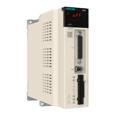
Veichi SD500 Series User manual

SD500 Spindle Servo Drive Manual
1
Preface
First of all, we’d like to extend out sincere thanks for purchasing SD500 series
spindle servo drive from Veichi Electric!
SD500 series spindle servo drive is designed with high performance closed-loop
vector control, featuring wide speed range, fast response, accurate positioning, etc. Its
various functions and external extension interfaces, with the upper CNC system, are
enough for spindle orientation, C-axis, rigid tapping, indexing and positioning. The
SD500 series spindle servo drive can be widely used in machining center, CNC
machine tool, CNC milling machine, tilting lathe and flying shear, chasing cut, etc.,
becoming the preferred drive product for various machine tool power axis.
This user manual of SD500 spindle servo drive provides product safety
information, mechanical and electrical installation instructions, basic commissioning,
troubleshooting and daily maintenance-related matters. To ensure correct installation
and operation of the SD500 spindle servo drive and full use of its superior
performance, please read this in detail before installing it. If there are any doubts
about functions and performance, please consult our technical support staff for
assistance.
Due to the continuous improvement of servo products, the information provided
here is subject to change without notice.

SD500 Spindle Servo Drive Manual
I
Catalog
Chapter 1 General.................................................................................................................... 1
1.1 Safety Precautions ........................................................................................................... 1
1.2 Pre-Use............................................................................................................................. 2
1.3 Technical Specification ................................................................................................... 4
Chapter 2 Mechanical and Electrical Installation............................................................ 6
2.1 Mechanical Installation ................................................................................................... 6
2.2 Electrical Installation....................................................................................................... 8
Chapter 3 Keyboard Layout and Operating Instructions............................................. 20
Chapter 4 Parameter Table.............................................................................................. 22
4.1 Parameter Mark Description......................................................................................... 22
4.2 Parameter List................................................................................................................ 22
4.3 Group F00: Environmental Applications ..................................................................... 23
4.4 Group F01: Basic Settings ............................................................................................ 24
4.5 Group F02: Motor 1 Parameter..................................................................................... 29
4.6 Group F03: Vector Control ........................................................................................... 35
4.7 Group F05: Input Terminal ........................................................................................... 40
4.8 Group F06: Output Terminal ........................................................................................ 46
4.9 Group F07: Running Control........................................................................................ 52
4.10 Group F10: Protection Parameters ............................................................................. 56
4.11 Group F11: Operator Parameters................................................................................ 63
4.12 Group F12: Communication Parameters.................................................................... 66
4.13 Group F15: Position Control....................................................................................... 69
4.14 Group F24: Spindle Control ....................................................................................... 72
4.15 C0x Group: Monitoring Parameters........................................................................... 75
4.16 Terminal Input / Output Function Selection............................................................... 77
4.17 Fault And Warning Code List ..................................................................................... 79
Chapter 5 Spindle Function Application Guidance ....................................................... 82
5.1 Motor Self-Learning...................................................................................................... 82

SD500 Spindle Servo Drive Manual
II
5.2 Speed Control ................................................................................................................ 84
5.3 Position Control............................................................................................................. 88
5.4 Spindle Orientation........................................................................................................ 90
5.5 Common Faults And Problems Explanation................................................................ 93
Chapter 6 Inspection, Maintenance and Warranty .......................................................... 98
6.1 Inspection....................................................................................................................... 98
6.2 Maintenance................................................................................................................... 99
6.3 Product Warranty........................................................................................................... 99
Appendix ............................................................................................................................... 100
Appendix I: Modbus Communication Protocol............................................................... 100
Appendix II: Matching Cable Description....................................................................... 101

SD500 Spindle Servo Drive Manual
1
Chapter 1 General
1.1 Safety Precautions
To ensure safety and proper use of this product, please fully understand the safety precautions described in this manual before using the
product.
Warning signs and meanings
The following marks are used in this manual to indicate that the place is important regarding safety. Failure to observe these precautions
may result in personal injury or even death and damage to this product and associated systems.
Danger: major safety accidents or death may be caused due to wrong operation.
Note: minor injuries may be caused due to wrong operation.
Table 1-1
Operation qualifications
This product must be operated by trained professionals. Moreover, the operator must be trained with professional skills, installation
methods, wiring, operation and maintenance of the equipment, and proper solutions to various emergencies that may arise during running.
Security guidance
The warning signs are presented to prevent injury to the operator and damage to this product and associated systems; please read this
manual carefully before use and follow the safety rules and warning signs strictly.
●Proper transportation, storage, installation, and careful operation and maintenance are essential to the safe operation of the spindle
drive. During transportation and storage, the spindle drive must be protected from shock and vibration, and must be stored in a dry
place free of corrosive gases, conductive dust, and ambient temperature lower than 60°C.
●This product carries a hazardous voltage and it controls a potentially hazardous motion mechanism. Failure to comply with the
regulations of this manual may result in personal injury or death and damage to this product and associated systems.
●Do not perform wiring work while the power is on, as there is a risk of death by electric shock. Before wiring, inspection,
maintenance, etc., cut off the power to all associated equipment and make sure the DC voltage of the main circuit has dropped to a
safe level and wait for 5 minutes.
●The power cable, motor cable and control cable must be connected tightly, the grounding terminals must be grounded effectively, and
the grounding resistance is lower than 10Ω.
●Human static electricity can seriously damage internal sensitive devices. Before performing related operations, please observe the
measures and methods specified in the electrostatic preventive measures (ESD), otherwise the spindle drive may be damaged.
●Since the spindle drive output voltage is in a pulse waveform, be sure to remove or move it to the output side if there is a capacitor or
varistor against lightning installed on the spindle drive’s input side.
●Do not install switching devices such as circuit breakers and contactors on the output side of the spindle drive (if a switching device
must be connected on the output side, the output current of the spindle drive must be 0 when the switch is operated).
●Failure at any point in the control equipment may result in production stoppage and major accidents. Therefore, please take the

SD500 Spindle Servo Drive Manual
2
necessary external protection measures or backup devices.
●This product should be used only for the purposes specified by the manufacturer, and must not be used in special areas such as
emergency, rescue, marine, medical, aviation, nuclear facilities, etc. without permission.
●Maintenance of this product should only be performed by Veichi or professionals authorized by Veichi. Unauthorized modifications
and use of parts that are not approved by Veichi may result in product failure. During maintenance, any defective device must be
replaced timely.
●Veichi are not responsible for any injury or damage to equipment on customers’ side or secondary customers if these operating
instructions are not complied with.
1.2 Pre-use
When receive the ordered products, please check the outer packaging to see if it is damaged, then open the outer packaging and confirm
that the spindle drive has no seeable damage, scratches or dirt (damage caused on the product during transportation does not belong to the scope
of our "three packages"). If you receive a product with shipping damage, please contact us or the shipping company immediately. And at last,
please confirm that the spindle drive model you received is the same as what you ordered.
1.2.1 Spindle Servo Drive Model and Nameplate Description
Figure 2-1

SD500 Spindle Servo Drive Manual
3
SD 500 -5R5 D - P B
SD:servo product
code
500: spindle servo series
Rated power
004:4kW;5R5:5.5kW;7R5:7.5kW;011:11kW;
015:15kW;018:18.5kW;022:22kW;030:30kW;037:37kW
Rated voltage
D:380V AC
Drive type
P:pulse type
L:MECHATROLINK-III bus type
E:EtherCAT bus type
Encoder type
B: incremental
square wave
Z: incremental
sine-cosine type
Figure 1-3
Rated output current of spindle servo drive
Input voltage
380V
Model
Rated input current (A)
Rated output current (A)
Motor power(kw)
SD500-004D-*
12.0
10.0
4.0
SD500-5R5D-*
14.6
13.0
5.5
SD500-7R5D-*
21.5
17.0
7.5
SD500-011D-*
27.0
25.0
11.0
SD500-015D-*
35.2
32.0
15.0
SD500-018D-*
45.3
38.0
18.0
SD500-022D-*
50.0
45.0
22.0
SD500-030D-*
67.7
60.0
30.0
SD500-037D-*
83.4
75.0
37.0
Table 1-2

SD500 Spindle Servo Drive Manual
4
1.2.2 Motor Naming Rules
CM 2 S-1560 D 004-U2 28 N 3 Y
Spindle motor series
Base
A:130;0:165;
1:180;2:200;
4:265;6:360;
Body length
S,M,L,H,E,F
Reference speed
1560:1500rpm
Rated voltage
D:380V
Rated power
004:4kW; 5R5:5.5kW; 7R5:7.5kW; 011:11kW;
015:15kw; 018:18.5kW; 022:22kW; 030:30kW; 037:37kW
Motor shaft
diameter
28:28mm
38:38mm
Shaft structure
K:motor shaft with
flat key
N:motor shaft
without flat key
Installation
method
3:horizontal
5:vertical
7:horizontal-
vertical
Max. speed
60:6000rpm
Encoder type
U0:no encoder
U1:incremental 1024 lines
U2: incremental 2500 lines
Z1:sine-cosine 1024 lines
Temperature
sensor
Empty:none
Y:KTY;
C:PTC;
Figure 1-3
1.3 Technical Specification
Item
Description
Power input
Voltage & frequency
Three-phase:380V~440V, 50/60Hz
Allowable fluctuation
Voltage imbalance rate:<3%; frequency: ±5%; distortion rate in
accordance with IEC61800-2
Closing surge current
Lower than rated current
Power factor
≥0.94 (with DC reactor)
Spindle drive efficiency
≥96%
Output
Output voltage
Output under rated conditions: three-phase 380 to 440V, error less than
5%
Output speed range
4-pole motor 0~18000rpm; 0~600Hz
Main control
performance
Motor control mode
Sine wave PWM modulation, fully closed-loop vector control
Speed control range
1:1000
Steady-state speed accuracy
≤0.05% rated synchronous speed
Starting torque
200% rated torque at 0Hz
Torque response
<10ms
Speed control accuracy
±0.2%
Position control accuracy
±1pulse
Overload capacity
200% rated current for 20S
Input/output
interface
Digital input
7-way optocoupler isolated input, input method NPN or PNP optional
Digital output
2-way optocoupler isolated output
Analog input
2-way: -10Vto +10V, 0 to 10V, 0 to 20mAselectable
Analog output
1-way:0~10V、0~20mAOptional
Relay output
2-way: two sets of normally open and normally closed contacts
Encoder input interface
2-way: motor encoder 1 way; spindle encoder 1 way
Encoder output interface
1-way: crossover output
Pulse input interface
1-way: orthogonal pulse/direction + pulse/CW+CCW
Bus interface
None

SD500 Spindle Servo Drive Manual
5
Spindle
function
Speed control
Range: 0~12000RPM;
Directional control
±1 pulse accuracy; set 8 positions with terminals
Rigid tapping
Connectable to a variety of imported and domestic systems with 2%
tapping error
Encoder self-learning
Dual encoders automatically learn directions without wiring adjustments
One-touch zero setting
One touch to set any position as zero point
Arbitrary crossover output
1 to 32767 arbitrary crossover output selection
Others
C-axis control, thread cutting, electronic gear, borehole, zero- speed lock
Protection
Protection against overvoltage, undervoltage, current limit, overcurrent,
overload, overheat, overvoltage stall, input and output phase loss, and
stall, data protection, electronic thermal relay
Environment
Installation site
Altitude below 1,000 metres, if use above 1,000 metres requires a
derating of 1% for every 100 metres of elevation;
No condensation, icing, rain, snow, hail, etc., solar radiation below
700W/m2, air pressure 70 to 106kPa
Temperature & humidity
-10~+50 ℃, if derate above 40 ℃, max. of 60 ℃ (no-load running)
5%~95%RH (no condensation)
Vibration
When 9~200Hz,5.9m/s2(0.6g)
Storage temperature
-30~+60℃
Installation method
Wall-mounted, vertical -mounted
Protection level
IP20
Cooling method
Forced air cooling
Table 1-3

SD500 Spindle Servo Drive Manual
6
Chapter 2 Mechanical and Electrical Installation
To ensure safety during use of the product and to give play to the maximum performance of the spindle drive, please use the product in strict
accordance with the environmental, wiring, and ventilation requirements described in this chapter.
2.1 Mechanical Installation
2.1.1 Spindle Drive External Dimensions
Mounting hole
Drive model
External dimensions(mm)
Mounting Dimension(mm)
Mounting
aperture
W
H
H1
D
D1
W1
W2
H2
A
B
SD500-004D-*
100
242
231
156
149
84
86.5
231.5
8
5.5
3-M4
SD500-5R5D-*
SD500-7R5D-*
116
320
307.5
176
169
98
100
307.5
9
6
3-M5
SD500-011D-*

SD500 Spindle Servo Drive Manual
7
W1
W2
H1
D
H
H2
W
A
B
Mounting hole
D1
Inverter model
External dimensions(mm)
Mounting dimension(mm)
Mounting
aperture
W
H
H1
D
D1
W1
W2
H2
A
B
SD500 -015D-*
145
424.5
387
242
236
100
100
411.5
23
8
4-M5
SD500-018D-*
SD500-022D-*
SD500-030D-*
185
471
433
242
236
140
140
457
22
8.75
4-M6
SD500-037D-*
Figure 2-1
2.1.2 Installation Environment and Precautions
a) Environment temperature: the surrounding environment temperature has a great impact on the lifespan of the spindle servo drive, so it must
not exceed the allowable temperature range (-10℃~50℃), and when the environment temperature exceeds 40℃, the external forced heat
dissipation and the drive must be derated to use.
b) Humidity should be below 95% and no condensation of water droplets at the site. Avoid applications with direct sunlight, oil, dust or metal
dust.
c) Thin air above 1000m will lead to poor heat dissipation, so please derate to use it. Derate by 1% for every 100m of elevation.

SD500 Spindle Servo Drive Manual
8
d) The spindle drive needs to be mounted on a flame-retardant surface to ensure enough space for heat dissipation. The mounting surface needs
reliably bear the weight of the spindle servo drive, otherwise there is a possibility of personnel injury or equipment damage if it falls.
e) When the spindle drive is installed near a vibration source, please install vibration isolators on the mounting surface of the servo unit to
prevent vibration from being transmitted to the servo unit.
f) Install the spindle servo drive away from sources of electromagnetic interference.
2.1.3 Spindle Drive Installation Space Requirements
Heat generated from SD500 spindle servo drive is distributed in a bottom-up way, the spindle servo drive must be installed in the following
vertical way (see Figure 2-1), and other components in the cabinet should be taken consideration to ensure that the SD500 spindle drive has
enough space for heat dissipation. Multiple spindle servo drives are usually installed side by side, and the installation space requirements are
shown in the figure below as well. In cases where the drives are mounted above or below, it is highly recommended to install thermal deflectors
between the drives.
Figure 2-2
2.2 Electrical Installation

SD500 Spindle Servo Drive Manual
9
2.2.1 Peripheral Electrical Components and Connections
Grounding
Input side
noise filter
Input side
noise filter
Electromagnetic
contactors
Earth leakage
circuit breakers
RE
ST U VW
AC reactor
AC380-440V
Three-phase power supply
Circuit
Breaker
Braking
resistor
Braking
unit
Grounding
+PB
CN1
C N2
CN6 RS485 \RS2 32
Co nv e rter
Motor encoder
Keyboard
PC
CNC
Analogue signal cable
I/O input and output signal cable
Spindle encoder
Figure 2-3
Note: When only one encoder is configured in the system, the spindle encoder signal terminal is invalid. The encoder signal must be connected
to the motor encoder signal terminal.
2.2.2 Description of Use of External Electrical Components
Accessory
Mounting position
Function description
Air circuit breaker
Front end of input circuit
It contacts and breaks the circuit and acts promptly to protect the downstream
equipment in case of short circuit or serious overload. Rated current of air
switch can be selected according to 150% of the rated current of the drive.

SD500 Spindle Servo Drive Manual
10
Electromagnetic
contactor
Between the air switch and the
spindle servo drive
Drive power-up control. Selected according to 150% of the drive's rated
current.
AC reactor
Spindle servo drive input side
Improve the power factor of the input side and the efficiency and thermal
stability of the whole spindle drive;
Effectively eliminate the influence of input-side high harmonics on the
spindle drive and reduce external conduction and radiation interference.
Selected according to 100% of the rated current of the drive.
Braking resistor
Models with 37kW and below
For models with 37kW or lower, please use the optional braking resistor, and
refer to the braking resistor matching table;
The motor consumes regenerative energy through the braking resistor during
decelerating.
Table 2-1
⚫select braking resistor
When the spindle drive with large inertia decelerates with load or for emergency, the motor is running under the discharge state, the load
energy through the inverter bridge to the spindle drive DC link, causing the spindle drive bus voltage to rise until it exceeds a certain limit, and
then the drive will report an overvoltage fault, to prevent which, those external braking components need to be installed. The following table
shows the typical reference values of external braking resistor specifications:
Spindle drive model
Min. allowable
braking resistance
Braking resistor
power
SD500-004D-*
50Ω
1.0kW
SD500-5R5D-*
50Ω
1.0kW
SD500-7R5D-*
45Ω
1.5kW
SD500-011D-*
35Ω
2.0kW
SD500-015D-*
30Ω
3.0kW
SD500-018D-*
30Ω
3.0kW
SD500-022D-*
25Ω
4.0kW
SD500-030D-*
18Ω
6.0kW
SD500-037D-*
18Ω
7.0kW
Table 2-2
The table is a typical reference data, the braking resistor needs to be determined according to the power generated by the motor in the
actual application system (but the braking resistance value cannot be lower than the limit in the table above), and the system inertia, deceleration
time, the energy of the bit energy load, etc. are related. The greater the inertia of the system, the shorter the deceleration time required, and the
more frequent the braking, the greater the power and the smaller the resistance value of the braking resistor needs to be. Users can choose
different resistor resistance and power according to the actual situations, please consult our technical support for detailed calculation.

SD500 Spindle Servo Drive Manual
11
2.2.3 Main Circuit Terminal Description
Figure 2-4
Terminal mark
Terminal name
Function description
R、S、T
Three-phase AC power input terminal, 380 ~ 440V,
50/60Hz
AC input three-phase power connection point
(+)、(-)
DC bus positive/negative terminals
Common DC bus input point or external brake unit
(+)、PB
Brake resistor connection terminal
Reserved terminal for external braking resistor
U、V、W
Spindle servo driver output terminal
Three-phase AC output connected to the motor
PE
Ground terminal
Power and motor ground terminal
Table 2-3
⚫Recommended cable size for main circuit connection:
Servo spindle drive model
Recommended cable size(mm2)
Terminal screw
specification
Recommended tightening
torque (N.m)
R/S/T U/V/W
PE
SD500-004D-*
4.0
4.0
M4
1.2~1.5
SD500-5R5D-*
6.0
6.0
M4
1.2~1.5
SD500-7R5D-*
6.0
6.0
M5
2~2.5
SD500-011D-*
10.0
10.0
M5
2~2.5
SD500-015D-*
10.0
10.0
M6
4~6
SD500-018D-*
16.0
16.0
M6
4~6
SD500-022D-*
16.0
16.0
M6
4~6
SD500-030D-*
25.0
25.0
M8
8~10

SD500 Spindle Servo Drive Manual
12
SD500-037D-*
25.0
25.0
M8
8~10
Table 2-4
Main circuit notes:
⚫The input side wiring of the spindle servo drive has no phase sequence requirement, and attention should be paid to the electrical
specifications of the power input.
⚫External power wiring specifications and installation methods need to comply with local regulations and relevant IEC standards
⚫The braking resistor is selected with reference to the recommended value and the wiring distance is shorter than 5m.
⚫The output side of the spindle servo drive must not be connected to capacitors or surge absorbers, otherwise it will cause frequent
protection or even damage to the spindle servo drive。
⚫Separate the motor cable, input power cable and control cable alignment.
⚫Please use ground wires of the diameter specifications in the technical standards for electrical equipment, and it should be as closer as
possible to the ground point, ground resistance at 4Ω or below. Do not share the ground wires with the welding machines or power equipment.

SD500 Spindle Servo Drive Manual
13
2.2.4 Pulse-type Control Circuit Wiring
SC
X1
X2
X3
X4
X5
X6
X7
24V of the system under low level
0V of the system under high level
27
11
26
41
10
25
40
39
TA1
TB1
TC1
TA2
TB2
TC2
Y1
COM
Y2
13
42
28
15
30
44
14
29
43
12
42
Internal 24V control power supply
Internal control power ground
+24V
COM
OZ-
20
5
19
4
Encoder output A+
Encoder output A-
Encoder output B+
Encoder output B-
Encoder output Z+
Encoder output Z-
Encoder output
(422 standard)
22
7
21
6
36
35
OA+
OA-
OB+
OB-
OZ+
Command pulse input A+/P+
Command pulse input A-/P-
Command pulse input B+/D+
Command pulse input B-/D-
A/P+
A/P-
B/D+
B/D-
GND
Analog public port
-10V~+10V input AI1
17
10V (50mA) power output +10V
2
0/2~10V or 0/4~20mA input AI2
16
0/2~10V or 0/4~20mA output AO
31
1
CN1
CN6A/B
Bus communication
interface
A1+
A1-
B1+
B1-
Z1+
Z1-
A2+
A2-
B2+
B2-
Z2+
Z2-
+5V
0V
Encoder power
Encoder
power ground
12
13
6
1
7
2
10
5
8
3
15
14
9
4
Motor encoder
input
Spindle encoder
input
T1
11
Motor thermal protection
CN2
CN1
Twin port
Three-phase AC380V
50/60Hz
R
S
T
PE
MCCB
( ) ( ) PB
Braking resistor
M
Forward running/stop
Reverse running/stop
Spindle orientation
Rigid tapping / pulse position
Zero-speed servo
Fault reset
Swing
Position in control
Drive ready
U
V
W
1/3/18/32
Orientated output
Drive fault
output
Note: means shielded twisted pair cables
Figure 2-5

SD500 Spindle Servo Drive Manual
14
⚫Control signal function description
Category
Terminal mark
Terminal name
Definition of terminal functions
Power
supply
+5V-DGND
External +5V power supply
Encoder power supply with terminals, encoder power supply
maximum output current: 300mA
+10V-GND
External +10V power supply
Provide +10V power supply, maximum output current: 50 mA.
Generally used as the power supply for external potentiometer,
potentiometer resistance range: 1KΩ ~ 5KΩ
+24V-COM
External +24V power supply
External +24V power supply, generally used as power supply
for digital input/output terminals and external sensor Maximum
output current: 100 mA
Analog
AI1-GND
Voltage-type analog input
1. Input range: AI1: -10V~+10V; AI2:0~10V/0~20mA, default
by voltage-type input, setting by function code P05.42.
2. Input impedance: voltage-type input impedance 20kΩ,
current type input impedance 500Ω.
AI2-GND
Voltage or current-type analog
input
AO-GND
Voltage or current-type analog
output
Output range: voltage 0~+10V or current 0~20mA, default by
voltage-type output, setting by function code P06.00.
Digital
Input
X1、X2
X3、X4
X5、X6
X7、SC
Switching input, high-speed input
1.Input impedance: 4.4 KΩ
2. Voltage range at level input: 10 ~ 30V
3. Bidirectional input terminal for both NPN and
PNP connection.
4. X7 can be used as a high-speed pulse input channel with a
maximum input frequency of 100 kHz in addition to the
features of X1 to X6. 5.
5.All of them are programmable digital input terminals.
terminal function setting via the function code.
A+/A-
B+/B-
Z+/Z-
Spindle incremental encoder input
Only for RS-485 standard differential signal transmitter signal
PULS+/PULS-
SIGN+/SIGN-
Position command signal
Only for RS-485 standard differential signal transmitter signal
Digital
output
Y1+/COM
Y2+/COM
Switching output 1, 2
Optocoupler isolation, open collector output
1.Output voltage range: DC 0V~30V
2.Output current range: DC 0mA~50mA
TA1/TB1/TC1
TA2/TB2/TC2
Relay output 1, 2
TA1-TC1/ TA2-TC2: normally open;
TB1-TC1/ TB2-TC2: normally closed;
Contact capacity: 30VDC/1A
OA+/OA-
OB+/OB-
OZ+/OZ-
Encoder crossover output
Differential output, the receiver needs to use RS-485 standard
differential signal receiver
Table 2-5
2.2.5 Wiring Terminal Pin Definition
Figure 2-6
● CN1 multi-function control terminal pin definition:
1
15
16
30
44 31

SD500 Spindle Servo Drive Manual
15
CN1 multi-functional terminal interface
Pin No.
Signal name
Function
Pin No.
Signal name
Function
1
AGND
Analog GND
23
-
-
2
10V+
Internal 10V,100mA
24
-
-
3
AGND
Analog GND
25
X5
Multi-function contact input 5
4
SIGN-
Command direction-
26
X2
Multi-function contact input 2
5
PULS-
Pulse command-
27
SC
I/O public terminal+
6
OB-
Crossover output OB-
28
Y2+
Open collector output 2+
7
OA-
Crossover output OA-
29
TB2
Relay B2
8
-
-
30
TB1
Relay B1
9
-
-
31
AO1
0~10V, 0~20mA optional
10
X4
Multi-function contact input 4
32
AGND
Analog GND
11
X1
Multi-function contact input 1
33
DGND
Digital GND
12
24V+
Internal 24V,100mA
34
DGND
Digital GND
13
Y1+
Open collector output 1+
35
OZ-
Crossover output OZ-
14
TA2
Relay A2
36
OZ+
Crossover output OZ+
15
TA1
Relay A1
37
-
-
16
AI2
0~10V, 0~20mA optional
38
-
-
17
AI1
-10V~+10V
39
X7
Multi-function contact input 7
18
AGND
Analog GND
40
X6
Multi-function contact input 6
19
SIGN+
Command direction +
41
X3
Multi-function contact input 3
20
PULS+
Pulse command +
42
COM
Internal +24V power to ground
21
OB+
Crossover output OB+
43
TC2
Relay C2
22
OA+
Crossover output OA+
44
TC1
Relay C1
Table 2-6
● CN2 multi-function control terminal pin definition:
1
2
3
4
5
11
12
13
14
15
6
7
8
9
10
Figure 2-7
CN2 encoder interface
Pin No.
Signal name
Function
Pin No.
Signal name
Function
1
U-
Spindle encoder signal A-
8
A+
Motor encoder signal A+

SD500 Spindle Servo Drive Manual
16
Pin 8
Pin 1
Pin 8
Pin 1
CN6A
CN6B
2
W-
Spindle encoder signal Z-
9
B+
Motor encoder signal B+
3
A-
Motor encoder signal A-
10
V+
Spindle encoder signal B+
4
B-
Motor encoder signal B-
11
T1
Motor overheating
5
V-
Spindle encoder signal B-
12
5V
Motor encoder power supply
5V
6
U+
Spindle encoder signal A+
13
0V
Motor encoder power supply
0V
7
W+
Spindle encoder signal Z+
14
Z-
Motor encoder signal Z-
Housing
Shielded
-
15
Z+
Motor encoder signal Z+
Table 2-7
Note: If the system is equipped with only one encoder, the spindle encoder signal terminal is invalid, and the encoder signal must be
connected to the motor encoder signal terminal.
Figure 2- 8
● CN6 network terminal pin definition:
CN6A/CN6B interface definition
Pin No.
Signal name
Function
Pin No.
Signal name
Function
1
GND
Signal ground
6
-
-
2
-
-
7
485-
485 data-
3
GND
Signal ground
8
485+
485 data +
4
+5V
External keyboard
power supply
Housing
Shielded
Shielded
5
+5V
Table 2-8
2.2.6 Control Circuit Wiring Instructions
◆AI analog input circuit:
SD500 spindle servo provides two analog input interfaces AI1 (-10~+10V) and AI2 (0~+10V or 0~20mA). Since the weak analog signals
are susceptible to external interference, the wiring control cables should be sufficiently far away from the main circuit and strong power cables
(including power cables, motor cables, relays, contactor connection cables, etc.) for more than 30cm and avoid parallel placement. The
connection cable is strongly recommended to use twisted shielded pair cables, and the cable shielding layer should be reliably connected to the
drive terminal housing, and the wiring distance should be as short as possible. In some cases where the analog signal is subject to serious
interference, a ferrite magnet ring can be added near the driver end. The following diagram shows the analog input terminal wiring diagram:

SD500 Spindle Servo Drive Manual
17
◆
17 AI1
1 GND
16 AI2
Controller Servo drive
FG
Please connect the
shielded cable as
required
twisted pair
18 GND
about
66kΩ
about
20kΩ
Figure 2-9
◆Digital input terminal wiring:
The digital input terminals X1 to X7 support either drain or source wiring. The following is an example of X1, and interface circuit for X1
to X7 are all the same. The following is an example of wiring through a relay or transistor circuit (drain or source wiring). When using a relay
connection, select a relay for microcurrent. If there is no such a relay for microcurrent, it may cause poor contact.
a) Drain-type wiring
11 X1
External
power
24VDC
SD500 control
terminal CN1
27 SC
• •
4.7KΩ
Drain-type wiring method
12
42
+24V
COM
NPN
Figure 2-9
b) Source-type wiring
11 X1
External power
24VDC
SD500 control
terminal CN1
27 SC
• •
4.7KΩ
Source-type wiring
method
12
42
+24V
COM
PNP
Figure 2-10
Table of contents
Other Veichi Servo Drive manuals
Popular Servo Drive manuals by other brands

SMC Networks
SMC Networks LESYH Series Operation manual

Advanced
Advanced QUICKSTART BR2303NI-A01-DC080 user manual

Allen-Bradley
Allen-Bradley Kinetix 6000 Design guide

Danfoss
Danfoss VLT Integrated Servo Drive ISD 510 System operating instructions

Fuji Electric
Fuji Electric Alpha 5 Installation and Wiring

INGENIA
INGENIA Earth EAR-3/40-C-P product manual