A&D RA3100 Omniace User manual

RA3100
Omniace
Communication command
Instruction Manual
1WMPD4004790

CAUTION
(1) Turn off the power when an error occurs with the product.
If it is not possible to trace the cause of a problem, please contact our sales representative.
(2) The contents of this manual are subject to change without notice.
(3) This manual is copyrighted with all rights reserved. This manual may not be reproduced, modified, or
translated without the written permission of A&D Company, Limited. No parts of this manual may be
transcribed without permission.
(4) Please let us know if any points are unclear or missing in this manual.
(5) A&D Company, Limited. will not be held responsible for any damages or loss of income caused by the
operation of this device or any direct, indirect, special, or inevitable damages caused by defects in the
product, even if there is notice that the corresponding damages may occur. We will also not be held
responsible for any third-party claims of rights. At the same time, we will not be held responsible for any
loss of data. We will not be held responsible for any issues that arise that are caused by problems with
the manual.
2022A&D Company,Limited.
Omniace is a registered trademark of A&D Company, Limited.
Microsoft, Windows and Windows 10 IoT are trademarks or registered trademarks of Microsoft
Corporation in the United States and other countries.
Software owned by Adobe Corporation in the United States is used based on the SIL Open Font License.
Product names and company names in this manual are trademarks or registered trademarks of their
respective owners in Japan and other countries.

Introduction
1WMPD4004269A 3
Introduction
We thank you for your purchase of our data acquisition product
OMNIACE RA3100 (hereinafter "the RA3100" or "this product").
This instruction manual explains how to use the communication interface
and the communication commands when controlling communication
using the LAN interface or the RS-232C interface.
Please read this manual carefully to use this product correctly before
using this product.
Please read this instruction manual, which is provided on the included CD, as it gives details of the
functions and operations of the input module and the RA3100. Concerning the operation of the host
computer connected to the interface, please read the corresponding manual that should be provided
with the host computer.
If you have questions or are unsure of the instructions given in this manual, please contact us.
<Instruction manual>
Name
Descriptions
RA3100 instruction manual Operations and settings of parameters for RA3100 are described.
Symbols in This Manual
Terms and symbols used in this manual denote as follows.
WARNING
This indicates a condition or practice that could result in personal injury or loss of life,
or may result in light injury or physical damage if this equipment is misused due to
neglect of a Warning.
CAUTION
This indicates a condition or practice that could result in light injury or damage to the
equipment or other property if this equipment is misused due to neglect of a Caution.
Note
This indicates a condition or practice that could result in incorrect operation or damage to
data if this equipment is misused due to neglect of a Note, as well as measurement
limitations and additional explanations.
Reference page
A tap is the act of lightly touching an item such as a key displayed on the screen with a
finger. Example: Used for selecting or setting screen keys.
__ key Enclosed characters represent a key name on the operation panel.
Example: START key
__ key Text enclosed in __ indicates touch panel keys displayed on the screen.
Example: CH key
[__] screen Text enclosed in [__] indicates the text of items on the screen.
Example: [Module 1]
k (lower case)
K (upper case)
Example: 1 kg = 1000 g
1 KB = 1024 bytes

Table of contents
4 1WMPD4004269A
Contents
Introduction ........................................................................................................................................................ 3
<Instruction manual> ..........................................................................................................................................3
Symbols in This Manual......................................................................................................................................3
Communication settings........................................................................................................................ 6
Preparing the product.....................................................................................................................6
Connections of communication ports .....................................................................................6
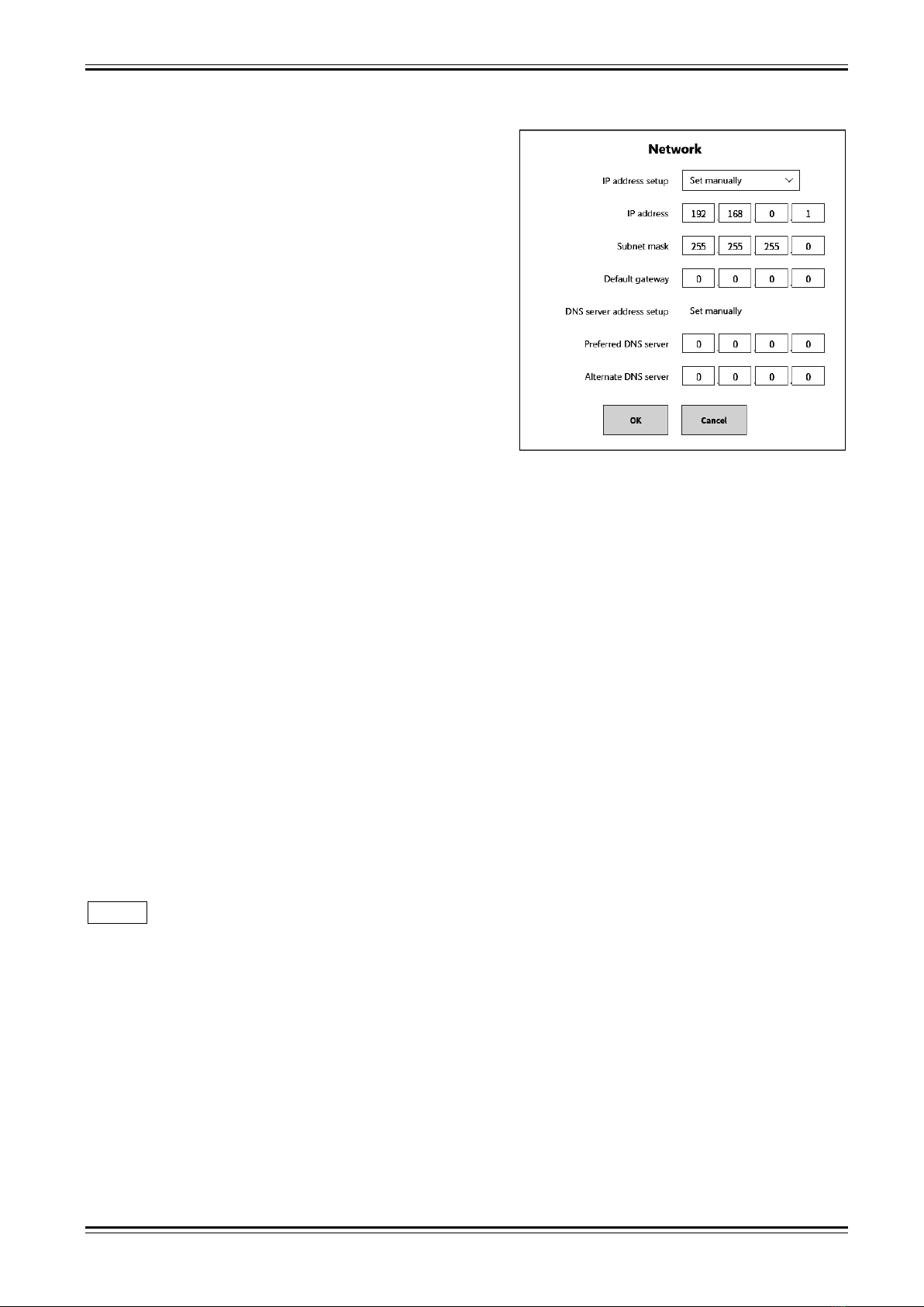
Network setup for LAN port ....................................................................................................7
Communication parameters of RS-232C (COM port ) ...........................................................9
Overview of communication commands ............................................................................................. 10
Communication format .................................................................................................................10
Command format..................................................................................................................10
ACK and NAK.......................................................................................................................10
Communication protocol.......................................................................................................12
Command List ..............................................................................................................................13
Command groups .................................................................................................................13
Command List ......................................................................................................................13
Details of command ............................................................................................................................ 15
Settings of main unit ( Scommands) ...........................................................................................15
S01: Setting common recording format ................................................................................15
S02: Setting recording format using memory .......................................................................17
S03: Setting recording format using SSD .............................................................................19
S04: Setting recording format using printer ..........................................................................20
S21: Setting start-trigger format
( using analog input signal)
........................................................21
S22: Setting start-trigger format
( using digital input signal)
.........................................................22
S24: Setting memory-trigger format
( using analog input signal)
..................................................23
S25: Setting memory-trigger format
( using logical input signal)
..................................................24
S26: Setting format of memory-trigger mode........................................................................25
S30: Setting format of channel display .................................................................................26
S31: Setting display format of logical input signal ................................................................28
S32: Setting format of physical quantity conversion.............................................................30
S33: Setting format of unit list...............................................................................................31
S34: Setting recoding name .................................................................................................32
S35: Setting thumbnail monitor.............................................................................................33
S36: Setting parameters to print out .....................................................................................34
S37: Setting header, footer and annotation ..........................................................................35
S38: Setting speed to feed recording paper .........................................................................36
S39: Setting Y-T waveform monitor ......................................................................................37
S40: Setting X-Y waveform...................................................................................................38
S41: Setting X-Y waveform channel .....................................................................................39
S42: Setting FFT analysis.....................................................................................................40
S43: Partition settings of waveform monitor .........................................................................43
S44: Setting field length ........................................................................................................44
S45: Setting recording information XML file output ..............................................................44
S46: Setting number of partitions .........................................................................................45

Table of contents
1WMPD4004269A 5
Module setting ( Mcommands) ....................................................................................................46
M01: Module setting two channel voltage (RA30-101).........................................................46
M02: Module setting four channel voltage (RA30-102) ........................................................47
M03:
Module setting two channel high-speed voltage (RA30-103)
...........................................48
M05:
Module setting 16 channel logic
(RA30-105) ...................................................................49
M06:
Module setting two channel temperature
(RA30-106).......................................................50
M12:
Module setting remote control
(RA30-112) ......................................................................52
Reading information ( Icommands).............................................................................................54
I00: Reading information of main unit, type, serial No. ........................................................54
I04: Reading board information of input module ..................................................................54
I05: Reading the status of main unit ....................................................................................55
Execution process ( Ecommands)...............................................................................................56
E01: Execute canceling the input offset ( zero-cancel) ........................................................56
E07: Execute start and end recording ..................................................................................56
E15: Execute adjust paper feed............................................................................................57
E16: Execute print header, footer and annotation ................................................................57
Specifications of hardware.................................................................................................................. 58
LAN port .......................................................................................................................................58
COM port......................................................................................................................................58

1. Communication settings -1.1.Preparing the product
6 1WMPD4004269A
HUB HUB
Communication settings
The RA3100 is equipped with an interface with a LAN port and a COM port (RS-232C), which are used to
connect to peripherals.
LAN port is 1000BASE-T, 100BASE-TX and 10BASE-T in accordance with IEEE802.3.
Cables conforming to the relevant standards of the connections should be used.
Use crossover cables when directly connecting to a computer using RS-232C.
Preparing the product
Connections of communication ports
The interface is mounted on the rear panel of the RA3100. Connect a cable to the LAN port when using
ethernet. Connect a cable to the RS-232C when using COM port.
Rear panel of RA3100 Interface
LAN port COM port
LAN cable RS-232C cable
(RJ45) (D-sub 9 pins)
Connection using LAN cable
RA3100

1. Communication settings -1.1.Preparing the product
1WMPD4004269A 7
Modem
Connection using RS-232C cable
(Crossover cable)
RA3100 (Straight through cable)
Computer
Use crossover cable when connecting to computer, DTE device and others using RS-232C.
Use straight through cable when connecting to DCE device.
Network setup for LAN port
This section describes for setup of LAN port.
The current settings are displayed by the following procedure.
Step 1 Tap Setup key of the "side menu" on the display block.
Step 2 Tap Environment key of "Main unit setup" item of the [Setup] screen.
Step 3 Tap the network Edit key on the [Comm.] setup screen.
Network settings
RS-232C settings
When tapping the network Edit key, the network setup dialog box is displayed.
Consult a network manager for the settings when connecting to an ethernet network.

1. Communication settings -1.1.Preparing the product
8 1WMPD4004269A
(1)
IP address setup:
Select whether to "obtain automatically" or "set manually".
When "obtain automatically" is selected, IP address is
set automatically by the DHCP server on the network.
Then, the address of the DNS server is set automatically
because automatic setup of the DNS server is enabled.
When "set manually" is selected, IP address, subnet
mask, gateway and DNS server address needs to be set
manually.
(2)
IP address:
Specify an IP address that is a unique number on the
network and consists of a network address +device
address if "obtain automatically" is selected.
Network setup dialog box
(1)
(2)
(3)
(4)
(5)
(6)
Example:
IP address of the RA3100 is set to "192.168.0.1". IP address of computer is set to "192.168.0.10".
(3) Subnet mask:
The value that defines the IP address range (subnet).
In the case of "192.168.0.1", the subnet mask should be set to "255.255.255.0".
(4) Default gateway:
Sets the IP address of the gateway device for connecting the network that the product is connected to
with external networks.
(5) Preferred DNS server:
Sets the IP address of the preferred DNS server on the network. The DNS server converts automatically
domain name to IP address.
(6) Alternate DNS server:
Sets the IP address of the alternate DNS server on the network.
Note
Specify port number "3000" when using the LAN port to communicate with an external device.

1. Communication settings -1.1.Preparing the product
1WMPD4004269A 9
Communication parameters of RS-232C (COM port )
The current settings are displayed by the following procedure.
Step 1 Tap Setup key of the "side menu" on the display block.
Step 2 Tap Environment key of "Main unit setup" item of the [Setup] screen.
Step 3 Tap the [RS-232C] Edit key on the [Comm.] setup screen.
When using the RS-232C port of this product to communicate with an external device, match the RS-
232C settings with those of the host device.
(1)
Baud rate:
Sets the RS-232C data transmission speed.
300 / 600 / 1200 / 2400 / 4800 / 9600 / 14400 / 19200 /
38400 / 57600 / 115200 / 230400 / 460800 bps
(2)
Data bits:
The number of bits in one byte of data. Fixed to 8 bits.
(3)
Stop bits:
The stop bits in one byte of data. Select 1 or 2 bits.
RS-232C setup dialog box
(1)
(2)
(3)
(4)
(5)
(4) Parity:
The parity bit for one byte of data.
None, odd, even, mark, or space
(5) Flow control:
The flow control of communication using CTS/RTS.
None, Xon/Xoff, or Hardware

2. Overview of communication commands -2.1.Communication format
10 1WMPD4004269A
Overview of communication commands
When this product is connected to a host machine via LAN or RS-232C and receives a command from
the host machine, it executes the process according to the command. LAN is TCP/IP socket
communication, and RA3100 communicates as a server.
CAUTION
When communicating, there is no particular distinction between LAN or RS-232C communication
ports, and processing is performed when a command is received. However, if commands are
received from both ports at the same time, it may cause malfunctions to occur, so only one of the
communication ports should be used.
Use ASCII and UTF-8 codes for communication of the RA3100.
Characters of JIS, SJIS, EUC codes and others become a garbled text.
Communication format
Command format
The string of the command consists of 3-character command, parameter strings and delimiter.
Command and parameter strings are separated with a space [0x20].
Multiple parameters are separated with comma "," [0x2C].
Place CR [0x0D] and LF [0x0A] delimiters at the end of a command.
Enclose the string parameter of a signal name etc. with STX [0x02] and ETX [0x03].
Use ASCII and UTF-8 codes for the string parameter of a signal name etc.
Place a comma "," [0x2C] when omitting a parameter.
Place CR [0x0D] and LF [0x0A] delimiters when omitting a parameter and the strings after that parameter.
Exponential, decimal and integer notation can use when exponential notation is used in a parameter
description.
Format:
Command (3-characters)
(SP)
Parameters P1, P2, • • •
Delimiter (CR)(LF)
Example:
S01(SP)0,1,0,60000(CR)(LF)
S30(SP)1,1,(STX)SIG-NAME(ETX),1,50,50,-100,100,1(CR)(LF)
ACK and NAK
When command is received and is performed correctly, ACK [0x06] (Acknowledgement) is responded.
When an error occurs in receiving or performing command, NAK [0x15] (Negative Acknowledgement) is
responded.
ACK (Normal response)
Format1: Standard ACK
ACK (3-characters)
(SP)
Command (3-characters)
Delimiter (CR)(LF)
Command name is responded if correct process.

2. Overview of communication commands -2.1.Communication format
1WMPD4004269A 11
Format2: ACK with data
ACK
(SP)
Command
(,)
Reponse1, response2, • • •
(CR)(LF)
Processing with output information returns that information as response output.
Multiple outputs are separated using a comma ",".
Format3: ACK with binary data
ACK
(SP)
Command
(,)
Size
(,)
Binary data
(CR)(LF)
When output data is binary, data size (byte length of data) is added to output response data.
Serial communication of RS-232C does not output binary data.
NAC (Error response)
When a command can be received correctly but cannot be performed, NAK is responded.
Format:
NAK(3-characters)
(SP)
Command
(,)
Error number
(,)
Parameter number
(CR)(LF)
The first three characters are the NAK of the error response, then the separator (SP) is placed, and
then the three characters of the command name, error number, and parameter number where the
error occurred are output. Each item is separated by a comma (,).
When a command cannot be identified, an alternative header is output instead of a command name.
Alternative header:
Header
Descriptions
HAD
3-character command could not be recognized.
DEL
Delimiter could not be recognized within default length of receiving data.
FMT
Syntax error.
BSY
Command busy status.
Error number:
Error number and descriptions are as follows:
When an error occurs, the following error numbers are replied as a parameter of NAK.
( ) means system error inside of the RA3100.
Error number
Descriptions
1
Command busy.
2
Settings cannot be changed because recording is continued.
3
Unknown command.
4
Parameter is out of range.
5
Number of parameters is incorrect.
6
Time out.
7
(Unknown device)
8
(Common memory error)
9
Deficiency of required parameter.
10
Storage device has been filled.
11
Full memory.
12
(Internal bus error)
13
Execution failure.

2. Overview of communication commands -2.1.Communication format
12 1WMPD4004269A
Parameter number:
Parameter number shows which parameter in receiving command has failed.
"-1" is replied to parameter number if it cannot be identified.
Communication protocol
When the host computer sends a command and the RA3100 has received, ACK or NAK is replied to the
computer. Send next command from the host computer after receiving and confirming them.
Host computer RA3100
Send command
Processing
Proper processing?
Y
Waiting
Receiving
N
Reply?
NAK
ACK
E
rror treatment
N
ext process

2. Overview of communication commands -2.2.Command List
1WMPD4004269A 13
Command List
First character of 3-character command shows type of command. Other characters show content of
command.
Example : S04 S : S command 04 : Settings of recording printer
Command groups
Types of command are as follows:
First character
Descriptions
Details
S
Scommand : Settings of main unit
3.1. Settings of main unit
M
Mcommand : Settings of modules
3.2 Settings of modules
I
Icommand : Reading information
3.3 Reading informations
E
Ecommand : Execution process
3.4 Execution peocess
Command List
Settings of main unit ( Scommands)
Command
Descriptions
Details
S01
Setting common recording format
S01
S02
Setting recording format using memory
S02
S03
Setting recording format using SSD
S03
S04
Setting recording format using printer
S04
S21
Setting start-trigger format ( using analog input signal)
S21
S22
Setting start-trigger format ( using digital input signal)
S22
S24
Setting memory-trigger format ( using analog input signal)
S24
S25
Setting memory-trigger format ( using logical input signal)
S25
S26
Setting format of memory-trigger mode
S26
S30
Setting format of channel display
S30
S31
Setting display format of logical input signal
S31
S32
Setting format of physical quantity conversion
S32
S33
Setting format of unit list
S33
S34
Setting recoding name
S34
S35
Setting thumbnail monitor
S35
S36
Setting parameters to print out
S36
S37
Setting header, footer and annotation
S37
S38
Setting speed to feed recording paper
S38
S39
Setting Y-T waveform monitor
S39
S40
Setting X-Y waveform
S40
S41
Setting X-Y waveform channel
S41
S42
Setting FFT analysis
S42
S43
Setting for partition of waveform monitor
S43
S44
Setting field length
S44
S45
Setting recording information XML file output
S45
S46
Setting number of partitions
S46

2. Overview of communication commands -2.2.Command List
14 1WMPD4004269A
Module setting ( Mcommands)
Command
Descriptions
Details
M01
Module setting two channel voltage (RA30-101)
M01
M02
Module setting four channel voltage (RA30-102)
M02
M03
Module setting two channel high-speed voltage (RA30-103)
M03
M05
Module setting 16 channel logic (RA30-105)
M05
M06
Module setting two channel temperature (RA30-106)
M06
M12
Module setting remote control (RA30-112)
M12
Reading informations ( Icommands)
Command
Descriptions
Details
I00
Reading information of main unit, type, serial No. etc.
I00
I04
Reading board information of input module
I04
I05
Reading the status of main unit
I05
Executions process ( Ecommands)
Command
Descriptions
Details
E01
Execute cancel input offset ( zero-cancel)
E01
E07
Execute start and end recording
E07
E15
Execute adjust paper feed
E15
E16
Execute print header, footer and annotation
E16

3.Details of commands -3.1.Settings of main unit ( S commands)
1WMPD4004269A 15
Details of command
Settings of main unit ( Scommands)
S01: Setting common recording format
Command
S01
Syntax
S01 P1,P2, • • • ,P13(CR)(LF) P7 is omitted always
ACK
Standard ACK
NAK
Standard NAK
Remarks The common settings for recording of main unit.
Refer to "8.1 Recording Setup" in the instruction manual of the RA3100.
Parameters
P1
Recording mode
Data range 0 to 8
0 : Basic 5 : START trigger +Interval time
1 : Start time 6 : Start time +Interval time
2 : START trigger 7 : Start time +START trigger +Interval time
3 : Interval time 8 : Window record
4 : Start time +START trigger
Remarks
P2
Record number of interval time mode
Data range
1 to 10000
Remarks Available number of settings is different due to recording time, type of recording media and
remaining capacity of SSD.
P3
Maximum recording time
Data range
0 or 1 0 : Invalid 1: Effective
Remarks If effective, recording time is maximum time that can be used remaining capacity of
SSD at starting time. In this case, maximum time is calculated with remaining capacity,
"sampling rate" and "number of recordings".
If invalid, value of recording time is used.
P4
Recording time
Data range
1 to 8640000000 Specify each recording time in unit of millisecond.
Remarks Range of recording time varies by remaining capacity, "sampling rate" and "number of
recordings". Maximum recording time is 100 days. If recording time beyond the
maximum time is specified, it becomes error.
P5
Point number of recording using external sampling
Data range 0 to 16
0 : 2 k 4 : 50 k 8 : 1 M 12 : 20 M 16 : 500 M
1 : 5 k 5 : 100 k 9 : 2 M 13 : 50 M
2 : 10 k 6 : 200 k 10 : 5 M 14 : 100 M
3 : 20 k 7 : 500 k 11 : 10 M 15 : 200 M Unit is number of points
Remarks When EXT (external sampling) is used to SSD recording, recording time is used this
number of points.

3.Details of commands -3.1.Settings of main unit ( S commands)
16 1WMPD4004269A
P6
Interval time
Data range
1 to 86400 Specify interval time in unit of seconds.
Remarks
1 day =86400 sec 1hour =3600 sec 1 minute =60 sec
P7
(Internal reservation)
Data range
Omit always
P8
Start time: Year
Data range
0 to 99
Remarks
Year from 2000 to 2099
P9
Start time: Month
Data range
Month from 1 to 12
P10
Start time: day
Data range
Days from 1 to 31
P11
Start time: Hour
Data range
Hours from 0 to 23
P12
Start time: Minute
Data range
Minutes from 0 to 59
P13
Start time: Second
Data range
Seconds from 0 to 59

3.Details of commands -3.1.Settings of main unit ( S commands)
1WMPD4004269A 17
S02: Setting recording format using memory
Command
S02
Syntax
S02 P1,P2, • • • ,P8(CR)(LF) P3 and P7 are omitted always
ACK
Standard ACK
NAK
Standard NAK
Remarks The settings for memory recording.
Refer to "8.1 Recording Setup" in the instruction manual of the RA3100.
Parameters
P1
Management of memory recording
Data range
0
to
2
0 : Memory recording OFF
1 : Memory recording ON Overwrite mode OFF
2 : Memory recording ON Overwrite mode ON
P2
Sampling speed of memory recording
Data range
0to 25
Remarks Refer to "Table of sampling speed" concerning of relationship between parameter
number and sampling speed.
P3
(Internal reservation)
Data range
Omit always
P4
Number of memory block
Data range
1to 200
Remarks
Specify number to divide memory
P5
Block size of memory recording (number of points)
Data range 0 to 18
0 : 2 k 4 : 50 k 8 : 1 M 12 : 20 M 16 : 500 M
1 : 5 k 5 : 100 k 9 : 2 M 13 : 50 M 17 : 1 G
2 : 10 k 6 : 200 k 10 : 5 M 14 : 100 M 18 : 2 G
3 : 20 k 7 : 500 k 11 : 10 M 15 : 200 M Unit is number of points
Remarks
Block size is number of recording data for each channel.
P6
Pre-trigger
Data range
0to 99
Remarks
Specify position of pre-trigger in unit of %.
P7
(Internal reservation)
Data range
Omit always
P8
Synchronization control trigger for monitor
Data range
0or 1 0 : Disabled 1: Enabled
Remarks
Specify synchronization trigger (TRIG SYNC) to monitor waveform stored in memory.

3.Details of commands -3.1.Settings of main unit ( S commands)
18 1WMPD4004269A
Table of sampling speed for memory recording
P2
Sampling
P2
Sampling
P2
Sampling
P2
Sampling
0
6 s
7
50 ms
14
200
µ
s
21
1
µ
s
1
3 s
8
20 ms
15
100
µ
s
22
500 ns
2
1.2 s
9
10 ms
16
50
µ
s
23
200 ns
3
1 s
10
5 ms
17
20
µ
s
24
100 ns
4
500 ms
11
2 ms
18
10
µ
s
25
50 ns
5
200 ms
12
1 ms
19
5
µ
s
6
100 ms
13
500
µ
s
20
2
µ
s

3.Details of commands -3.1.Settings of main unit ( S commands)
1WMPD4004269A 19
S03: Setting recording format using SSD
Command
S03
Syntax
S03 P1,P2, • • • ,P4(CR)(LF) P3 is always omitted.
ACK
Standard ACK
NAK
Standard NAK
Remarks The settings for SSD recording.
Refer to "8.1 Recording Setup" in the instruction manual of the RA3100.
Parameters
P1
Management of SSD recording
Data range
0or 1 0 : OFF 1: ON
Remarks
When SSD recording is used, settings of trigger window of recording mode can use.
P2
Sampling speed of SSD recording
Data range
0to 21, 63
Remarks Range of sampling speed depends on Normal / P-P of data format.
Refer to "Table of sampling speed for SSD recording" concerning of sampling
speed.
P3
(Internal reservation)
Data range
Omit always
P4
Data format
Data range
0or 1 0 : NORMAL data fromat 1: P-P data format
Table of sampling speed for SSD recording
P2 Sampling
Data format
P2 Sampling
Data format
NORMAL
P-P
NORMAL
P-P
0
6 s
11
2 ms
1
3 s
12
1 ms
2
1.2 s
13
500
µ
s
3
1 s
14
200
µ
s
4
500 ms
15
100
µ
s
5
200 ms
16
50
µ
s
6
100 ms
17
20
µ
s
7
50 ms
18
10
µ
s
8
20 ms
19
5
µ
s
9
10 ms
20
2
µ
s
10
5 ms
21
1
µ
s
63
EXT

3.Details of commands -3.1.Settings of main unit ( S commands)
20 1WMPD4004269A
S04: Setting recording format using printer
Command
S04
Syntax
S04 P1,P2, • • • ,P5(CR)(LF) P3 is always omitted.
ACK
Standard ACK
NAK
Standard NAK
Remarks The settings for printer recording.
Refer to "8.1 Recording Setup" in the instruction manual of the RA3100.
Parameters
P1
Management of printer recording
Data range
0or 1 0 : OFF 1: ON
P2
Paper feed speed
Data range
0to 12, 63
Remarks Refer to "Table of paper feed speed" concerning relationship between parameter
number and paper feed speed. When paper feed speed is set to EXT (external
synchronization), SSD recording memory and recording become OFF.
P3
(Internal reservation)
Data range
Omit always
P4
Real time printing of waveform
Data range
0or 1 0 : OFF 1: ON
Remarks When real time printing is used, waveform is printed at the same time as printer
recording (SSD recording).
P5
Sheet number of printing
Data range
1 to 3 Sheet number of real time waveform printing
Table of paper feed speed
P2
Paper feed speed
P2
Paper feed speed
P2
Paper feed speed
0
1 mm/min
6
1 mm/s
63
EXT
1
2 mm/min
7
2 mm/s
2
5 mm/min
8
5 mm/s
3
6 mm/min
9
10 mm/s
4
12 mm/min
10
20 mm/s
5
30 mm/min
11
50 mm/s
12
100 mm/s
Other manuals for RA3100 Omniace
4
Table of contents
Other A&D Laboratory Equipment manuals
Popular Laboratory Equipment manuals by other brands

Research Instruments
Research Instruments WITNESS Installation and service manual

Labconco
Labconco Protector Echo 180 Series user manual

CTC Union
CTC Union INJ-IG02-PH Quick installation guide

Agilent Technologies
Agilent Technologies 6890 Series operating manual

Covaris
Covaris E Series user manual

Centurion Scientific
Centurion Scientific PrO-Hospital Ambient instruction manual