Aanderaa 4330 User manual

TD 269 OPERATING MANUAL
OXYGEN OPTODE 4330, 4831, 4835
June 2017
page 1 of 93
OXYGEN OPTODE
4330, 4835, 4831

TD 269 OPERATING MANUAL
OXYGEN OPTODE 4330, 4831, 4835
June 2017
page 2 of 93
1st Edition February 2008 PRELIMINARY
2nd Edition October 2008
3rd Edition February 2009 Including description of Optode 4835
4th Edition August 2013, Including general updates in text, list of scientific publications, description of
Optode, Frame Work 3 update, description of Optode 4831, multipoint calibration with
improved accuracy and artificial oxygen consumption by sacrificial anode, updated FAQ,
Rebranded.
5th Edition February 2014 Updated text on page 17, 54 and 55
6th Edition September 2015 Correction in formula page 56
7th Edition June 2017 New foil Kit 5551 added
NOTE! The latest version of the FAQ for the Oxygen Optodes is available on our web site.
© Copyright: Aanderaa Data Instruments AS
Contact information:
Aanderaa Data Instruments AS
PO BOX 34, Slåtthaug
5851 Bergen, NORWAY
Visitor address:
Nesttunbrekken 97
5221 Nesttun, Norway
TEL: +47 55 604800
E-MAIL: aadi.info@xyleminc.com
WEB: http://www.aanderaa.com

TD 269 OPERATING MANUAL
OXYGEN OPTODE 4330, 4831, 4835
June 2017
page 3 of 93
Table of Contents
INTRODUCTION .......................................................................................................................................... 5
Purpose and Scope ................................................................................................................5
Document Overview ...............................................................................................................6
Applicable Documents............................................................................................................7
Abbreviations..........................................................................................................................7
CHAPTER 1 Short Description and Specifications ...................................................................................... 8
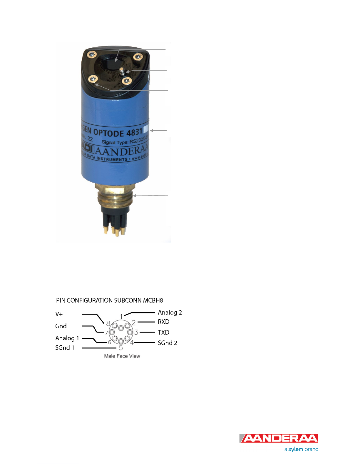
1.1 Pin Configuration ............................................................................................................11
1.2 User Accessible Sensor Properties................................................................................. 12
1.3 Specifications .................................................................................................................15
1.4 Manufacturing and Quality Control.................................................................................. 15
CHAPTER 2 Measurement Principles and Parameters ............................................................................. 16
2.1 Sensor Integrated Firmware ...........................................................................................16
2.2 Sensor Parameters.........................................................................................................17
2.3 Salinity Compensation of Data........................................................................................ 17
2.4 Depth Compensation of Data.......................................................................................... 18
CHAPTER 3 SEAGUARD®Applications.................................................................................................... 20
3.1 Installation on SEAGUARD®Platform............................................................................. 20
3.2 RedReference, Calibration Coefficients and Salinity Compensation ............................... 22
CHAPTER 4 Sensor configuration using Real-Time Collector................................................................... 25
CHAPTER 5 Connection to PC .................................................................................................................. 27
5.1 RS232 Communication Setup......................................................................................... 27
5.2 Passkey for Write Protection...........................................................................................28
5.3 Save and Reset ..............................................................................................................29
5.4 Communication Sleep..................................................................................................... 29
5.5 Available Commands for the Oxygen Optodes ............................................................... 30
5.5.1 The Get Command ..................................................................................................31
5.5.2 The Set Command................................................................................................... 31
5.5.3 Formatting the Output String.................................................................................... 32
5.5.4 XML Commands ...................................................................................................... 32
5.6 Scripting -sending a string of commands ........................................................................ 32
5.7 Sensor Configuration ......................................................................................................33
CHAPTER 6 Maintenance.......................................................................................................................... 35
6.1 Changing the Sensor Foil ...............................................................................................37
6.1.1 Procedure for Oxygen Optode 4330 and 4831......................................................... 38
6.1.2 Procedure for Oxygen Optode 4835 ........................................................................ 39
6.2 Function Test..................................................................................................................40
6.2.1 SEAGUARD®Applications....................................................................................... 40
6.2.2 Calibration Procedure using a Terminal Program..................................................... 42
Appendix 1 Theory of Operation ................................................................................................................ 45
Luminescence Decay Time ..................................................................................................46
Appendix 2 The Optical Design.................................................................................................................. 48

TD 269 OPERATING MANUAL
OXYGEN OPTODE 4330, 4831, 4835
June 2017
page 4 of 93
Appendix 3 Electronic Design .................................................................................................................... 50
Appendix 5 Mechanical Design of Optode 4835 ........................................................................................ 51
Appendix 6 Primer –Oxygen Calculations in the Sensor ........................................................................... 52
Appendix 7 Multipoint Calibration............................................................................................................... 56
Appendix 8 Illustrations .............................................................................................................................. 57
Appendix 9 Frequently Asked Questions –FAQ......................................................................................... 66
Appendix 10 List of scientific papers .......................................................................................................... 84
Appendix 11 Product Change Notification: Framework 3 .......................................................................... 86
Appendix 12 Oxygen Dynamics in Water................................................................................................... 89
Seawater and Gases ............................................................................................................ 89
Tables ..................................................................................................................................89

TD 269 OPERATING MANUAL
OXYGEN OPTODE 4330, 4831, 4835
June 2017
page 5 of 93
INTRODUCTION
Purpose and Scope
This document is intended to give the reader knowledge of how to operate, calibrate and maintain the
Aanderaa Oxygen Optodes 4330, 4835 and 4831. It also aims to give insight on how the Oxygen Optode
works.
Individually calibrated commercially available optical dissolved oxygen Optodes for ocean and fresh
water applications were introduced by Aanderaa Data Instruments in 2002. The proven long-term
stability (years) and reliability of these sensors has revolutionized oxygen measurements and several
thousand are now in use in applications ranging from streams to the deepest oceanic trenches on
earth, from fish farms to waste water, from polar ice to hydrothermal vents.
In 2002 the first MKI versions of these sensors the models 3830 and 3835 went into service.
This manual deals with the more recent MKII Optode models 4330/4835/4831. Compared to MKI the
MKII Optodes’ deliver improved electronics, optics, temperature compensation, formulas to calculate
absolute oxygen and can be individually multipoint (normally in 40 points at 5 temperatures and 8
oxygen concentrations) calibrated to an enhanced accuracy.
With the release of Framework 3 in 2011 Aanderaa introduced a new firmware version to accommodate
higher security and future expansion. Both the Smart Sensor Terminal protocol and the AADI Real Time
protocol was updated with this version of the Smart Sensor firmware, ( see appendix 11)
Aanderaa Smart Sensors utilize common communication protocols at the RS232 and RS422 interface
where the Smart Sensor Terminal protocol is a simple ASCII command string based protocol and the
AADI Real Time is an XML based protocol..Oxygen Optode 4330/4330F fits directly on the SeaGuard
top-end plate and is interfaced by means of a reliable CANbus interface (AiCaP), using XML for plug
and play capabilities. It can also be used as stand-alone sensor using RS-232 output. The sensor is
available in three different depth ratings, 300 meter, 3000 meter and 6000 meter. Oxygen Optode 4330
is also available in a fast response version called 4330F.
Oxygen Optode 4835 is the shallow water version of 4330. The sensor housing is made of Hostaform and
maximum depth rating is 300 meter. This version fits directly on the SeaGuard SW top-end plate and is
interfaced by means of a reliable CANbus interface (AiCaP), using XML for plug and play capabilities. It
can also be used as stand-alone sensor using RS-232 output.
Oxygen Optode 4831/4831F is a version build on the same platform as 4330 but with a wet mate
connector for easy integration. This sensor has analog and RS-232 output. The sensor is available in
three different depth ratings, 300 meter, 3000 meter and 6000 meter. Oxygen Optode 4831 is also
available in a fast response version called 4831F.

TD 269 OPERATING MANUAL
OXYGEN OPTODE 4330, 4831, 4835
June 2017
page 6 of 93
Document Overview
Chapter 1 is a short description of the sensors covered by this manual.
Chapter 2 is a description of measurement principles and parameters
Chapter 3 is a short description of how to use the sensor with SeaGuard.
Chapter 4 describes how to configure and use the sensor together with AADI Real-Time Collector.
Chapter 5 describes the connection to PC and the RS-232 communication protocol.
Chapter 6 describes maintenance, procedure for changing foil and functional test for the sensors.
The Appendix includes the principle behind the Oxygen Optodes, electronic and mechanical design,
calibration procedures including the Stern-Volmer Uchida formula implemented with the new Optode
framework 3 introduced in August 2012. The new firmware also allows an optional high accuracy
multipoint calibration. The appendix also include illustrations of all available cables, Frequently Asked
Questions, a list of scientific publications in which Aanderaa Optodes have played a central role and the
PCN covering the updates following introduction of framework 3.

TD 269 OPERATING MANUAL
OXYGEN OPTODE 4330, 4831, 4835
June 2017
page 7 of 93
Applicable Documents
V-9867
Assembly Drawing 4330/4330F
V-10362
Assembly Drawing 4835
V-11294
Assembly Drawing 4831
V-8700
Sensor Cable 3855, Sensor to PC, RS-232, for 4330/4835, laboratory use
V-10501
Sensor Cable 4865, Sensor to PC, RS-232, for 4330/4835, field use
V-10331
Sensor Cable 4762, Sensor to free end, for 4330/4835
V-10388
Sensor Cable 4793 for 4330/4835 remote sensor used on SeaGuard
V-11367
Sensor Cable 5280 for 4831, Sensor to IE55
DID-50042
Sensor Cable 5336 for 4831, Sensor to IE55 plus Mecca
DID-50041
Sensor Cable 5335, Sensor to PC, RS-232 for 4831
Form 712
Test & Specification Sheet, Oxygen Optode
Form 770
Calibration Certificate, O2 Sensing foil 3853
Form 710
Calibration Certificate, Oxygen Optode
D 378
Data sheet Oxygen Optode 4330/4330F
D 403
Data sheet Oxygen Optode 4831/4831F
D 385
Data sheet Oxygen Optode 4835
Abbreviations
O2
Oxygen molecule
LED Light Emitting Diode
ADC Analogue to Digital Converter
DSP Digital Signal Processor
EPROM Erasable Programmable Read Only Memory
ASCII American Standard Code for Information Interchange
MSB Most significant bit
UART Universal Asynchronous Receiver/Transmitter
RTC Real Time Clock
FAQ Frequently Asked Questions; documented in appendix of this OM
AiCaP
Automated idle line CANbus Protocol; A modified communication protocol
developed by Aanderaa
for a distributed network of smart sensors when
connected to SEAGUARD® or SMARTGUARD® loggers.
DCPS
Doppler Current Profiler Sensor is a sensor from Aanderaa to
measure ocean
currents in multiple levels, waves and tides along with other parameters. The
sensor may be used as a atand-
alone sensor or together with SeGuardII og
SmartGuard loggers
RCM Recording Current Meter is the common terminology for single point current
meters from Aanderaa.

TD 269 OPERATING MANUAL
OXYGEN OPTODE 4330, 4831, 4835
June 2017
page 8 of 93
CHAPTER 1 Short Description and Specifications
The Oxygen Optode is an optical sensor that does not consume oxygen. The measurement principle is
based on fluorescence quenching see appendix 1, while traditional polorographic oxygen sensors, often
called Clark sensors, based on electrochemical principles consume oxygen.
The optical oxygen sensors described herein belong to the Aanderaa series of smart multi-parameter
sensors.
Apart from a high quality temperature channel which is almost always included for automatic
compensation in all of Aanderaa’s series of smart sensors; Aanderaa produces other smart sensors to
measure water Currents, Conductivity, Wave/Tide and Pressure.
Features common to these sensors include:
•Internal Digital Signal Processor (DSP) to optimise data acquisition and improve accuracy,
resolution and stability
•Multi-parameter outputs measured/calculated/presented within the sensor e.g. for oxygen O2in
µM, O2in % saturation, Temperature and Raw data
•Calibration coefficients stored in sensor and unique sensor identification number
•Autonomous sampling, 1 second to 4 hour sampling interval
•AiCaP (CAN bus) communication which means that up to 20-25 sensors can be “plug and play”
connected to Aanderaa SEAGUARD®or to a SMARTGUARD® logger that automatically detects
and recognizes the sensor.
•RS232 serial communication so that these sensors can be connected directly to computers or
third party platforms e.g. data loggers from other manufacturers, gliders, floats, buoys, landers,
cable operated and autonomous vehicles,
•Optional Analog 0-5 V, 4-20 mA adaptors available for 4330 and 4835
.

TD 269 OPERATING MANUAL
OXYGEN OPTODE 4330, 4831, 4835
June 2017
page 9 of 93
Figure 1-1 Illustration of the Oxygen Optode 4330.
Figure 1-1A Oxygen Optode 4330 Pin Configuration
Screws (4) for attaching the Securing Plate
Temperature sensor
Sensing Foil
Sensor Housing
Sensor foot
O-rings

TD 269 OPERATING MANUAL
OXYGEN OPTODE 4330, 4831, 4835
June 2017
page 10 of 93
Figure 1-2A Oxygen Optode 4831 Pin Configuration
Screws (4) for attaching the Securing Plate
Temperature sensor
Sensing Foil
Sensor Housing
Wet-mate Connector
Subconn MCBH8M
Figure
1-2 Illustration of the Oxygen Optode 4831

TD 269 OPERATING MANUAL
OXYGEN OPTODE 4330, 4831, 4835
June 2017
page 11 of 93
Figure 1-3 Illustration of the Oxygen Optode 4835.
Figure 1-3A Oxygen Optode 4835 Pin Configuration
1.1 Pin Configuration
The Oxygen Optode 4330, 4831 and 4835 pin configuration is given in Figure 1-1A, 1-2A and 1-3A
above. A description of the receptacle notation is given in Table 1-1.
Screw for attaching the Securing Plate
Temperature sensor
Sensing Foil
Sensor Housing
Sensor foot
O-rings
Screw for attaching the Securing Plate
Securing Plate

TD 269 OPERATING MANUAL
OXYGEN OPTODE 4330, 4831, 4835
June 2017
page 12 of 93
Table 1-1 Description of the Pin Configuration
Signal Description
CAN_H CANbus line (dominant high)
NCG Node Communication Ground
NCR Node Communication Request
Gnd Ground
Positive supply 5-14V positive supply
NCE Node Communication Enable
BOOT_EN Boot Load Enable (do not connect)
CAN_L CANbus line (dominant low)
RS232 RXD RS232 Receive line
RS232 TXD RS232 Transmit line
Analog 1 Analog output no. 1, 0-5V
SGnd 1 Signal ground for Analog output no. 1
Analog 2 Analog output no. 2, 0-5V
SGnd 2 Signal ground for Analog output 2
1.2 User Accessible Sensor Properties
All configuration settings that determines the behavior of the sensor are called properties and are stored
in a persistent memory block (flash). One property can contain several data elements of equal type
(Boolean, character, integer etc.). The different properties also have different access levels. Table 1-2
lists all user accessible properties for Oxygen Optode 4330, 4831 and 4835.

TD 269 OPERATING MANUAL
OXYGEN OPTODE 4330, 4831, 4835
June 2017
page 13 of 93
Table 1-2 FC = Factory Configuration, UM = User Maintenance, SC = System Configuration, DS =
Deployment Setting. ENUM=Enumeration, INT =Integer, BOOL=Boolean(‘yes’/’no’)
Property Type
No of elements
Use
Category
Access Protection
RS232 applications
Product name String 31 Aanderaa Product name FC Read
Only
Product Number String 6 Aanderaa Product number
Serial Number INT 1 Serial Number
SW ID String 11 Software Identifier
SW Version INT 3 Software version (Major, Minor, Built)
HW ID X String 19 Hardware Identifier, X=1..3
HW Version X String 9 Hardware Identifier, X=1..3
System Control INT 3 For internal use
Production Date String 31 AADI Production Date, format YYYY-MM-DD
Last Service String 31 Last service date, format YYYY-MM-DD,
empty by default
Last Calibration String 31 Last calibration date, format YYYY-MM-DD
Calibration Interval INT 1 Recommended Calibration Interval in Days
Node Description String 31 User text for describing node, placement etc. UM
High
Interface ENUM 1 Sensor interface. Select either RS232 or
RS422 (N/A for Oxygen Optode)
Baudrate ENUM 1 RS232 baudrate:
300,1200,2400,4800,9600,57600,115200 1)
Flow Control ENUM 1 RS232 flow control: None or Xon/Xoff
Enable Comm
Indicator BOOL 1 Enable the Communication Sleep (‘%’) and
Communication Ready (‘!’) indicators
Comm TimeOut ENUM 1
RS232 communication activation timeout:
Always On,10 s,20 s,30 s,1 min,2 min,5 min,10
min
Salinity Float 1Salinity (PSU) for use in salinity compensation of
O2concentration
UM
High
TempCoef Float 6 Curve fitting coefficients for the temp
measurements.
PhaseCoef Float 4 Linearization coefficients for calculating
compensated phase
PTC0Coef Float 4 Raw phase temperature compensation coefficients,
normally not used (0,0,0,0)
PTC1Coef Float 4 Raw phase temperature compensation coefficients,
normally not used (1,0,0,0)

TD 269 OPERATING MANUAL
OXYGEN OPTODE 4330, 4831, 4835
June 2017
page 14 of 93
PhaseCoef Float 4 Linearization coefficients for calculating
compensated phase
FoilID String 9 Sensing Foil Identifier
FoilCoefA Float 14 Foil coefficients, general curve fit function, set A
FoilCoefB Float 14 Foil coefficients, general curve fit function, set B
FoilPolyDegT INT 28 Exponents for temperature, general curve fit
function
FoilPolyDegO INT 28 Exponents for oxygen, general curve fit function
SVUFoilCoef Float 7 Foil coefficients for the ‘Stern Volmer Uchida’
formula
ConcCoef Float 2
Linear adjustments coefficients for final O2
concentration calculation, nominal values 0 (offset)
and 1 (slope).
NomAirPress Float 1 Nominal air pressure for use in O2concentration
calculations
NomAirMix Float 1 Nominal O2percentage in air for use in O2
concentration calculations
CalDataSat Float 2 Two point calibration data, raw phase and
temperature @ 100% air saturation
CalDataAPress Float 1 Two point calibration data, air pressure (hPa)
CalDataZero Float 2 Two point calibration data, raw phase and
temperature @ 0% air saturation
Enable
RedReference BOOL 1 Controls the use of the red reference LED
RedReference
Interval INT 1
Sample interval divisor for use of red reference.
Examples: Value 1 for using red reference for each
sample. Value 10 for using red reference for each
10
th
sample.
Mode ENUM 1
Operation Mode: ‘AiCaP’, ‘Smart Sensor
Terminal’, ‘AADI Real-Time’, ‘Analog Output’
see chapter 5.7
SC Low
Enable Sleep BOOL 1 Enable sleep mode SC
Low
Enable Polled Mode BOOL 1
Enable Polled Mode (for RS232), when set to ‘no’
the sensor will sample at the interval given by the
Interval property, when set to ‘yes’ the sensor will
wait for the ‘Do Sample’ command.
Enable Text BOOL 1 Enable text, when set to ‘no’ the start up info and
the parameter text is removed
Enable
Decimalformat BOOL 1 Controls the use of decimal format in the
output string
Analog TempLimit Float 2
Lower and upper ranger limits for analog
temperature output (Output 2), default -5 to 35°C
*2)
Analog Output1 ENUM
Controls which parameter is presented at analog
Output 1; O2Concentration, AirSaturation,
CalPhase, Fixed1, Fixed2 2)

TD 269 OPERATING MANUAL
OXYGEN OPTODE 4330, 4831, 4835
June 2017
page 15 of 93
Analog Coef Float Coefficients (offset,slope) used for trimming the
analog outputs, default set to 0,12)
Enable AirSaturation BOOL 1 Controls inclusion of air saturation(%) in the output
Enable Rawdata BOOL 1 Controls inclusion of raw data in the output string
Enable Temperature BOOL 1 Controls inclusion of Temperature in the output
Enable
HumidityComp
BOOL 1
Enable compensation for vapour pressure,-disable
only for use in dry air or external humidity
compensation
Enable SVUformula BOOL 1 Refer Appendix 7
Interval Float 1 Sampling Interval in seconds DS
No
Owner String 31 Set the device owner
Location String 31 Set the location
Geographic Position String 31 Set the geographic position
Vertical Position Float 1User value for describing sensor position
1) Note! Baud rates lower than 9600 may limit the sampling frequency.
2) Applicable to 4831 only
1.3 Specifications
For product specifications refer Datasheet D378 for 4330/4330F, D385 for 4835 and D403 for
4831/4831F on our web site http://www.aaderaa.com or contact aanderaa.info@xyleminc.com
You will always find the latest versions of our documentation on the web.
Customers can register to obtain a username and password necessary to gain access to product
manuals, technical notes and software. Please contact aanderaa.info@xyleminc.com for guidance.
1.4 Manufacturing and Quality Control
Aanderaa Data Instruments products have a record for proven reliability. With over 50 years experience
producing instruments for user in demanding environments around the globe, you can count on our
reputation of delivering the most reliable products available.
We are an ISO 9001 Certified Manufacturer. As a company we are guided by three underlying principles:
quality, service, and commitment. We take these principles seriously, as they form the foundation upon
which we provide lasting value to our customers.

TD 269 OPERATING MANUAL
OXYGEN OPTODE 4330, 4831, 4835
June 2017
page 16 of 93
CHAPTER 2 Measurement Principles and Parameters
The AADI Oxygen Optode 4330, 4831 and 4835 are based on the ability of selected substances to act as
dynamic fluorescence quenchers.
The fluorescent indicator is a special platinum porphyrin complex embedded in a gas permeable foil that
is exposed to the surrounding water. Characteristic features of these foils and sensors are exceptional
sensitivity, stability and robustness. Hundreds of examples exist of field stability for periods of 1-6 years
(see summary of scientific publications appendix 11). In addition the ability to withstand high
temperatures, to have low and fully reversible pressure effects and minimal wet-dry cycling effects are
benefits of the AADI Optodes.
The 4330 and 4831 Optodes can be fitted with the standard or faster response foils. The “standard foil” is
more robust and recommended in most applications. A black optical isolation coating protects the
sensing complex from influences caused by direct incoming sunlight, exciting fluorescent particles in the
water, and biofouling. The “faster response” foils are suitable if shorter response times are required
however these foils do not have any protective optical isolation layer. Normally the foils have the same
long-term stability but the fast foils are slightly noisier. If exposed to direct sunlight they will bleach and
drift towards lower responses. It is always recommended to store sensors and spare foils in the dark and
to soak sensors in water at least 24 hours prior to calibration or deployment. Sensor are delivered with a
reusable black rubber protection cap and it is recommended to add a wet piece of natural sponge to keep
the sensor foil wet at all times during storage. For more details on these and other issue please see
pages 46 & 47 along with FAQ’s in appendix.
The sensing foil is fixed against a sapphire window by four screws and a plastic securing plate, providing
optical access to the foil by the measuring system from inside a watertight housing.
The foil is excited by modulated blue light, and the Optode measures the phase shift of a returned red
light, ref Appendix 2. By linearizing and temperature compensating, with an incorporated temperature
sensor located next to the sensing foil, the absolute O2concentration is determined.
The lifetime-based luminescence quenching principle, as used in AADI Oxygen Optodes, offers the
following advantages over electrochemical sensors:
•Not stirring sensitive (does not consume oxygen; does not require pumps)
•Direct Measurement of absolute oxygen concentrations without repeated calibrations
•Better long-term stability (stable for years)
•Less affected by pressure; Pressure behavior is predictable and fully reversible
oRepeatable
oLow Noise
oExceptionally Low Drift
The Optode can be logged directly by a PC (via the RS232 protocol) and by most PLC’s, DCP’s, I/O
devices, data loggers and systems.
2.1 Sensor Integrated Firmware
The main tasks of the sensor’s integrated firmware are to control the transmitter, sample the returned
fluorescent signal, extract the phase shift of this signal, and convert it into oxygen concentration and/or
Air Saturation value.

TD 269 OPERATING MANUAL
OXYGEN OPTODE 4330, 4831, 4835
June 2017
page 17 of 93
All the user configurable properties that can be changed for each individual sensor, i.e. calibration
coefficients, are called sensor properties. The properties can be displayed and changed using the Smart
Sensor Terminal protocol via an RS232 port, refer CHAPTER 5 for communication with the sensor using
a terminal communication program. Examples of typical terminal emulation programs are Hyper Terminal
and Tera Term
The Oxygen Optode will perform a measurement sample and present the result within the first 1.5
seconds after the Optode has been powered up.
2.2 Sensor Parameters
Engineering data are calculated by firmware in the sensor based on measured raw data and sets of
calibration coefficients stored in the sensor:
•The Oxygen content is presented in µM (1 Molar = 1 mole/litre). Conversions to other commonly used
engineering unit values are:
o1 ml/l = 44.66 µM, (real gas STP)
o1 mg/l = 31.25 µM.
Please observe that to obtain absolute concentrations of oxygen these values needs to be
salinity and pressure compensated (see below).
•The relative Air Saturation is presented in % relative to the nominal air pressure (1013.25 hPa).
These values do not need to be salinity compensated.
•The ambient Temperature is presented in ºC.
The optode raw data are the phase and amplitude of the returned signal after the luminophore quenching:
CalPhase(deg): Calibrated phase
TCPhase(deg): Temperature compensated phase
C1RPh(deg): Phase measurement with blue excitation light
C2RPh(deg): Phase measurement with red excitation light
C1Amp(mV): Amplitude measurement with blue excitation light
C2Amp(mV): Amplitude measurement with red excitation light
RawTemp(mV): Voltage from thermistor bridge.
The 4831 analog channel 1 may be set to output either; µM or %Saturation or CalPhase.
Calibration coefficients are stored in the sensors flash and are updated when recalibrated. If raw data are
not needed the user can select to turn off the delivery and logging of these.
2.3 Salinity Compensation of Data
The O2concentration sensed by the Optode is the partial pressure of dissolved oxygen in water.
Since the foil is only permeable to gas and not water, the optode cannot sense the effect of salt dissolved
in the water, hence the optode always measures as if immersed in fresh water.
If the salinity variation on site is minor (less than ±1ppt), the O2concentration can be compensated in
real-time inside the sensor by setting the internal property ‘Salinity’to the average salinity at the
measuring site.

TD 269 OPERATING MANUAL
OXYGEN OPTODE 4330, 4831, 4835
June 2017
page 18 of 93
If the salinity varies significantly, you should simultaneously measure the salinity externally and perform a
more accurate correction by a post compensation of the data. An Excel spreadsheet containing the
equations for post compensation of the measurements is available for download at the document
download site at the Aanderaa Global Library, refer www.aanderaa.com.
If the Salinity property in the sensor is set to zero, the compensated O2concentration, O2c in µM, is
calculated from the following equation:
[ ]
( )
2
0
3
3
2
210
22
SCTBTBTBBS
C
SS
S
eOO
++++
⋅=
where:
O2is the measured O2concentration
S= measured salinity in ppt or PSU
Ts= scaled temperature
+
−
=t
t
15
.273
15.298
ln
t = temperature, °C
B0=-6.24097e-3 C0= -3.11680e-7
B1=-6.93498e-3
B2=-6.90358e-3
B3=-4.29155e-3
If the Salinity property in the optode is set to other than zero (zero is the default value), the equation
becomes:
[]
( )
)()
(
2
2
2
0
2
0
3
3
2
2100 SSC
TBTB
T
BB
S
S
C
SS
S
e
OO −+++
+
−
⋅
=
Where S0 is the internal salinity setting.
2.4 Depth Compensation of Data
The response of the sensing foil decreases to some extent with the ambient water pressure (3.2% lower
response per 1000 m of water depth or dbar –investigated in detail by Uchida et al., 2008, for full
reference see publication list in appendix 11). This effect is the same for all AADI oxygen Optodes and is
totally and instantly reversible and easy to compensate for.
The depth compensated O2concentration, O2c, is calculated from the following equation:
⋅
+⋅= 1000
032
.0
1
22
d
OO
c
where:
dis depth in meters or pressure in dbar.
O2is the measured O2concentration in either µM or %.
The unit of the compensated O2concentration, O2c, depends on the unit of the O2input
NOTE! Depth compensation is not performed within the Optode.
Examples of depth compensation:

TD 269 OPERATING MANUAL
OXYGEN OPTODE 4330, 4831, 4835
June 2017
page 19 of 93
At normal atmospheric pressure (1013 mbar) the measured O2concentration should not be pressure
compensated. As the sensor is submerged you must perform pressure compensation of 0.0032% per
dbar or for every meter increase of the relative pressure.
The relative pressure = absolute pressure (measured with the optode) – atmospheric pressure (normally
set to 1013 mbar).
Example 1: The measured O2concentration with an Optode is 400 µM. The measurement was performed
at 1m depth, which is 1dbar relative pressure.
O2c= 400×1.000032= 400.012
µ
M
Example 2: The measured O2concentration with the Optode is 400 µM. The measurement was
performed at 1000m depth, which is 1000dbar relative pressure.
O2c=400×1.032= 412.8
µ
M

TD 269 OPERATING MANUAL
OXYGEN OPTODE 4330, 4831, 4835
June 2017
page 20 of 93
CHAPTER 3 SEAGUARD®Applications
The optode is equipped with a CANbus interface supporting AADI AiCaP (Automated idle line CANbus
Protocol). This standard ensures easy plug and play connection to all AADI SEAGUARD®and
SMARTGUARD®data loggers. Refer chapter 3.1 for installation of the Optode on your SEAGUARD®
Instrument.
When connected to an AiCaP bus network the Optode will report its capabilities and specifications to the
data logger at power up. The data logger assembles the information and provides the user with the
possibility to configure the instrument based on the presented nodes. This solution provides for greater
flexibility on both use and design of the different elements within the system.
Note! This chapter describes the System Configuration of the Oxygen Optode 4330and 4835. Refer
TD262a for a thorough description of configuring the SEAGUARD®Instrument, and to perform Node
Identification, Deployment settings, and Recorder settings.
Note! Metal structures submerged in water (of e.g. Stainless Steel, Aluminium, Bronze) are often
corrosion protected by sacrificial anodes. As the anode disintegrates oxygen is consumed at all “naked”
exposed metal parts with which the anode is in electrical contact. The oxygen consumption can be
significant e.g. during its lifetime, normally 1-2 years, a 130 g Zn anode mounted on a
SEAGUARD®/RDCP/RCM pressure case can consume all oxygen in about 700 l of water. In areas where
very low circulation conditions exist water parcels with lower oxygen concentrations will form and can
surround the oxygen sensors and lead to artificial dips in the oxygen readings. These effects are
detectable in environments in which oxygen is stable (e.g. less than 2 % variations over time periods of
days-weeks) and when currents are low (e.g. below 10 cm/s). In a vast majority of applications these
effects are of low/no significance. Detailed information about this can be found in the appendices.
3.1 Installation on SEAGUARD®Platform
The Oxygen Optode 4330 and 4835 can easily be installed on AADI SEAGUARD®data loggers. Power
should be turned off before connecting the sensor. We recommend that you install the Oxygen Optode in
sensor position 3, 4 or 6, refer Figure 3-1. If mounted in position 6 use patch cable to connect the optode
to the HUB card, for further installation instructions refer TD262a SEAGUARD®Platform Operating
Manual.
This manual suits for next models
2
Table of contents