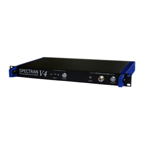
Aaronia SPECTRAN V6 User manual

Congratulations on getting your new Aaronia SPECTRAN®V6 Realtime Spectrum Analyzer. This quick start guide will
provide you with some important initial instructions for connecting it to your PC and measurement equipment. It also
shows how to install and configure the RTSA-Suite PRO PC software for performing measurements.
Check package contents
Before your new SPECTRAN®V6 can be used please verify that all necessary components are available and all
requirements are met:
USB Stick with manual, application
soware and other information
Power supply box
The SPECTRAN® V6 device itself
Power Supply (USB-C jack)
Power socket adapters
Inside the power supply box:
Below the device:
Power cable
(red, USB-C connectors on both ends)
USB cable labeled „Data”
(black, USB-A to USB-C)
USB cable labeled „Boost”
(black, USB-A to USB-C, not with RSA 250X)
Cleaning brush

Connectors
Please see the image below for a general overview of the available
connectors. Each of them will be described in more detail in the
following sections.
Use the black cable labeled “Data” to connect the “DATA” port of the
device to any USB 3.x port of your PC. USB 3.x ports are usually blue or
red and are marked with a “SuperSpeed” logo:
Connecting the SPECTRAN® V6 with the PC
Option A) Attach the proper adapter to the power supply and plug it into a power socket. Then use the red power
cable to connect the power supply with the “POWR” port on the device.
Option B) Use the red power cable and connect it to the “POWR” jack of
the device with a USB port that supports the “Power Delivery” feature.
Such ports are marked by one of the symbols shown on the right.
Power
Data
The SPECTRAN®V6 may need a second USB connection when operating at full capacity. In such scenarios connect
the black cable labeled “Boost” to the “BOOST” port of the device and a second USB 3.x port on your PC.
Do not use a USB hub for connecting the SPECTRAN®V6.
Avoid using USB 2.0 ports for connecting the SPECTRAN® V6. (While it is possible, a USB 2.0 port limits the data
rate extremely and may cause data errors and trigger error messages.)
Boost
Attention Third-party USB cables may cause problems if they do not meet the proper specifications.
In case of USB problems always make sure you are using the cables supplied by Aaronia
before contacting support.
(not for RSA 250X)
!USB 2.0
limits the
data rate
extremely
Note
In some cases, the “Data”
connection can also supply
power, and no dedicated “Power”-
connection is needed. However,
this depends on the USB port,
cable and device configuration in
the mission used, so it is recom-
mended to always supply power
using the “Power” connector.
LED status lights
(Boost /Data)
Disconnected
Connected
Datatranfer

Connecting the SPECTRAN® V6 with antennas or RF devices
The SPECTRAN®V6 provides the following connectors for antennas and/or other RF devices:
Two SMA inputs labeled Rx1 and Rx2 to
connect antennas, generators or other
measurement equipment supporting signal
strengths of up to +25 dBm (Rx2 only
supported on RSA 2000X).
One SMA output labeled Tx to connect
receiving equipment providing signal
strengths of up to +20 dBm (not suppor-
ted on RSA 250X).
RX
TX
REF
One SMB input labeled REF to connect an
external 10 MHz clock signal.
One SMB in/output labeled TRG for
synchronizing device.
One SMB in/output labeled PPM.
One SMB input labeled GPS to connect an
antenna to the integrated GPS receiver
(requires software license).
TRG
PPM
GPS
Antenna
(not included)
„Rx1“ connector
SMA cable
(not included)
„POWR“ connector
„DATA“ connector
In most scenarios, you will only connect the Rx1 input to an antenna (or other device), so your setup will look similar to this:

Installing the soware
To use the SPECTRAN®V6 RSA the Aaronia RTSA-Suite PRO analyzer software is required. A version of that is
available on the USB stick included in the package under the “\Software\Installer” folder, alternatively you can
download the most recent version at https://aaronia.com/downloads/
Installing the RTSA-Suite PRO on Windows 10 is pretty straightforward. Just double-click on the installer file on the
USB stick or in your download folder:
The installation is similar to most other Windows applications. Read each screen carefully before clicking “Next”. In
particular make sure that the “Install SPECTRAN V6 Driver” option is enabled (should be the default) on the last
page of the installation process.
Starting the soware
After the RTSA-Suite PRO is installed, start it like any other application using the start menu or desktop shortcut.
The start of the RTSA-Suite PRO may take some time during which you may not see any interface elements, please
be patient in that case, the application windows should appear within a few seconds.
Attention Linux users: The RTSA also works on Linux, but the installer is not included on the USB stick and
needs to be downloaded from our website. For obvious reasons the installer will have some differen-
ces to the Windows version, in particular it will not contain a “Install SPECTRAN V6 driver” option.
By default, the RTSA-Suite PRO will load a mission file that will connect to a connected SPECTRAN®V6 RSA, start a
measurement and display the data as spectrum, waterfall and histogram view. Of course, this only works if the
device is properly connected to the PC before starting the RTSA-Suite PRO. If all works properly, your RTSA-Suite
PRO window will look similar to this after a few seconds:
If your SPECTRAN®V6 RSA is connected as instructed, but the RTSA-Suite PRO does not display a screen similar to
the above please check for error messages in the bottom left corner of the screen and check the SPECTRAN®V6
forum at https://aaronia.com/v6-forum/ for solutions. There you will also find a lot of additional information for
using your new SPECTRAN®V6 RSA.
For more information about the RTSA-Suite PRO please visit our website at
https://aaronia.com/rtsa/ and its manual at https://aaronia.com/rtsa-manual/

RTSA interface overview
The RTSA-Suite PRO is a very complex software. Please refer to the full manual for a detailed usage guide. This
quick start guide only references a few parts of the interface that are briefly described below:
Accessing the SPECTRAN® V6 settings
The mission which is loaded by default in the RTSA-Suite PRO uses all available screen space for displaying data.
To access the settings of the SPECTRAN®V6 it is necessary to open the Spectran V6 block by clicking on the
“Spectran V6” tab above the Waterfall display in the lower part of the RTSA-Suite PRO application window. That
action will switch the lower window section from the Histogram block to the Spectran V6 block where the device
parameters can be adjusted:
SPECTRAN V6 Ribbon Bar
Access to Blockgraph Editor
Access to SPECTRAN V6 and
IQ Power Spectrum blocks CPU Saturation
Performance Monitor
The image only shows some of the available settings, it could be necessary to
scroll down and possibly open the available submenus (by clicking on the arrow
on the left side of the setting) to see them all.
In the same way the FFT parameters in the “IQ Power Spectrum” block can be
accessed, or the processing or display parameters of any other block.
Configuring the SPECTRAN® V6 RSA
The “Spectran V6” block provides many configuration options for tuning the device to your specific measurement
scenario. This quick start guide describes the most important settings briefly. If a setting is not mentioned below it
is recommended to leave it at its default value.
Group „Main“:
Device Select
device is connected the “Any available” setting is recommended.
Center Frequency Adjust this to match the frequency range to be measured.
Span Adjusts the span of the frequency range to be measured, based on the selected RTBW. “Full” yields the maxi-
mum frequency range, the other settings will reduce it by the selected factor.
Full Spectrum Makes the full RTBW spectrum available for use. By default, the outer areas are discarded to avoid possible artifacts.
Reference Level This variable controls the sensitivity of the device. Strong signals may require tuning this up to increase the
Connect / Disconnect
establish the connection automatically, but in some cases, it might be necessary to perform this connection manually.
Start / Stop Start / stop the actual measurement. The default mission should automatically start it.

Ribbon bar
Above the main display area of the RTSA-Suite PRO is the ribbon bar that allows quick access to some commonly
used parameters (same as described above). It includes a section labeled “Spectran V6”:
The controls for “Start / Stop”, “Connect / Disconnect”, “Center Frequency”, “Reference Level”, “Span”, “Frequency
Profile”, “RF Amplifier”, “Receiver Clock” and “Output Format” correspond to the settings of the same name in the
previous section, they are only duplicated here for easy access.
“Receiver Channels” is only available on RSA 2000X models and allows to select which Rx input(s) should be used
for measurement. Changing this setting will trigger a restart of the measurement which can take a few seconds as
the device has to be reinitialized.
“Receiver Select” is only available after selecting the value “Rx1/Rx2” in “Receiver Channels” and allows then to
switch between the inputs without restarting the measurement.
The “Status Display” part shows which connection is currently used and if there are any problems with it. A green
background indicates no problems, red background implies a critical error and a yellow exclamation mark is shown
when there is a non-critical issue. You can hover the mouse cursor over the element to get a tooltip with more
information on the issue.
Reference Level
Receiver Channels
Receiver Select
Output FormatReceiver Clock
Start / Stop
Connect / Disconnect
Center Frequency
RF AmplifierFrequency Profile
Status Display
Span
Attention Changing these parameters can result in an significant increase of CPU and memory consumpti-
on. Please monitor the “CPU Saturation” level in the bottom-right corner of the RTSA window.
When the bar turns red the current configuration might be too much for your hardware to handle.
Output Format
the correct output format based on the blocks connected to the block output connectors.
Spectra 1 / Spectra 2 Adjust the FFT parameters when using the “Spectra” output connectors. Spectra 2 only available on RSA 2000X.
Receiver Clock Select the bandwidth to be used. Values above 100 MHz only available on RSA 2000X or with separate band-
width option.
GPS Mode -
ble with separate GPS option.
RX Filter
that needs to be unlocked by license key. It is also possible to use the “both” setting to activate both, or “auto” to
FFT Size Mode
FFT Size Adjusts the conversion from IQ to Spectra data. Higher values will result in a smaller RBW value of the Spectra data.
FFT RBW Frequency When setting “FFT Size Mode” to “RBW” you can directly enter the desired RBW value of Spectra data here,
which will automatically adjust the FFT parameters accordingly.
Group „Board Config“:
Group „Calibration“:
When using the IQ Power Spectrum block (as done in the default mission) there are some relevant settings related
to the conversion of IQ into Spectra data:
Group „Main“:
Customizing the mission
When the default mission does not meet your requirements, you can of course change it to fit your needs. To do so
open the blockgraph editor by clicking on the pen button at the top of the application window:
That will open the blockgraph editor in a new window section:
In the blockgraph editor you can add, remove or rearrange blocks to measure and analyze data. This is done using a
drag & drop interface and connecting the in- and outputs of different blocks. Different blocks support different
datatypes indicated by the colors and labels of the connectors. Connections can only be established between
blocks supporting compatible data types (e.g. it is not possible to connect an IQ output to a Spectra input). Remo-
ving blocks is achieved by selecting the block and pressing the “Delete” key on the keyboard.
Please refer to the RTSA-Suite PRO manual at https://aaronia.com/rtsa-manual/ for details.
Mission examples
Some examples for alternative mission configurations:
One of the simplest missions possible:
The mission begins with a calibration block on the left in the blockgraph editor (see picture above). To specify which
cable, antenna and/or other RF equipment is connected to the SPECTRAN®V6, so the RTSA-Suite PRO can adjust
the data for the generated gain or loss. The Calibration block output is connected to the RF input of a SPECTRAN
V6 block to control the device. And finally, the Spectra 1 output of the SPECTRAN V6 block sends the measured data
to a ComboView block to provide a combined display of spectrum, histogram and waterfall.
This example uses the Spectra output of the SPECTRAN V6 block instead of passing the IQ data through the IQ Power
Spectrum block. It simplifies the mission configuration at the cost of less influence on the FFT parameters used.
Note
The window will
likely be opened on
the left side of the
application window
and therefore be too
small to display all
contents shown
above. F5 rearran-
ges the elements
automatically.
Note It is not possible to manually reposition elements in the blockgraph.
Drag the blocks into the editor and
connect the inputs to the fitting outputs, all by drag'n'drop.

A more complex mission to monitor a large frequency spectrum with a single SPECTRAN®V6 device, using the
Spectran V6 Sweep Zoom and Wrapped Spectrum blocks.
Download this base mission with all settings at https://v6-forum.aaronia.de/demo-mission-1/
Problems and solutions
If starting the RTSA suite PRO
does not start the measurement
automatically.
the measurement manually by clicking on the Start/Stop button in the ribbon bar should work
without problem.
Pressing the “Connect” button Check that all cables are connected correctly, and that the power supply is properly plugged into
the power socket.
The status display in the ribbon
error.
The USB connection does not provide enough bandwidth to transfer all data from the device to the
PC. There are two types of causes for this:
▷ The “DATA” connection does not support USB 3 SuperSpeed. Please make sure the port is con-
nected to a USB 3.x port on the PC or the cable does support the USB 3 “SuperSpeed” standard.
▷ The current measurement parameters are set too high. Some parameter combinations require
more bandwidth than a single USB 3 connection can handle. This can be caused by using both Rx1
and Rx2 in parallel, or using more than 122 MHz RTBW on a RSA 2000X model. When using such set-
ups please also connect the “BOOST” cable in addition to the “DATA” cable.
The Status display in the ribbon
-
-
ration. Either reduce the amount of data generated (lower Receiver Clock setting or use Spectra
example by reducing the FFT size in the IQ Power Spectrum block settings).
The device appears to be wor-
king (fan is on), but no data is
displayed.
settings. In particular using the “Spectra” connectors while using IQ “Output Format”, or using “IQ 2” or
“Spectra 2” outputs without changing the “Receiver Channels” setting.
© AARONIA AG - Subject to modifications and errors.
This manual suits for next models
1
Table of contents
Other Aaronia Measuring Instrument manuals

Aaronia
Aaronia Spectran V4 User manual

Aaronia
Aaronia Spectran V4 User manual

Aaronia
Aaronia Spectran V4 User manual

Aaronia
Aaronia SPECTRAN HF-2025E User manual

Aaronia
Aaronia NF-5030S User manual

Aaronia
Aaronia SPECTRAN V5 User manual

Aaronia
Aaronia SPECTRAN V5 User manual

Aaronia
Aaronia SPECTRAN NF User manual