Aaronia SPECTRAN V5 User manual

1.3
Aaronia AG
www.aaronia.de
Manual
SPECTRAN V5
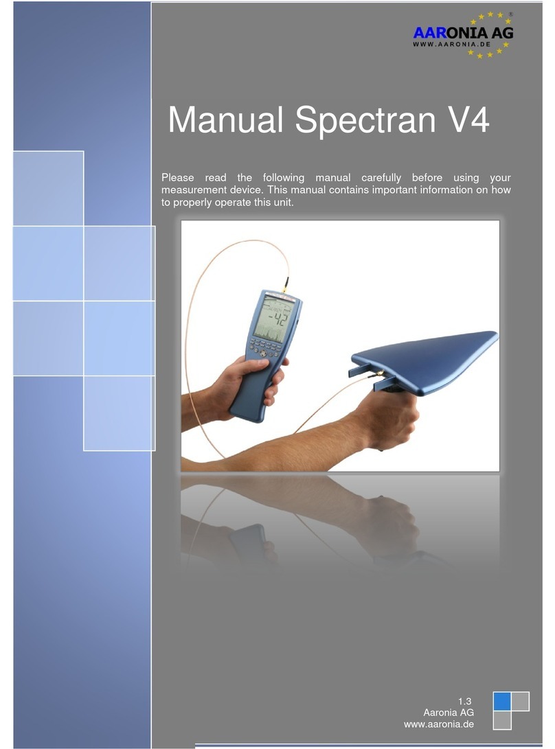
Please read the following manual carefully before using your measurement
device. This manual contains important information on how to properly
operate this unit.
®
WWW.AARONIA.DE

Manual SPECTRAN V5
© Aaronia AG 2016 | www.aaronia.com
2
TABLE OF CONTENTS
Table of Contents
1. INTRODUCTION ................................................................................................. 5
1.1. Liability.....................................................................................................................................5
1.2. Warranty...................................................................................................................................5
1.3. Safety Guidelines...................................................................................................................6
1.4. Scope of delivery...................................................................................................................7
2. CONNECTORS ................................................................................................... 8
2.1. Power Cable / Battery Charging .......................................................................................8
2.2. USB Ports (Master & Slave) ................................................................................................9
2.3. Audio Port................................................................................................................................9
2.4. µSD Card (internal storage) ..............................................................................................10
2.5. Aaronia UHSC.......................................................................................................................10
2.6. SMA Ports (50 Ohm)............................................................................................................11
2.7. Powering the device with an external power supply..................................................12
3. OVERVIEW FRONT PANEL............................................................................... 13
3.1. Control Elements.................................................................................................................13
3.2. Docking Station....................................................................................................................15
4. FUNCTIONS ..................................................................................................... 16
4.1. Main Menu .............................................................................................................................16
4.2. Menu Items............................................................................................................................17
4.2.1. Center (middle frequency).........................................................................................17
4.2.2. Span (frequency range)..............................................................................................18
4.2.3. Start Frequency & Stop Frequency .........................................................................19
4.2.4. Bandwith (Bandwidth) ................................................................................................20
4.2.5. SweepTime ....................................................................................................................20
4.2.6. RefLevel (reference level) ..........................................................................................21
4.2.7. Ampt Range (dynamics).............................................................................................21

Manual SPECTRAN V5
© Aaronia AG 2016 | www.aaronia.com
3
TABLE OF CONTENTS
4.2.8. Attenuator ......................................................................................................................22
4.2.9. Preamplier ...................................................................................................................22
4.2.10. Demod (demodulator / audio analysis) ..................................................................23
4.2.10.1. Demod BW .....................................................................................................................24
4.2.11.1. Marker (Cursor) ............................................................................................................24
4.2.12. Load & Save ..................................................................................................................25
4.2.13. Limits ..............................................................................................................................25
4.2.14. JTFA (Optimize the symbol processing)................................................................25
4.2.15. Display Mode.................................................................................................................26
4.2.16. DTS Display Mode........................................................................................................27
4.2.17. DTS Histogram View ...................................................................................................27
4.2.18. DTS Waterfall Display .................................................................................................28
4.2.19. SOFT Mode ....................................................................................................................29
5. CORRECT MEASUREMENT.............................................................................. 30
5.1. Noiseoor .............................................................................................................................30
5.2. Harmonics .............................................................................................................................31
5.3. Sensitivity..............................................................................................................................31
5.4. Measurement inaccuracy ..................................................................................................32
5.5. Measurements of satellite TV ...........................................................................................33
5.6. Measurements with a direct cable connection ............................................................33
6. SPECTRUM ANALYSIS BASICS........................................................................ 34
6.1. What is a frequency range? ..............................................................................................34
6.2. Differences between exposure limits .............................................................................34
6.3. Applications of spectrum analysis..................................................................................34
7. PHYSICAL UNITS ............................................................................................. 36
7.1. Measuringtransmissionpower(dBm;dBμV) ..............................................................36
7.2. Field strength [V/m; A/m] and power density [W/m²]..................................................36
7.3. Calculating the wavelength in [m]...................................................................................37
7.4. Calculating the „close-up range“ in [m] ........................................................................37
7.5. Calculating power density [W/m²] from power [dBm] ................................................38
Manual SPECTRAN V5
© Aaronia AG 2016 | www.aaronia.com
4
TABLE OF CONTENTS
8. TABLES............................................................................................................ 39
8.1. Convesion tables.................................................................................................................39
Table 1: Conversion dBm to W/m² with HyperLOG-antenna.......................................39
Table2:ConversionfromW/m²toμW/cm²andmW/cm² ............................................40
Table3:ConversionfromμW/cm²toV/mandA/m ......................................................40
Table 4: dBm to dBW and W ..........................................................................................41
Table 5: Frequency, wavelength and frequency band denomination ........................41
Table6:PoweramplicationfactorandcorrespondingvalueindB .........................41
8.2. Frequency tables .................................................................................................................42
Table 7: Cell phone frequencies and providers ...........................................................42
Table 8: German GSM900 frequencies and providers.................................................42
Table 9: German GSM1800 frequencies and providers...............................................43
Table 10: German UMTS frequencies and providers...................................................44
9. INDEX............................................................................................................... 45

Manual SPECTRAN V5
© Aaronia AG 2016 | www.aaronia.com
5
INTRODUCTION
1. Introduction
Dear customer,
By purchasing this Spectran high-frequency measurement device you acquired a professional
piece of equipment which allows measurement of high-frequency elds.
The measuring instrument has been constructed according to state-of-the-art technology and
fullls the requirements of the applicable European and national guidelines.
Please note: For measurement of low frequency elds (high-voltage lines, traction power, var-
ious household appliances etc.) you need additional one of the NF series Spectran models.
1.1. Liability
This document was compiled with great care and checked for accuracy.
Nevertheless mistakes cannot be excluded. We do not take over any liability. We cannot guar-
antee the completeness, the correctness and the accuracy of information.
We reserve ourselves the right to change our products, specications and documentations
without any notice. We have no obligation for revision of documents and manuals we delivered
in the past.
1.2. Warranty
Despite the greatest care in development and production of this device and the free software
RTSA Suite; Aaronia AG only takes liabilities for certain purposes, if this has been assured in
writing. No warranty can be assumed for the performance and awlessness of the software for
all usage conditions and cases and for the results produced when utilized by the user. No ad-
ditional guarantees or assurances are made regarding marketability, freedom of defect of title,
integration or usability for certain purposes unless they are required in accordance with the law
and cannot be limited. Justied guarantee claims are limited to the right of require rectication
or replacement delivery. Regarding infringements, violations of patents, rights of ownership or
the freedom from interference by third parties, Aaronia AG cannot warrant or guarantee that it
is free of error.

Manual SPECTRAN V5
© Aaronia AG 2016 | www.aaronia.com
6
INTRODUCTION
1.3. Safety Guidelines
In the event of any damages resulting from failure to follow these operating instructions, the
claim under guarantee is discharged. We accept no liability for consequential damages.
In the event of property and personal damages resulting from improper handling or failure to
follow safety advices, we accept no liability.
For reasons of safety and admissibility (CE) the unauthorized conversion and/or alteration of
the product is not permitted.
As voltage source, please only use a property mains socket (100-240Volt, 50/60Hz). Make
sure that the cable isn’t squeezed or damage by sharp edges.
In order to avoid any damage, please read this user manual carefully before starting to use the
device.
The commissioning should only be performed by qualied and instructed personnel.
Never expose the device to water. Never use it outdoors while it is raining. Otherwise the sen-
sitive electronics could be damaged.
Avoid to high temperatures. Do not leave the device on a heating, in direct sunlight or in your
car.
The device is maintenance-free. Only clean it externally with a damp cloth.
Due to the high sensitivity, the sensors and display of this device are sensitive to shock; hence
it should be handled with care. For safekeeping and transport, please use the included case.
Even though the device is well secured through the use of counter-sunk screws, it should still
not be reachable by children as it could easily be diverted from its intended use.
This device is connected to a mains socket and the derived voltages, it is not meant for the
hands of children.
Consider the regulations for prevention of industrial accidents for electrical installations and
equipment, by government safety organization in industrial facilities.
In schools, educational establishments, hobby and self-help workshops the operation of this
product must be supervised by trained personnel.

Manual SPECTRAN V5
© Aaronia AG 2016 | www.aaronia.com
7
INTRODUCTION
1.4. Scope of Delivery
Included in the Delivery:
a) SPECTRAN V5 Analyzer
b) OmniLOG 70600 (700MHz-6GHz) antenna
c) USB stick with USB driver, PC software and manual
d) Charger (power supply) with four international power adapters
e) Aaronia 8000mAh NiMh battery (not visible, because built into SPECTRAN)
f) Outdoor transport case
g) Docking Station (optional)
Please check immediately after receiving the package for completeness. Report missing parts
immediately to Aaronia or your local Aaronia dealer.

Manual SPECTRAN V5
© Aaronia AG 2016 | www.aaronia.com
8
CONNECTORS
WARNING:
Avoid overloading the input by feeding too much power, otherwise the highly
sensitive electronics may be destroyed!
The maximum permitted peak power that can be applied at the input of the
SPECTRAN V5 is:
-ActivatedPreamplier:Max.0dBm(Peak)
-DeactivatedPreamplier:Max.+20dBm(Peak)
2. Connectors
2.1. Power Cable / Battery Charging
Standardized 3.5mm mono „jack“. The input
voltage must be between 5V and 5.9V DC (di-
rect current). The included power supply pro-
vides a voltage of 5.5V at up to 6A (33W).
While being operated, the analyzer needs about
23W, without internal battery only 18W. To oper-
ate the device connect the charger to a power
supply, connect the jack plug of the charger with
the power connector of the SPECTRAN. The
charging LED of the SPECTRAN should turn
red.
Now the internal battery is being charged au-
tomatically. A complete charge cycle takes ap-
proximately 8-10 hours. When the battery is fully
charged, the charging LED turns green (power
supply has to be connected).

Manual SPECTRAN V5
© Aaronia AG 2016 | www.aaronia.com
9
CONNECTORS
2.2. USB Ports (Master & Slave)
2 Mini-USB „B“ ports (5-pins)
2.3. Audio Port
Standardized 3,5 mm mono jack-plug
USB MASTER
For the direct communication with a computer
or notebook, for example for reading out the
data logger, loading rmware updates or using
the SPECTRAN PC software „RTSA Suite“. The
„RTSA Suite“ enables a real-time connection to
the analyzer and a highly advanced signal anal-
ysis at the PC.
USB SLAVE (currently disabled)
For connecting additional hardware, for exam-
ple our GPS Logger, IsoLOG 3D Mobile antenna
etc.
TIP: In order to connect the device to a PC, we
recommend the specially shielded Aaronia USB
2.0 cable (USB A to mini USB B 5-pin), which
has EMC ltering (see Aaronia accessories).
You can connect a headset with a standardized
2.5 mm mono „jack“ to the audio port.
You can also connect the audio port with an
adapter cable to the audio input (Phono, CD,
Line in, Mic, etc.) of your PC

Manual SPECTRAN V5
© Aaronia AG 2016 | www.aaronia.com
10
CONNECTORS
2.4 µSD Card (internal removable storage)
2.5. Aaronia UHSC
With our special μSD cards, you can record up
to 64GBs or 128GBs of measurement data in-
side the analyzer. The μSD card works under
FAT32 and can thus be directly read on a PC via
the included adapter.
64GB is sufcient for approx. 30 min of mea-
surement data (with full data throughput).
The μSD card is currently not supported, but can
be activated by a rmware update.
The Aaronia UHSC port allows direct access to
the SERDES outputs / inputs of the ECP3 FPGA
SPECTRAN V5. These provide extremely fast
data transfer of up to 4x3GSPS.
Corresponding adapters for USB 3.0, USB 3.1
and Gigabit Ethernet respectively are being pre-
pared.

Manual SPECTRAN V5
© Aaronia AG 2016 | www.aaronia.com
11
CONNECTORS
2.6. SMA Ports (50 Ohm)
The SPECTRAN V5 has 3 SMA ports, which are assigned as follows:
Vector generator (output) / OPTION. Can be activated via software key
RF (input)
Power meter (input) / OPTION. Can be activated via software key starting from RF 80100
The optional vector generator output allows the playback of IQ signals in the frequency range
from 45MHz to 6GHz with up to 15dBm of output power, which were previously recorded via
USB or on the internal μSD card. This option can be enabled through the rmware (currently
inactive).
The RF input is the actual connection of the SPECTRAN V5 to the outside world. The included
antenna can be connected here.
The optional power meter input allows the measurement of ultra short signals in the frequency
range up to 40GHz. This option can be enabled through the rmware (currently inactive).

Manual SPECTRAN V5
© Aaronia AG 2016 | www.aaronia.com
12
CONNECTORS
2.7. Powering the device with an external power supply
In addition to charging the internal battery, the included power supply also allows to operate the
analyzer independently of the internal battery pack.
Other DC sources between 5V and up to a maximum of 5.9V can also be connected. A 3.5mm
jack plug must be used as the connecting plug. The connection plug has to be poled as the
following:
Internal pole „plus“ / external pole „minus“
An optional power adapter for a 12V connection available from Aaronia makes it possible to
operate the analyzer in the car.
Please note that by operating the analyzer with the power supply, additional interferences
are produced by the power supply, that might distort the measurement result. To avoid these
possibly occurring interferences for long-term measurements, we recommend to operate the
analyzer via a large, external battery. Those can (on average) provide power up to several
weeks. The power or battery packs from specialized electronics retailers are particularly ad-
vantageous. These usually have a regular 12 V connection and can therefore be operated with
the afore mentioned adapter cable.
CAUTION: All cables / devices that you connect to the external power
connector of the SPECTRAN V5 must provide a direct current of 5V up to
5.9V. A standard plug with a 3.5 mm diameter must be used as the plug (In-
ternal polarity PLUS - external polarity MINUS)
Pay attention to the cable cross-section, because without an internal battery
the device requires around 18W of power. With an internal battery around
23W of power are needed because of the additional charging circuit

Manual SPECTRAN V5
© Aaronia AG 2016 | www.aaronia.com
13
FRONT PANEL
3. OVERVIEW FRONT PANEL
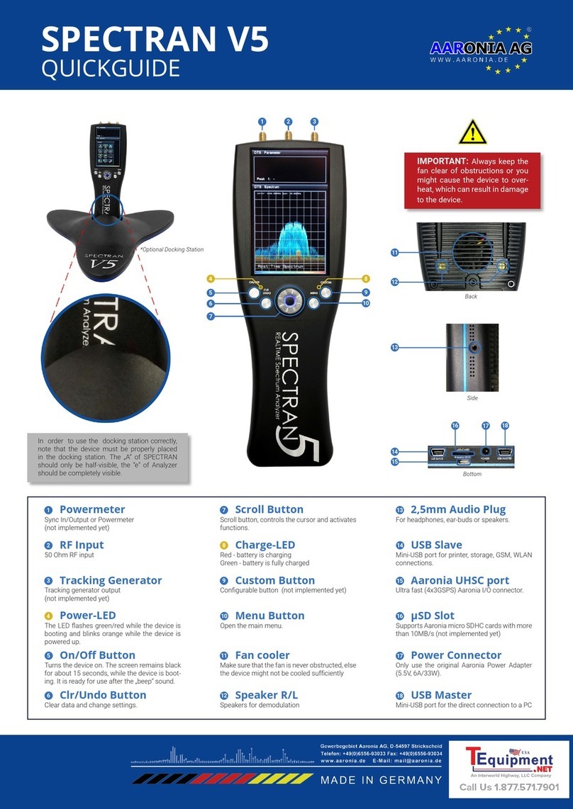
3.1. Control elements

Manual SPECTRAN V5
© Aaronia AG 2016 | www.aaronia.com
14
FRONT PANEL
On/Off-Button
On/Off LED
Turns the device (Booting takes about 10 seconds) on or
off.
Emergency shutdown (e.g. during a crash): Hold the but-
ton for about 10 seconds until the device is turned off. The
related LED „ickers“ orange while the device is booting.
After the device has been successfully booted, the LED
takes over the control function: During normal operation,
the LED ashes orange in a one second rhythm. When the
device crashes, the LED lights permanently .
Clear-/Undo-Button Currently not assigned
Rotary knob In „Demodulation“ mode:
Move the displayed demodulation marker in the spectrum
(turn the rotary knob to the right or left)
In „Marker“ mode:
Move the displayed marker in the spectrum (turn the rota-
ry knob to the right or left)
Menu Button Opens the main menu. The following operation is done by
touch screen. Please use the included touch pens which
are attached to the back of the SPECTRAN V5. You can
also operate the menu with your nger, but the precision
will be much lower.
Custom-Button
Custom LED
In „Waterfall“ mode:
Adjust the color table automatically.
The LED will light RED when the external power supply is
connected (battery charging). It might take up to 30 sec-
onds to detect the external power supply.
The LED lights GREEN when the internal battery is
charged AND the external power supply is connected.
ATTENTION: Please check, particularly in regard to the
docking station, that the charge LED lights up - otherwise
you have not inserted the device properly into the docking
station and the battery cannot be charged. A USB connec-
tion to the device might also not be possible.

Manual SPECTRAN V5
© Aaronia AG 2016 | www.aaronia.com
15
FRONT PANEL
3.2. Docking Station
The docking station allows a more convenient operation with the SPECTRAN V5, especially
if the device is connected via USB to a computer/notebook/tablet. Furthermore it ensures a
perfect heat dissipation, because the fan can operate unobstructed - therefore we recommend
to use the docking station whenever possible.
Connect the long, blue power cord of the docking station
to the included 5.5V adapter of the SPECTRAN V5 and
connect the adapter to your power supply. Now connect
the long, blue MASTER-USB cable of the docking station
to your PC (if available /desired) - ready.
Currently the short, blue SLAVE USB cable of the docking
station is not activated and therefore does not have to be
connected.
Once you have inserted the device into the docking station, the CUSTOM LED of the V5 should
light up RED. This means that the battery is charging. It may take up to 60 seconds to detect
the external power supply. The CUSTOM LED lights up GREEN when the internal battery is
charged AND the external power supply is connected.
CAUTION: For the docking station please make sure that the charging LED of the
V5 lights up, otherwise you have not properly inserted the device into the docking
station and the battery cannot be charged. In this case a USB connection to the
device might also not be possible.
The gure below shows the proper position: More than half of the capital „A“ of „SPECTRAN“
must be covered and only the small „e“ of „Analyzer“ is fully visible.

Manual SPECTRAN V5
© Aaronia AG 2016 | www.aaronia.com
16
FUNCTIONS
NEVER force the device into the docking station. A little bit of pressure and some slight back
and forth movements might be needed until the device is fully locked into place, as shown
above. Please make sure that the device is placed correctly into the docking station!
4. Functions
4.1. Main menu
Tap the touch screen to open the main menu. You
can operate the whole analyzer with the menu
control:
Press the „Return“ button to leave the menus
or to cancel a selection/input.
Press the „Delete“ button to delete an input.
Some menus like „CenterFrq have no „Re-
turn“ button. In this case you can only exit the
menu by entering a respective number value.
Changes are always adopted directly when leav-
ing the menu and you will return directly to the
spectrum display, sub menus are skipped.

Manual SPECTRAN V5
© Aaronia AG 2016 | www.aaronia.com
17
FUNCTIONS
Tip: In the spectrum display the following informations are displayed constantly,
from the left to the right:
Center frequency and SPAN
This provides a quick overview during ongoing measurements.
4.2. Menu Items
There are two options to set the frequency range manually:
- via CenterFrq (center frequency) and Span (frequency width) or
- via StartFrq & StopFrq (Start- and-Stop frequency)
4.2.1. Center (middle frequency) Default: 940MHz
Displays the frequency in the middle of the screen. In case
of changes to the middle frequency, the span parameter will
be adopted. Advantage: Quick check of different frequency
ranges with identical span and without changes to the start-/
stop frequencies.

Manual SPECTRAN V5
© Aaronia AG 2016 | www.aaronia.com
18
FUNCTIONS
4.2.2. Span (frequency range) Default: 44MHz
Span determines the frequency range for the measurement.
The afore mentioned center frequency is not affected. In-
stead in case of changes to the span, the „Start/Stop-fre-
quency“ will automatically be adjusted to retain the Span.
The Span function is comparable with a „magnier function“,
which, however, only works on the X axis.
In real time mode the Span cannot be chosen freely. In-
steadthefollowingxedREALTIMEbandwidthscanbe
chosenduetotheinternalltermatrix:
175MHz (Optional)
88MHz (Optional)
44MHz
22MHz
11MHz
5,5MHz
2,7MHz
1,09MHz
547kHz
219kHz
109kHz
54,7kHz
21,9kHz
10,9kHz
5,47kHz
2,19kHz
If you enter a „wrong“ Span, the next closest Span will
be chosen automatically. For example if you enter 40MHz
Span, 44MHz will be chosen automatically.
Example: Enter middle frequency „2450“ MHz, then:
Enter 40MHz Span measuring range = 2.440MHz to 2.460MHz
Enter 200kHz Span measuring range = 2.439,9MHz to 2.440,1MHz
An enlargement / reduction of the resolution is always „centered“ around the middle frequency.
The grid display allows for a rapid frequency allocation of the individual signal sources, since a
box always corresponds to 1/10 of the set span.

Manual SPECTRAN V5
© Aaronia AG 2016 | www.aaronia.com
19
FUNCTIONS
In SOFT mode the Span can be freely selected and may be very large. Please note however,
that currently the RBW is still xed at 200kHz. Because of the screen size, we recommend that
the span in this mode should be no more than 1GHz and no less than 5MHz.
4.2.3. StartFrq & StopFrq (Start- & Stop-frequency)
StartFrq (Start frequency) determines at which frequen-
cy the measuring range should start, while StopFrq (Stop
frequency), determines at which frequency the measuring
range should stop. This results in the entire frequency range
(Span), which is measured.
The displayed grid allows for a rapid frequency allocation
of the individual signal sources, since a box always corre-
sponds to 1/10 of the set span
Tip: A large frequency range reduces the measurement accuracy and makes
the presentation on the X-axis more difcult. Therefore single signals, especially
those close to each other, are often indistinguishable. For a better presentation of
large-frequency ranges, we strongly recommend to use the supplied RTSA Suite
software.
Reduce the frequency range, so you can explore the range in more detail. You get
a much higher level of detail and a higher measurement accuracy. Therefore we
only recommend a large frequency range to get a quick overview, but not for an
accurate measurement.

Manual SPECTRAN V5
© Aaronia AG 2016 | www.aaronia.com
20
FUNCTIONS
4.2.4. Bandwith (Bandwidth) Default: 200kHz (only SOFT mode)
Bandwith (Bandwidth) simultaneously sets the level of detail
and sensitivity. In real time mode this function cannot be
set manually, instead the bandwidth is calculated auto-
matically from the Span. The formula here is Span/220 =
Bandwidth. So for a Span of 44MHz the bandwidth cor-
responds to 200kHz.
For a high bandwidth the measurement is fast, but the dis-
play is relatively inaccurate and the sensitivity is relatively
low. Weak signals can no longer be recorded.
The smaller the bandwidth, the longer the measurement, but
the more accurate the display and weaker signals can be
displayed. For example, a signal, previously measured with
a high bandwidth, might turn out to be multiple, narrow band
signals lying closely together when measured with a lower
bandwidth.
The bandwidth can still not be selected in SOFT mode.
4.2.5. SweepTime (Sweep time) Default: 10mS (only in SOFT mode)
Determines the measurement period. The higher the sweep
time the more accurate the measurement, but the longer the
measurement period.
This item is disabled in real time mode, because that
mode always measures with the maximum sweep time.
Please note: A faster sweep time, depending on SPAN and
RBW, is not always implemented since the hardware may
not. Therefore the sweep time should be no less than 5 mS.
Other manuals for SPECTRAN V5
1
Table of contents
Other Aaronia Measuring Instrument manuals

Aaronia
Aaronia Spectran V4 User manual

Aaronia
Aaronia Spectran V4 User manual

Aaronia
Aaronia SPECTRAN HF-2025E User manual

Aaronia
Aaronia SPECTRAN V6 User manual

Aaronia
Aaronia Spectran V4 User manual

Aaronia
Aaronia SPECTRAN NF User manual

Aaronia
Aaronia SPECTRAN V5 User manual

Aaronia
Aaronia NF-5030S User manual