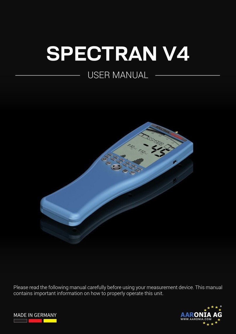
Aaronia Spectran V4 User manual

Manual Spectran V4
Please read the following manual carefully before using your
measurement device. This manual contains important information on how
to properly operate this unit.
1.3
Aaronia AG
www.aaronia.de

HW V4 / © 2005 – 2013 Aaronia AG, DE-54597 Strickscheid
2
Manual Spectran V4 Introduction
Inhaltsverzeichnis
1.
INTRODUCTION .............................................................................................. 6
1.1.
Liability ...................................................................................................................................... 6
1.2.
Warranty .................................................................................................................................... 6
1.3.
Safety Guidelines...................................................................................................................... 7
1.4.
Scope of delivery ...................................................................................................................... 8
2.
CONNECTIONS ............................................................................................. 10
2.1.
Jog Dial / volume control ....................................................................................................... 10
2.2.
USB Connector ....................................................................................................................... 10
2.3.
Audio Output ........................................................................................................................... 11
3.
POWER CONNECTION ................................................................................. 11
3.1.
External DC input (battery charger / mains operation)....................................................... 11
3.2.
Operating with an external power supply ............................................................................ 12
4.
OVERVIEW FRONT PANEL .......................................................................... 13
4.1.
Operating Equipment ............................................................................................................. 13
4.2.
Numeric block (hotkeys) ........................................................................................................ 14
4.3.
LC Display ............................................................................................................................... 15
4.4.
The display shows.................................................................................................................. 16
5.
FUNCTIONAL DESCRIPTION ....................................................................... 17
5.1.
Technical data ......................................................................................................................... 17
5.2.
Main menu ............................................................................................................................... 18
5.3.
Menu items .............................................................................................................................. 19
5.3.1.
Center (center frequency) .............................................................................................. 19
5.3.2.
Span (frequency range width) ....................................................................................... 19
5.3.3.
fLow & fHigh (start & stop frequency) ............................................................................. 20
5.3.4.
RBW (bandwidth).............................................................................................................. 21
5.3.5.
VBW (video filter) .............................................................................................................. 21
5.3.6.
SwTime (sweep-time)....................................................................................................... 22
5.3.7.
Reflev (referenz-level) ...................................................................................................... 22
5.3.8.
Range (dynamics)............................................................................................................. 23
5.3.9.
Atten (attenuator) ............................................................................................................. 24
5.3.10.
PreAmp (internal pre-amplifier / option 020).................................................................... 24
5.3.11.
Demod (Demodulator /audio-analysis/GSM-Decoder)..................................................... 25

HW V4 / © 2005 – 2013 Aaronia AG, DE-54597 Strickscheid
3
Manual Spectran V4 Introduction
5.3.11.1.
Demod (GSM-Decoder) ................................................................................................... 26
5.3.12.
AudInd (Audio-Indicator / “bug tracer” – option 015) ...................................................... 26
5.3.13.
Detect (Detector type) ...................................................................................................... 27
5.3.14.
Disp (display mode).......................................................................................................... 28
5.3.15.
Unit (set unit) .................................................................................................................... 29
5.3.16.
MrkCnt (set number of markers) ...................................................................................... 30
5.3.17.
MarkLvl (set starting level for markers)............................................................................ 30
5.3.18.
MrkDis (marker display mode) ......................................................................................... 31
5.3.19.
BackBB (change bargraph display mode, option 20x).................................................... 32
5.3.20.
AntTyp (configure connected antenna)........................................................................... 32
5.3.21.
Cable (configure antenna connection cable / attenuator) ................................................ 33
5.3.22.
RefOff (Set Offset or UBBV-Preamplifier) ........................................................................ 33
5.3.23.
GSMbst (select GSM Burst-Type).................................................................................... 34
5.3.24.
GSMdst (GSM Slot-Distance) .......................................................................................... 34
5.3.25.
Calib ( in preparation, currently not usable) ..................................................................... 34
5.3.26.
Bright (Set display brightness)......................................................................................... 34
5.3.27.
Logger (start recording/Data Logger)............................................................................... 35
5.3.28.
Setup (organize programs)............................................................................................... 38
6.
FIRST OPERATIONAL STEPS...................................................................... 40
6.1.
One-hand operation................................................................................................................ 41
6.2.
OmniLOG 90200 ...................................................................................................................... 42
6.3.
Pistolengriff ............................................................................................................................. 42
6.4.
Hardware-Setup ...................................................................................................................... 43
7.
CORRECT MEASUREMENT ......................................................................... 45
7.1.
Noise floor ............................................................................................................................... 45
7.2.
Harmonics ............................................................................................................................... 46
7.3.
Measurement of wireless LAN & cellphones ....................................................................... 46
7.4.
Attenuator-mode „Auto“ ........................................................................................................ 47
7.5.
Sensitivity ................................................................................................................................ 47
7.6.
Measurement inaccuracy....................................................................................................... 48
7.7.
The cursor and zoom features .............................................................................................. 49
8.
FIRST MEASUREMENT ................................................................................ 50
8.1.
Prepair device ......................................................................................................................... 50
8.2.
Basics ...................................................................................................................................... 50
8.3.
Measurement........................................................................................................................... 50
8.4.
Operation mode „Spectrum analysis“.................................................................................. 50
8.5.
Hold-function .......................................................................................................................... 51
8.6.
The „panning approach“........................................................................................................ 52
HW V4 / © 2005 – 2013 Aaronia AG, DE-54597 Strickscheid
4
Manual Spectran V4 Introduction
8.7.
Operation mode “Exposure limit calculation”..................................................................... 52
8.8.
Operation mode Audio-output (demodulation) ................................................................. 54
8.9.
Operation mode broadband detector (Peak power meter)................................................. 57
8.10.
Manual setting of a frequency range .................................................................................... 59
9.
TIPS AND TRICKS......................................................................................... 61
9.1.
Quick Zero-span sweep (Time Domain Mode)..................................................................... 61
9.2.
„Turbo“Sweep for small frequency ranges ......................................................................... 61
9.3.
„Turbo“Sweep for larger frequency ranges......................................................................... 62
9.4.
Allocating keys with your own measurement settings....................................................... 62
9.5.
Dect analysis ........................................................................................................................... 62
9.6.
Exposure limit calculation (display in W/m² with „Weak“ signals .................................... 63
9.7.
Conversion of measurement results to other units ............................................................ 63
9.8.
Correct settings for manual input/measurement ................................................................ 63
9.9.
Measurement of satellite TV .................................................................................................. 64
9.10.
Measurement with a direct cable connection ...................................................................... 64
10.
SPECTRUM ANALYSIS BASICS .................................................................. 65
10.1.
What is a frequency range?................................................................................................... 65
10.2.
Big difference between exposure limits............................................................................... 65
10.3.
Application of spectrum analysis ......................................................................................... 66
11.
PHYSICAL UNITS.......................................................................................... 70
11.1.
Measuring transmission power (dBm; dBµV)..................................................................... 70
11.2.
Field strength [V/m; A/m] and power density [W/m²].......................................................... 70
11.3.
Interesting facts regarding high-frequency formula ........................................................... 71
11.4.
Calculating the wavelength in [m] ....................................................................................... 72
11.5.
Calculating the „close-up range“ in [m]............................................................................... 73
11.6.
Calculating power density [W/m²] from power [dBm]......................................................... 73
12.
TABLES AND EXPOSURE LIMITS ............................................................... 74
12.1.
Convesion tables .................................................................................................................... 74
Table 1: Conversion dBm to W/m² with HyperLOG-antenna ............................................................ 74
Table 2: Conversion from W/m² to µW/cm² and mW/cm² ................................................................. 76
Table 3: Conversion from µW/cm² to V/m and A/m........................................................................... 76

HW V4 / © 2005 – 2013 Aaronia AG, DE-54597 Strickscheid
5
Manual Spectran V4 Introduction
Table 4: dBm to dBW and W ............................................................................................................. 76
Table 5: Frequency, wavelength and frequency band denomination................................................ 77
Table 6: Power amplification factor and corresponding value in dB: ................................................ 77
12.2.
Frequency tables .................................................................................................................... 78
Table 7: Cell phone frequencies and providers................................................................................ 78
Table 8: German GSM900 frequencies and providers...................................................................... 78
Table 9: German GSM1800 frequencies and providers.................................................................... 79
Table 10: German UMTS frequencies and providers........................................................................ 80
12.3.
Exposure limits ....................................................................................................................... 81
12.4.
Device exposure limits........................................................................................................... 83

HW V4 / © 2005 – 2013 Aaronia AG, DE-54597 Strickscheid
6
Manual Spectran V4 Introduction
1. Introduction
Dear customer,
By purchasing this Spectran high-frequency measurement device you acquired a
professional piece of equipment which allows measurement of high-frequency fields.
The measuring instrument has been constructed according to the current state of the art and
fulfills the requirements of the applicable European and national guidelines.
Please note: For measurement of low frequency fields (high-voltage lines, traction power,
various household appliances etc.) you need additional one of the NF series Spectran
models.
1.1. Liability
This document was compiled with great care and checked for accuracy.
But nevertheless mistakes cannot be excluded. We do not take over any liability. We cannot
guarantee the completeness, the correctness and the accuracy of information.
We reserve ourselves the right to change our products, specifications and documentations
without any notice. We have no obligation for revision of documents and manuals we
delivered in the past.
1.2. Warranty
Despite the greatest care in development and production of this device and the software
MCS for free; Aaronia AG takes only liabilities for certain purposes, if this has been assured
in writing. No warranty can be assumed for the performance and flawlessness of the
software for all usage conditions and cases and for the results produced when utilized by the
user. No additional guarantees or assurances are made regarding marketability, freedom of
defect of title, integration or usability for certain purposes unless they are required in
accordance with the law and cannot be limited. Justified guarantee claims are limited to the
right of require rectification or replacement delivery. Regarding infringements, violations of
patents, rights of ownership or the freedom from interference by third parties, Aaronia AG
cannot warrant or guarantee that it is free of error.

HW V4 / © 2005 – 2013 Aaronia AG, DE-54597 Strickscheid
7
Manual Spectran V4 Introduction
1.3. Safety Guidelines
In the event of any damages resulting from failure to follow these operating instructions the
claim under guarantee is discharged. We accept no liability for consequential damages.
In the event of property and personal damages resulting from improper handling or failure to
follow safety advice, we accept no liability.
For reasons of safety and admissibility (CE) the unauthorized conversion and/or alteration of
the product is not permitted.
As voltage source please only use a property mains socket (100-240Volt, 50/60Hz). Make
sure that the cable isn’t squeezed or damage by sharp edges.
In order to avoid any damage, please read this user manual carefully before starting to use
the device.
The commissioning should only be performed by qualified and instructed personnel.
Never expose the device to water. Never use it outdoors while it is raining. Otherwise the
sensitive electronics could be damaged.
Avoid to high temperatures. Do not leave the device on a heating, in direct sunlight or in your
car.
The device is maintenance-free. Only clean it externally with a damp cloth.
Due to the high sensitivity, the sensors and display of this device are sensitive to shock;
hence it should be handled with care.
For safekeeping and transport please use the carrycase.
Even though the device is well secured through the use of counter-sunk screws, it should still
not be reachable by children as it could easily be diverted from its intended use.
This devices that is connected with mains voltage and derived voltages, is not meant for the
hands of children.
Consider the regulations for prevention of industrial accidents for electrical installations and
equipment, by government safety organization in industrial facilities.
In schools, educational establishments, hoppy and self-help workshops the operation of this
product must be supervised by trained personnel.

HW V4 / © 2005 – 2013 Aaronia AG, DE-54597 Strickscheid
8
Manual Spectran V4 Introduction
1.4. Scope of delivery
The scope of supply includes:
a) Spectran HF 60xx V4 measurement device
b) HyperLOG measurement antenna
c) SMA cable 1m
d) Aaronia handle / miniature tripod
e) Battery charger / power supply with 4 adapters
f) SMA tool
g) SMA adapter
h) Aaronia 1300mAh Power battery (already fitted)
i) Aluminum carrycase
Manuel and software on CD
Please check the package contents for completeness before first operation. Reclaim possible
missing parts instantly with Aaronia or your Aaronia dealer.
c
e
d
b
a
g
f
i

HW V4 / © 2005 – 2013 Aaronia AG, DE-54597 Strickscheid
9
Manual Spectran V4 Introduction
Warning: Be careful not to overload the instrument’s input with excessively strong
signals which could permanently damage the highly sensitive circuitry! The maximum
allowable peak power at the input of the Spectran V4 is:
-with activated PreAmplifier: 0dBm maximum (peak)
-HF-6060 V4 & HF-6080 V4 (PreAmplifier OFF): +10dBm maximum (peak)
-HF-60100 V4 (PreAmplifier OFF): +20dBm maximum (peak)

HW V4 / © 2005 – 2013 Aaronia AG, DE-54597 Strickscheid
10
Manual Spectran V4 Connections
2. Connections
2.1. Jog Dial / volume control
2.2. USB Connector
Note: We strongly recommend using our own custom built USB cable as these
incorporate especially developed EMC shielding and thus drastically reduce any
possible interference
The Jog Dial replaces the up/down arrow
keys (“turn“ the jog dial) and the Enter key
(briefly “press” the jog dial). It enables to
control the complete menu navigation.
Another function as volume control, if the
demodulator activated, As a precaution,
before connecting anything to the audio
output, you should turn this volume control
all the way down to zero to avoid overload.
The 5-pin USB B mini connector on the
Spectran allows fast communication with a
computer or notebook. With this feature, you
can e. g. download data from Spectran’s
data logger, perform software (firmware)
updates or establish a real time connection
between your PC and Spectran using the
Spectran PC software to perform advanced
signal analysis.
For this connection, you need a high-grade,
shielded USB 2.0 cable with USB A to Mini
USB B 5-pin (see Aaronia accessory list).

HW V4 / © 2005 – 2013 Aaronia AG, DE-54597 Strickscheid
11
Manual Spectran V4 Power connection
2.3. Audio Output
3. Power connection
All Spectran devices contain a high-performance battery package which is already installed
in the unit. However, this battery is not yet charged for safety reasons. Hence, you should
charge it with the included charger.
3.1. External DC input (battery charger / mains operation)
This is a standard 1.5mm mono phone jack
that can be connected to any device which
offers an audio input, e. g. PHONO, CD,
LINE IN, MIC etc. Depending on the kind of
input, you may need an appropriate adapter
cable, which you can purchase from any
third party dealer. However, our own
accessories (for example, our mini
earphones) can always be connected
directly.
For this, connect the charger to a wall
socket and plug the mini phone plug into
the DC input on the Spectran. Now turn
OFF your Spectran and the battery pack
will be automatically charged. Full
charge is reached after about 24 hours
for the standard 1300mAh battery, and
about 36 hours for the optional LiPo
3000mAh version.

HW V4 / © 2005 – 2013 Aaronia AG, DE-54597 Strickscheid
12
Manual Spectran V4 Power connection
3.2. Operating with an external power supply
As described above, the DC input is meant for charging the internal battery pack. However, it
can also be used for operating Spectran independently of the internal battery pack.
Using our optional car power adapter (see accessories list) you can also operate Spectran
devices in a car.
If you wish to operate Spectran via the power supply, so please note that the power supply’s
circuitry will cause additional interference both due to the cable connection and by means of
RF radiation. This may lead to wrong measurement results in extreme cases.
Note: You can also connect other DC power sources with an output voltage of 12V,
using a 3.5mm phone jack. Polarity of the jack needs to be as follows:
The “inner conductor” must be “+”, the “outer conductor” must be “-“.

HW V4 / © 2005 – 2013 Aaronia AG, DE-54597 Strickscheid
13
Manual Spectran V4 Overview front panel
4. Overview front panel
4.1. Operating Equipment
On/Off-button Switches the device on and of
Clear-/
Reset button
-Sets different sweep-parameter back to factory setting
-Clear input, if main menu is aktive.
Arrow keys
-
With active main menu:
Selection of menu entries
-In Spectrum analysis mode:
Right/Left key: Move frequency range by one SPAN
Up/Down key: move Reference-Level by 10 dB
In Exposure limit calculation mode:
Right/Left key: select Exposure limits or W/m²-display
In Audio mode:
Right/Left key: Increase/decrease center frequency by one
RBW.
Up/Down key: Increase/decrease RBW (bandwidth)
Dot button
In Spectrum & Exposure limit calculation modes:
HOLD on/off
In Audio mode: Switch between AM/ FM
Shift button
In Spectrum & Exposure limit calculation modes:
Min/Max Detector on/off (on= shows Peak, off =shows no
indication and the device works in RMS detector mode)
Enter button -Switch between the modes Spectrum, exposure limit
calculation, audio an broadband detector (if installed)
-With main menu active: Confirms current input (Enter key)
Menu button -Call/dismiss main menu for changing various settings.

HW V4 / © 2005 – 2013 Aaronia AG, DE-54597 Strickscheid
14
Manual Spectran V4 Overview front panel
4.2. Numeric block (hotkeys)
1 = Tetra (380 – 400 MHz)
2 = ISM434 (433 – 434,8 MHz)
3 = LTE800 (780 – 862 MHz)
4 = ISM868 (868 – 870 MHz)
5 = GSM900 (921,2 – 959,6 MHz /
cell towers, no cellphones
)
6 = GSM18k (1800 – 1880 MHz /
cell towers, no cellphones
)
7 = UMTS (2110 – 2170 MHz /
cell towers, no cellphones
)
8 = WLan (2400 – 2490 MHz /
cell towers, no cellphones
)
9 = LTE2.6 (2500 – 2690 MHz)
0 = DECT-analyzer (1880 – 1900 MHz)
(Measurement of digital portable DECT phones)

HW V4 / © 2005 – 2013 Aaronia AG, DE-54597 Strickscheid
15
Manual Spectran V4 Overview front panel
4.3. LC Display
1
2
3
4 8
5
6
7
1 = Batterie display
2 = Bargraph (50 segments / scala)
3 = Status field:
4 = Detector display
5 = main display
6 = Marker-block 1, 2, 3
7 = Grafik-Display (Pixel-field)
8 = Display mode

HW V4 / © 2005 – 2013 Aaronia AG, DE-54597 Strickscheid
16
Manual Spectran V4 Overview front panel
4.4.
The display shows
Bargraph
(Trend-display)
Depending on signal strength, the half-circle will grow or
shrink. A handy feature for visualizing quickly changing
levels. Even handy: If the road and detector is
installed, the argraph will always show the level
measured y the road and detector.
Mode-status
field
(Peak & Hold)
Shows the currently active detector:
No display = RMS activated
PEAK = Min/Max-Detector activated
HOLD = Hold-Modus activated
Info-display
Shows the selected preset (frequency range). Using the
keys 0-9, further presets (UMTS, DECT, etc.) are
availa le.
Display-Mode
status field
Shows the current operation mode. Possi le modes are:
Spectrum (spectrum analysis), Expos.-Limits (exposure
limit calculation), AM/FM (audio output) and RF (power
meter, Option 20x).
Main display
Displays the level (signal strength) of the strongest signal
in dBm.
Marker-block
(1 – 3)
Show frequency and signal strength of the strongest
signals. Up to 3 markers can e displayed
simultaneously.
Graphic-
Display
(here:
Spectrum -
display)
This flexi le display field can display a great variety of
information, oth text and graphics (spectrum, exposure
limits, menu text etc.)

HW V4 / © 2005 – 2013 Aaronia AG, DE-54597 Strickscheid
17
Manual Spectran V4 Functional description
5. Functional description
5.1. Technical data
HF-6060 V4
HF-6080 V4
HF-60100 V4
Frequency
range
10MHz – 6 GHz 10MHz – 8 GHz 1MHz – 9,4 GHz
DANL -135dBm (1Hz) -145dBm (1Hz) -155dBm (1Hz)
DANL with
PreAmplifier
-150dBm (1Hz) -160dBm (1Hz) -170dBm (1Hz)
Max. PeakLevel
HF Input:
+10dBm +10dBm +20dBm
(opt.+ 40dBm)
As quickly as
possible
Sample-Time
10mS 10mS 5mS
Filter bandwidth
(RBW)
3kHz bis 50 MHz 1kHz bis 50MHz 200Hz (only with
option 002) bis 50
MHz
Units of
measurment
dBm, dBµV, V/m,
A/m, W/m²
(dBµV/m, W/cm² etc.
via PC software)
dBm, dBµV, V/m,
A/m, W/m
dBµV/m, W/cm² etc.
via PC software)
dBm, dBµV, V/m,
A/m, W/m²
(dBµV/m, W/cm²
etc.. via PC
software)
EMC filter - - 200Hz, 9kHz,
120kHz, 200 kHz,
1,5MHz, 5MHz
Detectores RMS, Min/Max RMS, Min/Max RMS, Min/Max
Demodulation AM, FM
AM, FM, PM AM, FM, PM, GSM
Input 50 Ohm SMA HF-
Eingang (f)
50 Ohm SMA HF-
Eingang (f)
50 Ohm SMA HF-
Eingang (f)
Accurady +/- 2dB +/- 2dB +/- 1dB
Interface USB 2.0/1.1 USB 2.0/1.1 USB 2.0/1.1
weight 430 g 430 g 430 g

HW V4 / © 2005 – 2013 Aaronia AG, DE-54597 Strickscheid
18
Manual Spectran V4 Functional description
5.2. Main menu
By pressing the menu button you get to the main
menu of the Spectran. From here, you can control
the entire device, change various settings, but
also do things like starting the data logger or save
an recall your own programs By pressing the
menu button again, you can exit the menu at any
time.
After pressing the menu key, convenient menu
navigation is at your disposal: the currently
selected menu entry is displayed in inverse (black
bar). In this example, “Center” is selected.
For the currently selected menu entry, the current
setting is being displayed in „clear text“ on the
large info field at the top. In our example, it is the
currently set center frequency (“940”). This way,
there is no need to manually call up each menu
entry to check its value.
Tip: The marker blocks 1 – 3 permanently show the following information, from left to right:
Start-, Center- und Stop-frequencies (each in full MHz)
Below, the current values are shown for (from left to right):
Range, MrkLvl und Reflev.
This is convenient, e. g. it allows you to quickly call the menu during a measurement and
check the current frequency range, etc., which is otherwise hardly visible. After checking the
values in question, just press the menu key again, and the measurement continues without
any change of parameters.

HW V4 / © 2005 – 2013 Aaronia AG, DE-54597 Strickscheid
19
Manual Spectran V4 Functional description
To move between menu entries, use the Up/Down arrow button or the Jog Dial.
Use the Enter-button to activate the currently selected menu entry, which will allow you
to perform input using the keypad or make a selection using the Up/Down arrow keys.
Input/selection can be confirmed with the Enter key, which will return you to the menu.
Any changes will only take effect when you finally leave the menu.
5.3. Menu items
There are two ways to manually set the frequency range:
- by Center (center frequency) und Span (frequency range width) or
- by fLow & fHigh (start- und stop frequency)
5.3.1. Center (center frequency)
Center frequency
Chooses the frequency displayed in the middle of the
readout. When changing the center frequency, the SPAN
parameter (see following description) is preserved. Thus,
you can quickly evaluate different frequency ranges with
identical SPAN and without tedious re-adjustment of
start/stop frequencies.
5.3.2. Span (frequency range width)
S P A N
Span adjusts the width of the sweep. Changes are relative
to the aforementioned “center frequency” of the display. By
changing span, the start/stop frequencies (see following
description) are automatically adjusted to be able to conform
to the span. Thus, the span function can be compared to a
magnifying glass”, though only operates in the X axis.
Example: Say you have set 945 MHz as the center frequency. Now, if you use 10 MHz as
the span setting, the sweep will be performed from 940 to 950 MHz. If you enter 200kHz for
the span setting, the sweep will be performed from 944.9 to 945.1 MHz, and so forth. In
effect, you just increase or decrease the resolution around the center frequency as a
reference.
Tip: By using the Right/Left arrow keys, you can simply move the sweep range by exactly
one Span to the right or left.

HW V4 / © 2005 – 2013 Aaronia AG, DE-54597 Strickscheid
20
Manual Spectran V4 Functional description
5.3.3. fLow & fHigh (start & stop frequency)
fLow fHigh
Start-frequency Stop-frequency
fLow (start frequency) sets the frequency where the sweep
should begin, whereas fHigh (stop frequency) sets its ending
frequency. From these two, the complete frequency range
which gets sweeped is derived.
Tip: Please note that a large frequency range will badly squeeze the display horizontally (in
the X axis) and thus significantly reduces measurement accuracy. Individual signals,
especially when close together, will often not be distinguishable anymore. However, if you
narrow the frequency range, you will be able to analyze the sweep range more precisely.
You will be able to see far more details and higher accuracy. A large frequency span is thus
mostly useful for a broad overview, not for exact measurements.
Other manuals for Spectran V4
2
Table of contents
Other Aaronia Measuring Instrument manuals

Aaronia
Aaronia Spectran V4 User manual

Aaronia
Aaronia SPECTRAN NF User manual

Aaronia
Aaronia SPECTRAN HF-2025E User manual

Aaronia
Aaronia SPECTRAN V5 User manual

Aaronia
Aaronia Spectran V4 User manual

Aaronia
Aaronia SPECTRAN V5 User manual

Aaronia
Aaronia NF-5030S User manual

Aaronia
Aaronia SPECTRAN V6 User manual