ABB TPL65-A33 User manual

Operation Manual
ABB Turbocharging
Type TPL65-A33 HT608561
nMmax 499 t Mmax 600
nBmax 474 t Bmax 600
1/s °C
01230 36 50 50
Year 2021 Application according to
the Operation Manual
kg
HZTL2498 English
TPL65-A33
Original Operation Manual

Operating condition and replacement intervals
The operational limits for the turbocharger nBmax, tBmax, nMmax, tMmax, inspection- and replacement intervals for the compon-
ents concerned on the rating plate are valid for the operational mode and compressor inlet condition, which has been agreed upon
between the engine builder and ABB.
Note: Replacement intervals of components depends on the load profile, turbine inlet temperature, suction air temperature and
turbocharger speed. In case the operation conditions differs significantly from what is considered to be normal for the cur-
rent application, it is recommended to contact ABB for a re-calculation of replacement intervals. Frequent load alterations,
high temperatures and high speed lower the life of components.
Unless otherwise agreed, the application limits nMmax, tMmax are valid for the test operation for a limited time.

Operation Manual / TPL65-A32 / -A33 / -A36 + TPL69-A32 / -A33
Table of contents
© Copyright 2020 . All rights reserved. HZTL2498_EN Rev.F December 2020
Operation Manual
1 Preliminary remarks................................................................................................. 3
1.1 Purpose of this manual .................................................................................................. 3
1.2 Layout and function........................................................................................................ 4
1.3 Intended use of the turbocharger .............................................................................. 6
1.4 Storage of new turbochargers and spare parts ....................................................... 7
1.5 Essential information..................................................................................................... 9
1.6 Symbols and definitions .............................................................................................. 11
1.7 Turbocharger rating plate ........................................................................................... 12
1.8 Contact information..................................................................................................... 13
2 Safety...................................................................................................................... 14
2.1 Introduction ................................................................................................................... 14
2.2 CE conformity ................................................................................................................ 14
2.3 Definition of mandatory signs ................................................................................... 15
2.4 Definition of Safety instructions ............................................................................... 15
2.5 Warning plates on the turbocharger......................................................................... 16
2.6 Safe operation and maintenance............................................................................... 17
2.7 Hazards during operation and maintenance........................................................... 20
2.8 Periodic checking of the pressure vessel ................................................................. 25
2.9 Lifting loads ................................................................................................................... 26
3 Commissioning....................................................................................................... 27
3.1 Oil supply ........................................................................................................................ 27
3.2 Inspection work............................................................................................................ 30
3.3 Commissioning after taking out of operation........................................................ 32
4 Operation ................................................................................................................ 33
4.1 Noise emissions ............................................................................................................ 33
4.2 Servicing work ............................................................................................................... 35
4.3 Replacement intervals for turbocharger components.......................................... 38
4.4 Speed measurement ................................................................................................... 40
4.5 Stopping the engine ..................................................................................................... 43
5 Maintenance .......................................................................................................... 44
5.1 Foreword to Maintenance .......................................................................................... 44
5.2 Cleaning the filter silencer.......................................................................................... 45
5.3 Cleaning the compressor during operation ........................................................... 48
5.4 Cleaning turbine blades and nozzle ring in operation........................................... 53
5.5 Cleaning components mechanically.......................................................................... 58

Operation Manual / TPL65-A32 / -A33 / -A36 + TPL69-A32 / -A33
Table of contents
© Copyright 2020 . All rights reserved. HZTL2498_EN Rev.F December 2020
6 Troubleshooting.................................................................................................... 67
6.1 Malfunctions when starting........................................................................................ 67
6.2 Surging of the turbocharger...................................................................................... 68
6.3 Malfunctions during operation ................................................................................. 69
6.4 Malfunctions when stopping ...................................................................................... 72
6.5 Speed measurement system ...................................................................................... 73
7 Removal and installation...................................................................................... 74
7.1 Turbocharger weights.................................................................................................. 74
7.2 Removing the turbocharger........................................................................................ 74
7.3 Installing the turbocharger ......................................................................................... 76
8 Disassembly and assembly ................................................................................... 77
8.1 Introduction ................................................................................................................... 77
8.2 Module weights ............................................................................................................. 79
8.3 Removing and fitting filter silencer or air suction branch................................... 80
8.4 Axial clearance ............................................................................................................... 82
8.5 Removing cartridge group .......................................................................................... 83
8.6 Dismantling and installing the turbine diffuser and nozzle ring ......................... 87
8.7 Installing cartridge group........................................................................................... 90
8.8 Dismantling and fitting nozzle ring at turbine end ................................................ 93
8.9 Table of tightening torques....................................................................................... 96
9 Taking out of operation at short notice ............................................................ 98
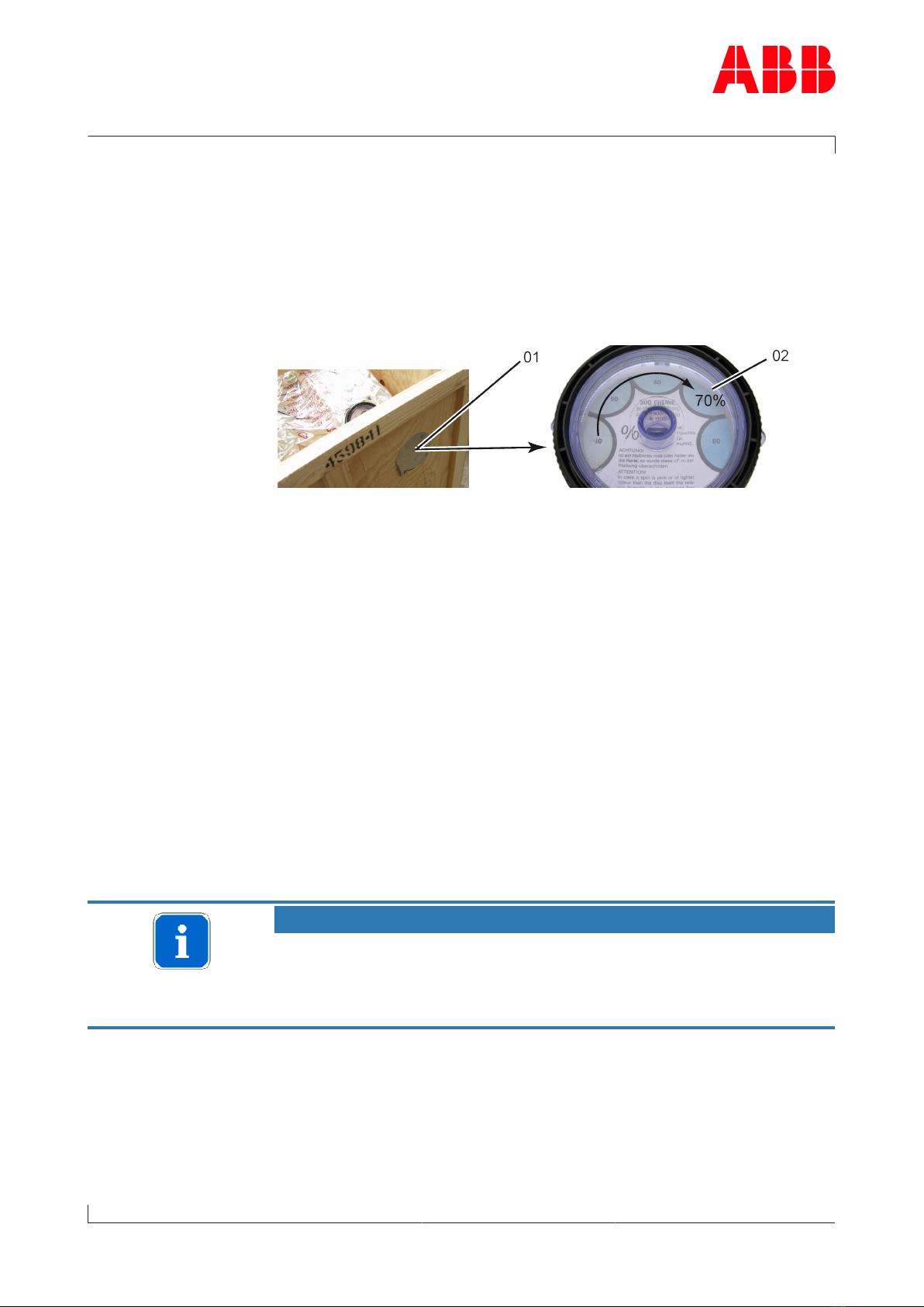
9.1 Possibilities for emergency repair............................................................................ 98
9.2 Locking the rotor.......................................................................................................... 99
9.3 Fit cover plate ............................................................................................................. 104
9.4 Blocking the inlets and outlets................................................................................ 108
9.5 Bypass the turbocharger .......................................................................................... 108
10 Mothballing the turbocharger ........................................................................... 109
10.1 Taking the engine out of operation for up to 12months.................................... 109
10.2 Taking the engine out of operation for more than 12months ........................... 111
11 Disposing of turbocharger components........................................................... 112
12 Spare parts............................................................................................................ 113
12.1 Ordering spare parts .................................................................................................. 113
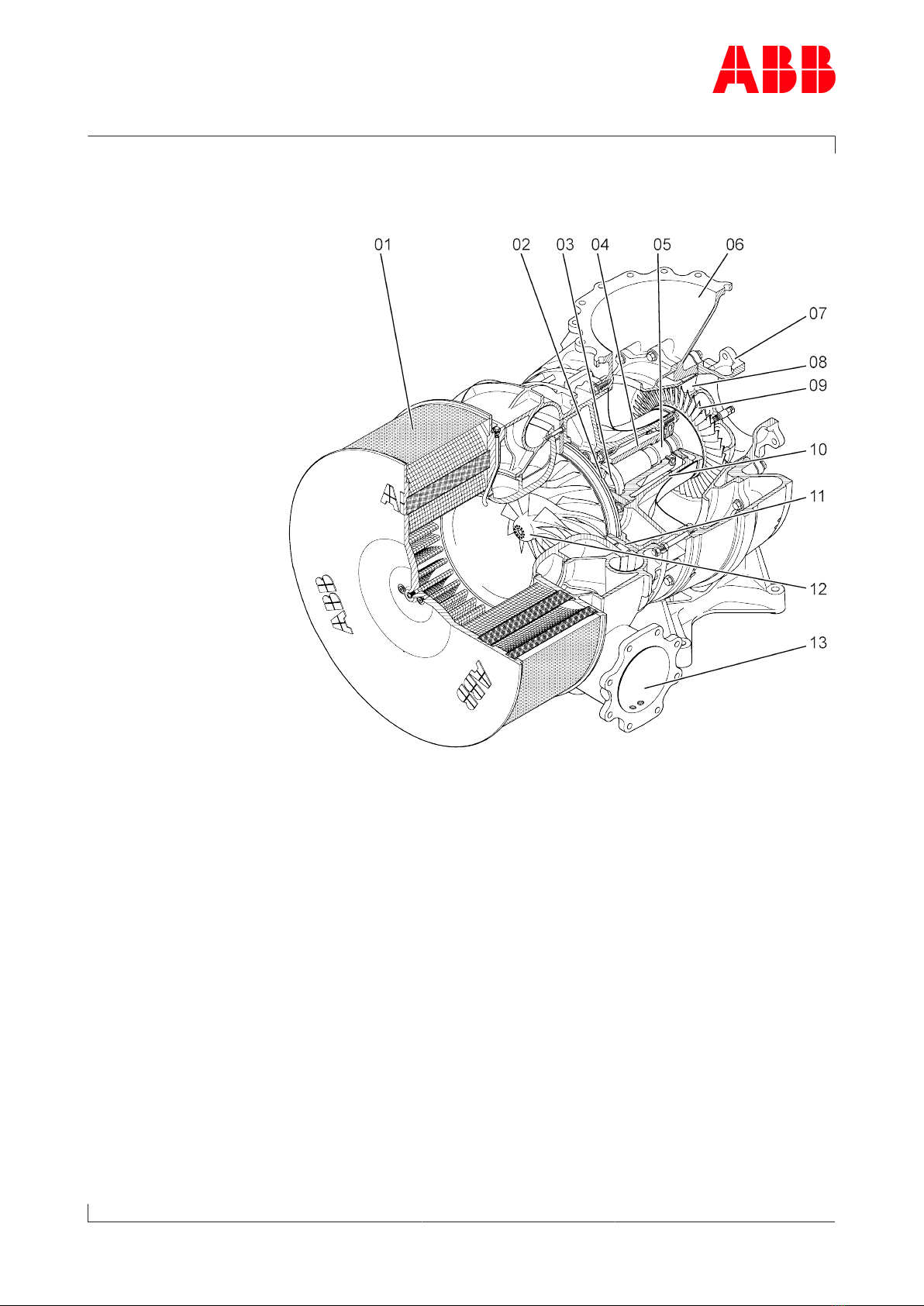
12.2 View of the turbocharger with part numbers ....................................................... 116
12.3 View of turbine cleaning system with part numbers (optional)........................ 118
12.4 View of cartridge group with part numbers TPL65-A.......................................... 120
12.5 View of cartridge group with part numbers TPL69-A.......................................... 122

Operation Manual / TPL65-A32 / -A33 / -A36 + TPL69-A32 / -A33
1 Preliminary remarks / 1.1 Purpose of this manual
© Copyright 2020 . All rights reserved. HZTL2498_EN Rev.F December 2020
1 Preliminary remarks
1.1 Purpose of this manual
This Operation Manual belongs to the turbocharger with the identical
serial number (01), see the cover sheet of the Operation Manual and the
turbocharger rating plate.
Operation Manual
This Operation Manual helps familiarise the user with the turbocharger
from ABB Turbocharging and how to use it as intended.
It provides important information in order that the turbocharger can be
operated safely, correctly and efficiently.
This Operation Manual complements and expands existing national reg-
ulations concerning work safety and accident prevention.
Target group
This Operation Manual is intended for engineers and qualified mechan-
ics who are responsible for operating the engine and the turbocharger
installed on it.
Availability of operation manual
An operation manual must be available at all times at the place where
the turbocharger is used.
Everyone who operates or works on the turbocharger must have first
read and understood the operation manual.
Page 3 / 123

Operation Manual / TPL65-A32 / -A33 / -A36 + TPL69-A32 / -A33
1 Preliminary remarks / 1.2 Layout and function
© Copyright 2020 . All rights reserved. HZTL2498_EN Rev.F December 2020
1.2 Layout and function
01Filter silencer 08Nozzle ring
02Radial plain bearing 09Turbine wheel
03Thrust bearing 10Bearing casing
04Bearing bush 11Diffuser
05Radial plain bearing 12Compressor wheel
06Gas outlet casing 13Compressor casing
07Gas inlet casing
Page 4 / 123

Operation Manual / TPL65-A32 / -A33 / -A36 + TPL69-A32 / -A33
1 Preliminary remarks / 1.2 Layout and function
© Copyright 2020 . All rights reserved. HZTL2498_EN Rev.F December 2020
Mode of operation
The turbocharger is a turbomachine and consists of the following main
components:
¡Turbine
¡Compressor
These are both mounted on a common shaft.
The exhaust gases from the diesel engine flow through the gas inlet cas-
ing (07) and nozzle ring (08) to the turbine wheel.
The turbine wheel (09) uses the energy contained in the exhaust gas to
drive the compressor wheel (12). The compressor then draws in fresh air,
compresses it and then forces it into the cylinders.
The exhaust gases escape to free air through an exhaust gas pipe which
is connected to the gas outlet casing (06).
The air which is necessary for operation of the diesel engine and is com-
pressed in the turbocharger is drawn through the suction branch or the
filter silencer (01) into the compressor wheel (12). This air then passes
through the diffuser (11) and leaves the turbocharger through the com-
pressor casing (13).
The rotor runs in two radial plain bearings (02/05). One plain bearing is
in the bearing bush (04), and the second one is in the axial thrust bearing
(03) at the compressor end.
The plain bearings are connected to a central lubricating oil duct which is
fed with oil from the engine's lubricating oil circuit. The oil outlet is al-
ways at the lowest point of the bearing casing (10).
Turbocharger version with compressor wheel cooling system
Depending on its range of use, the turbocharger is
provided with a compressor wheel cooling system. Com-
pressor wheel cooling means that, after the charge air
cooler at the engine end, cooled compressor air is de-
livered to the turbocharger to cool the compressor
wheel.
In view of the respective operating conditions, it is ab-
solutely essential that the compressor wheel is cooled in
order to guarantee its reliability and replacement inter-
vals. In the case of the turbocharger version with com-
pressor wheel cooling, the cooling air is supplied
through the side connection (15) in the bearing casing.
Page 5 / 123

Operation Manual / TPL65-A32 / -A33 / -A36 + TPL69-A32 / -A33
1 Preliminary remarks / 1.3 Intended use of the turbocharger
© Copyright 2020 . All rights reserved. HZTL2498_EN Rev.F December 2020
1.3 Intended use of the turbocharger
NOTICE
This turbocharger supplied by ABB Turbocharging has been developed
for use on diesel engines to generate the volume of air and the char-
ging pressure required to operate the engine.
The enginebuilder has provided ABB Turbocharging with information
regarding the intended use of the engine, from which the operating
limits specific to the turbocharger shown on the rating plate, such as
operating speeds, temperatures and replacement intervals, have been
derived.
Any other use is considered to be a special application, which must first
be clarified with ABB Turbocharging. The manufacturer accepts no liab-
ility for any other type of use. If the equipment is used for any other
purpose, ABB Turbocharging reserves the right to reject all warranty
claims.
State of the art This turbocharger was built according to state-of-the-art technology
and is operationally safe according to recognised safety regulations.
WARNING
Improper operation and maintenance of the turbocharger can result in
danger to life and limb of the user or third parties. In addition, im-
proper use may cause damage to the machine.
uThe machine may be operated only by trained personnel.
Use of the turbocharger as intended also includes observance of the in-
stallation / fitting, disassembly / removal, operating, maintenance / ser-
vicing and repair conditions specified by the manufacturer. Disposal reg-
ulations set down by local authorities must be observed.
Perfect condition The turbocharger may be installed only when in technically perfect condi-
tion while observing the instructions given in the engine builder's
manual. It may be used only for the intended purpose and operated in
compliance with the operation manual.
uMalfunctions which could affect safety must be eliminated immedi-
ately.
The manufacturer accepts no liability for any damage resulting from un-
authorised alterations to the turbocharger.
Page 6 / 123

Operation Manual / TPL65-A32 / -A33 / -A36 + TPL69-A32 / -A33
1 Preliminary remarks / 1.4 Storage of new turbochargers and spare
parts
© Copyright 2020 . All rights reserved. HZTL2498_EN Rev.F December 2020
1.4 Storage of new turbochargers and spare parts
Storage of new turbochargers and spare parts up to 6 months
New turbochargers and spare parts from ABB Turbocharging can be
stored in sealed packaging without additional mothballing measures for
up to 6months from the date of delivery (marked by the VCI label on the
package).
Volatile Corrosion Inhibitor (VCI)
Only dry rooms in which the relative humidity is between 40…70% and
no condensation can form are suitable for storage.
Storage of new turbochargers and spare parts for more than 6
months (VCI)
WARNING
Protection of health when handling VCIs
VCI products are not hazardous in the sense of the Hazardous Sub-
stances Ordinance. Nevertheless, the following points are to be ob-
served when handling VCIs:
uEnsure good room ventilation.
uDo not eat, drink or keep food at the workplace while working with
VCIs.
uWear safety gloves.
uClean hands and face after working with VCIs.
uFor further information refer to www.branopac.com.
Wear safety gloves to protect against chemical hazards.
The following mothballing measures are required every 6months:
uOpen the package.
uRemove the VCI corrosion protection emitter from the package and
replace it with a new, identical VCI corrosion protection emitter. New
VCI corrosion protection emitters can be obtained at www.brano-
pac.com.
uDispose of the old VCI corrosion protection emitter in an environ-
mentally compatible manner, professionally and in accordance with
local regulations.
Page 7 / 123

Operation Manual / TPL65-A32 / -A33 / -A36 + TPL69-A32 / -A33
1 Preliminary remarks / 1.4 Storage of new turbochargers and spare
parts
© Copyright 2020 . All rights reserved. HZTL2498_EN Rev.F December 2020
uSeal the package. The better the external seal is designed, the more
permanent the protection.
Long-term storage of turbochargers
The turbochargers will be prepared for prolonged storage by ABB Tur-
bocharging on request. The package is equipped with a hygrometer (see
illustration).
The following measures are required every 6months:
uCheck the hygrometer(02) in the sight-glass. There is an opening(01)
in the wooden crate which allows this check to be carried out. When
the display field has changed colour at the 70% level, the maximum
permissible humidity has been exceeded. In this case, the turbochar-
ger must be inspected by an ABB Turbocharging Service Station and
repacked.
uInspect the package for damage. If the package is damaged, the tur-
bocharger must be inspected by an ABB Turbocharging Service Sta-
tion and repacked.
After every 3 years the following work steps must be performed by an
ABB Turbocharging Service Station:
¡Inspect the component
¡Replace the desiccant agent
¡Repackage the component.
NOTICE
Turbocharger ready for operation
If the 70% field of the hygrometer(02) has not changed colour and the
package is undamaged, the turbocharger can be put into operation
without any prior inspection by an ABB Turbocharging Service Station.
Unpacking the turbochargers
The corrosion protection effect ends after the material is unpacked from
the VCI package.
To avoid the formation of condensation, the surroundings and the con-
tent of the package must have the same temperature during unpacking.
Page 8 / 123

Operation Manual / TPL65-A32 / -A33 / -A36 + TPL69-A32 / -A33
1 Preliminary remarks / 1.5 Essential information
© Copyright 2020 . All rights reserved. HZTL2498_EN Rev.F December 2020
1.5 Essential information
Organisational measures
In addition to the Operation Manual, the general statutory regulations
for the prevention of accidents and protection of the environment are
also to be observed.
This also applies for the provision and wearing of personal protective
equipment.
NOTICE
The manner in which personnel work on and with the turbocharger with
regard to safety and risks is to be checked on a regular basis in accord-
ance with the Operation Manual.
uIf the turbocharger shows modifications affecting safety or any cor-
responding operating behaviour, it must be shut down immediately
by stopping the engine. The malfunction must be reported to the per-
son or department responsible.
NOTICE
Any modifications, additions or conversions made to the turbocharger
that could impair safety require the prior approval of ABB Turbochar-
ging.
Page 9 / 123

Operation Manual / TPL65-A32 / -A33 / -A36 + TPL69-A32 / -A33
1 Preliminary remarks / 1.5 Essential information
© Copyright 2020 . All rights reserved. HZTL2498_EN Rev.F December 2020
Original parts and safety
Original parts and accessories are specially designed for the turbochar-
ger supplied by ABB.
WARNING
Use original parts
Operation of the turbocharger with non-original parts can impair the
safety of the turbocharger and can cause serious damage to property
and injury to personnel.
uOnly use original parts from ABB.
ABB accepts no liability for any damage resulting from the use of non-
original parts and corresponding accessories.
Competence of personnel
The turbocharger must only be operated and serviced by trained and au-
thorised personnel. Basic mechanical training is a prerequisite.
Design variants
This document is valid for different design variants of turbochargers.
There may be sections and descriptions of components that are not rel-
evant for a specific turbocharger variant.
ABB Turbocharging Service Stations will be happy to provide information
on questions regarding a design variant (see Contact information at
www.abb.com/turbocharging).
Accuracy of illustrations
The illustrations in this document are general in nature and intended for
ease of understanding. Differences in detail are therefore possible.
Registered trademarks
Registered trademarks of external companies are used in this document.
The trademarks are marked with ®.
Page 10 / 123

Operation Manual / TPL65-A32 / -A33 / -A36 + TPL69-A32 / -A33
1 Preliminary remarks / 1.6 Symbols and definitions
© Copyright 2020 . All rights reserved. HZTL2498_EN Rev.F December 2020
1.6 Symbols and definitions
The following symbols are used in the documents:
wPrerequisite
uWork step
¡Enumeration, first level
- Enumeration, second level
→ Refers to a page number
Definition of notes
NOTICE
Note
A note provides suggestions which facilitate the work on the product.
Definition of mandatory signs
Mandatory signs show the protective equipment to be worn for a task.
The mandatory signs are described in chapter Safety and must be com-
plied with.
Definition of caution / warning
The caution and warning signs are described in the chapter Safety.
ABB Turbocharging
ABB Switzerland Ltd, Turbocharging is identified as ABB Turbocharging
in this document.
Official service stations of ABB Turbocharging
Official service stations are regularly audited and certified by ABB Tur-
bocharging. See also chapter Contact information →13.
Page 11 / 123

Operation Manual / TPL65-A32 / -A33 / -A36 + TPL69-A32 / -A33
1 Preliminary remarks / 1.7 Turbocharger rating plate
© Copyright 2020 . All rights reserved. HZTL2498_EN Rev.F December 2020
1.7 Turbocharger rating plate
Operating limits 01 Turbocharger operating limits at engine overload (110%).
Only when operating in the test rig unless otherwise agreed with the
enginebuilder.
02 Turbocharger operating limits during operation
Recommended replace-
ment intervals for tur-
bocharger components
03 Replacement interval for plain bearings in 1000 h
04 Replacement interval for compressor in 1000 h
05 Replacement interval for turbine in 1000 h
Further information 06 Part number for customer
07 Designation of special design
08 Turbocharger weight in kg
09 Turbocharger type
10 Serial number
11 Year of turbocharger construction
12 Manufacturing plant
Page 12 / 123

Operation Manual / TPL65-A32 / -A33 / -A36 + TPL69-A32 / -A33
1 Preliminary remarks / 1.8 Contact information
© Copyright 2020 . All rights reserved. HZTL2498_EN Rev.F December 2020
1.7.1 Explanation of the rating plate
The recommended replacement intervals and the corresponding opera-
tional limits are jointly defined with the engine manufacturer. This in-
formation is specific to the system.
Operation above the indicated values nBmax, tBmax can considerably shorten
the recommended replacement intervals. In such cases, we recommend that
you contact the nearest official ABB Turbocharging service station.
nMmaxand tMmax normally apply only when running at overload (110%) during
trials on the engine test bed. Operation above nMmax and tMmax is not permit-
ted.
Non-observance of the recommended replacement intervals increases the
risk of unpredictable component failures.
1.7.2 Positions of the rating plates
A rating plate is attached to the turbocharger foot, one on the left and
one on the right. On turbochargers with insulation from ABB, at least one
additional rating plate is attached to the insulation of the gas outlet cas-
ing.
1.8 Contact information
Contact information for the official service stations of ABB Turbochar-
ging is available online.
uScan the QR code to access our website.
ABB Switzerland Ltd, Turbocharging
Bruggerstrasse 71a
CH-5401 Baden
Switzerland
www.abb.com/turbocharging
Page 13 / 123

Operation Manual / TPL65-A32 / -A33 / -A36 + TPL69-A32 / -A33
2 Safety / 2.1 Introduction
© Copyright 2020 . All rights reserved. HZTL2498_EN Rev.F December 2020
2 Safety
2.1 Introduction
Turbochargers manufactured by ABB are state of the art and comply
with the pertinent safety and health-protection requirements that ap-
plied when the turbocharger was manufactured. Consequently, the tur-
bocharger is safe to operate. Nevertheless, during turbocharger opera-
tion and when working on the turbocharger, residual risks can exist
which:
¡originate from the turbocharger itself and its accessories
¡originate from the operating and auxiliary materials used
¡are the consequence of insufficient observance of the safety instruc-
tions
¡are the consequence of unsatisfactory and improper execution of
maintenance and inspection work.
The operating company is responsible for access to the turbocharger as
well as the organisational measures that regulate the safe handling of
the turbocharger by its personnel.
All instructions contained in this chapter must be observed for safe and
trouble-free operation of the turbocharger and during all work on the
turbocharger.
All further safety instructions contained and specifically identified in
every chapter of this manual (see section Definition of Safety Instruc-
tions) must also be observed.
2.2 CE conformity
Information
ABB turbochargers fulfil Directive 2006/42/EC on machinery and are
considered partly completed machinery in the sense of Article 2 g.
Page 14 / 123

Operation Manual / TPL65-A32 / -A33 / -A36 + TPL69-A32 / -A33
2 Safety / 2.3 Definition of mandatory signs
© Copyright 2020 . All rights reserved. HZTL2498_EN Rev.F December 2020
2.3 Definition of mandatory signs
To be worn at all times
Protective clothing Safety footwear to pro-
tect against mechanical
hazard and risk of fall-
ing
To be worn according to the specific work
Safety glasses Safety goggles
Safety gloves against
- Mechanical hazard
- Chemical hazard
- Thermal hazard
Respiratory mask
against
- Dusts
- Gases
Safety helmet Ear protection
2.4 Definition of Safety instructions
The following symbols and terms used in this manual concern safety or
refer to possible hazards:
WARNING
Definition of warning
Serious personal injuries and even accidents with fatal consequences
may occur if work and operating instructions marked with this symbol
and the word WARNING are either not followed or not followed pre-
cisely.
uWarning signs must be observed at all times.
CAUTION
Definition of caution
Serious machine or property damage may occur if work and operating
instructions marked with this symbol and the word CAUTION are either
not followed or not followed precisely.
uCaution signs must be observed at all times.
Page 15 / 123

Operation Manual / TPL65-A32 / -A33 / -A36 + TPL69-A32 / -A33
2 Safety / 2.5 Warning plates on the turbocharger
© Copyright 2020 . All rights reserved. HZTL2498_EN Rev.F December 2020
2.5 Warning plates on the turbocharger
Warning plates that must be observed are attached to the turbocharger.
The warning plates must always be present in the intended locations
and must be legible.
Fig.1: Warning plate
Part number Size [mm] Product
81080 105 x 74 TPL
When uninsulated turbochargers are delivered to the engine builder, the
warning plates must be subsequently attached to the insulation. This is
the responsibility of the engine builder.
Page 16 / 123

Operation Manual / TPL65-A32 / -A33 / -A36 + TPL69-A32 / -A33
2 Safety / 2.6 Safe operation and maintenance
© Copyright 2020 . All rights reserved. HZTL2498_EN Rev.F December 2020
2.6 Safe operation and maintenance
The instructions specified in this section are for the safety of personnel.
Together with the instructions in the Hazards during operation and
maintenance section, they allow the user to safely use the turbocharger.
Work safety and work area safety
WARNING
Risk of falling
There is the risk that someone can fall when working on the turbochar-
ger.
uDo not climb on the turbocharger or on parts attached to it or use
these as climbing aids.
uWhen working at levels above the head, use climbing aids and work
platforms suitable for this purpose.
uObserve all general regulations for the prevention of accidents.
uDo not work on the turbocharger if you are under physical or mental
stress.
uWork only with suitable tools as well as equipment and working ma-
terials that are in perfect condition.
uElectric tools must be solidly earthed, and connecting cables may not
be damaged.
uKeep the workplace clean, clear away loose objects and remove
obstacles on the floor.
uKeep the floor, equipment and the turbocharger clean.
uHave oil binding materials ready at hand and keep oil catch pans
ready or in position
uEliminate leaks.
uKeep fire-protection materials and fire-extinguishing equipment
ready.
Welding work close to the turbocharger
uIf welding work is being carried out in the vicinity of the turbocharger,
cover the filter silencer so that the filter mat is not damaged.
uRemove combustible objects and substances out of the range of fly-
ing sparks.
uCover all connections on the turbocharger so that no foreign objects
can get into the turbocharger.
uWear personal protective equipment (PPE) for welding operations.
Page 17 / 123

Operation Manual / TPL65-A32 / -A33 / -A36 + TPL69-A32 / -A33
2 Safety / 2.6 Safe operation and maintenance
© Copyright 2020 . All rights reserved. HZTL2498_EN Rev.F December 2020
Safety during start-up / commissioning and operation
uBefore starting work, carry out visual inspection of working area.
uRemove any obstacles and objects lying around.
uBefore start-up / commissioning, check all pipes from and to tur-
bocharger for damage and leaks.
uDon't work in any way that could impair safety when working on tur-
bocharger.
uAfter about every 12 hours of operation or at least once a day, inspect
turbocharger for visible damage and defects.
uImmediately report any damage or changes in operational perform-
ance to person responsible.
uIf damage is discovered, immediately shut down turbocharger and se-
cure it against inadvertent or unauthorized use.
uWhen switching on auxiliary power sources (hydraulics, pneumatics,
electricity, water), keep an eye open for any hazards resulting from
supplying these power sources.
Safety during cleaning
If cleaning agents or solvents are used for cleaning, the corresponding
material safety data sheet and the safety instructions in section "Haz-
ards due to operating and auxiliary materials" must be observed.
uObserve the material safety data sheet for the cleaning agent or
solvent.
uWear personal protective equipment (PPE) according to the material
safety data sheet.
uInspect the electric cables for abrasion and damage before and after
your cleaning work.
Page 18 / 123
Other manuals for TPL65-A33
1
Table of contents
Other ABB Air Compressor manuals
Popular Air Compressor manuals by other brands

Hitachi
Hitachi WHP09500AEDPC9EQ instruction manual

Sullair
Sullair 3000P user manual

Metabo HPT
Metabo HPT EC2510E Instruction manual and safety instructions

Prs
Prs MARY CRIES instruction manual

Campbell Hausfeld
Campbell Hausfeld IRONFORCFe WL6500 series operating instructions

ROTORCOMP
ROTORCOMP NK 100 operating manual