ABB TPL65VA32 User manual

Operation Manual
ABB Turbocharging
Type TPL65VA32 HT596416
nMmax 499 t Mmax 680
nBmax 475 t Bmax 650
1/s °C
01210 35 50 50
Year 2020 Application according to
the Operation Manual
kg
HZTL2464 English
TPL65VA32
Original Operation Manual

Operating condition and replacement intervals
The operational limits for the turbocharger nBmax, tBmax, nMmax, tMmax, inspection- and replacement intervals for the compon-
ents concerned on the rating plate are valid for the operational mode and compressor inlet condition, which has been agreed upon
between the engine builder and ABB.
Note: Replacement intervals of components depends on the load profile, turbine inlet temperature, suction air temperature and
turbocharger speed. In case the operation conditions differs significantly from what is considered to be normal for the cur-
rent application, it is recommended to contact ABB for a re-calculation of replacement intervals. Frequent load alterations,
high temperatures and high speed lower the life of components.
Unless otherwise agreed, the application limits nMmax, tMmax are valid for the test operation for a limited time.

Operation Manual / TPL65VA32 / VA33
Table of contents
© Copyright 2020 . All rights reserved. HZTL2464_EN Rev.E March 2020
Operation Manual
1 Preliminary remarks................................................................................................. 3
1.1 Purpose of this manual .................................................................................................. 3
1.2 Layout and function........................................................................................................ 4
1.3 Intended use of the turbocharger .............................................................................. 7
1.4 Storage of new turbochargers and spare parts ....................................................... 8
1.5 Essential information................................................................................................... 10
1.6 Symbols and definitions .............................................................................................. 13
1.7 Turbocharger rating plate ........................................................................................... 14
1.8 Contact information..................................................................................................... 15
2 Safety...................................................................................................................... 16
2.1 Introduction ................................................................................................................... 16
2.2 CE conformity ................................................................................................................ 16
2.3 Definition of mandatory signs ................................................................................... 17
2.4 Definition of Safety instructions ............................................................................... 17
2.5 Warning plates on the turbocharger......................................................................... 18
2.6 Safe operation and maintenance............................................................................... 18
2.7 Hazards during operation and maintenance........................................................... 21
2.8 Periodic checking of the pressure vessel ................................................................. 27
2.9 Lifting loads ................................................................................................................... 27
3 Commissioning...................................................................................................... 29
3.1 Oil supply ........................................................................................................................ 29
3.2 Inspection work............................................................................................................. 32
3.3 Commissioning after taking out of operation........................................................ 33
4 Operation ............................................................................................................... 35
4.1 Noise emissions ............................................................................................................ 35
4.2 Servicing work ............................................................................................................... 36
4.3 Replacement intervals for turbocharger components.......................................... 38
4.4 Speed measurement ................................................................................................... 40
4.5 Emergency operation TPL..VA ................................................................................... 44
4.6 Stopping the engine .................................................................................................... 45
5 Maintenance .......................................................................................................... 47
5.1 Foreword to Maintenance ........................................................................................... 47
5.2 Cleaning the filter silencer.......................................................................................... 48
5.3 Cleaning the compressor during operation ............................................................ 51
5.4 Cleaning turbines and guide vanes during operation ........................................... 55
5.5 Cleaning components mechanically.......................................................................... 55

Operation Manual / TPL65VA32 / VA33
Table of contents
© Copyright 2020 . All rights reserved. HZTL2464_EN Rev.E March 2020
6 Troubleshooting.................................................................................................... 64
6.1 Malfunctions when starting....................................................................................... 64
6.2 Surging of the turbocharger...................................................................................... 64
6.3 Malfunctions during operation ................................................................................. 66
6.4 Malfunctions when stopping ..................................................................................... 68
6.5 Speed measurement system ..................................................................................... 69
6.6 Variable Turbine Geometry ........................................................................................ 69
7 Removal and installation....................................................................................... 71
7.1 Turbocharger weights.................................................................................................. 71
7.2 Removing the turbocharger........................................................................................ 71
7.3 Installing the turbocharger ......................................................................................... 73
8 Disassembly and assembly .................................................................................. 74
8.1 Introduction ................................................................................................................... 74
8.2 Module weights ............................................................................................................. 75
8.3 Removing and fitting filter silencer or air suction branch.................................... 77
8.4 Axial clearance ............................................................................................................... 79
8.5 Removing cartridge group .......................................................................................... 79
8.6 Removing and fitting turbine diffuser..................................................................... 84
8.7 Removing variable turbine geometry module with gas inlet casing .................. 85
8.8 Fitting the variable turbine geometry module and the gas inlet casing .......... 86
8.9 Installing cartridge group............................................................................................ 87
8.10 Table of tightening torques........................................................................................ 93
9 Taking out of operation at short notice ............................................................ 95
9.1 Possibilities for emergency repair............................................................................. 95
9.2 Fit cover plate ............................................................................................................... 96
9.3 Blocking the inlets and outlets.................................................................................. 99
9.4 Bypass the turbocharger ............................................................................................ 99
10 Mothballing the turbocharger ........................................................................... 101
10.1 Taking the engine out of operation for up to 12months.................................... 101
10.2 Taking the engine out of operation for more than 12months .......................... 102
11 Disposing of turbocharger components.......................................................... 104
12 Spare parts........................................................................................................... 105
12.1 Ordering spare parts .................................................................................................. 105
12.2 View of turbocharger with part numbers .............................................................. 107
Operation Manual / TPL65VA32 / VA33
1 Preliminary remarks / 1.1 Purpose of this manual
© Copyright 2020 . All rights reserved. HZTL2464_EN Rev.E March 2020
1 Preliminary remarks
1.1 Purpose of this manual
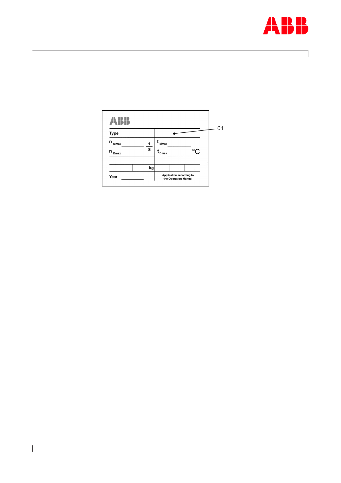
This Operation Manual belongs to the turbocharger with the identical
serial number (01), see the cover sheet of the Operation Manual and the
turbocharger rating plate.
Operation Manual
This Operation Manual helps familiarise the user with the turbocharger
from ABB Turbocharging and how to use it as intended.
It provides important information in order that the turbocharger can be
operated safely, correctly and efficiently.
This Operation Manual complements and expands existing national reg-
ulations concerning work safety and accident prevention.
Target group
This Operation Manual is intended for engineers and qualified mechan-
ics who are responsible for operating the engine and the turbocharger
installed on it.
Availability of operation manual
An operation manual must be available at all times at the place where
the turbocharger is used.
Everyone who operates or works on the turbocharger must have first
read and understood the operation manual.
Page 3 / 108

Operation Manual / TPL65VA32 / VA33
1 Preliminary remarks / 1.2 Layout and function
© Copyright 2020 . All rights reserved. HZTL2464_EN Rev.E March 2020
1.2 Layout and function
01Filter silencer 08Nozzle ring
02Radial plain bearing 09Turbine wheel
03Thrust bearing 10Bearing casing
04Bearing bush 11Diffuser
05Radial plain bearing 12Compressor wheel
06Gas outlet casing 13Air outlet casing
07Gas inlet casing
Page 4 / 108

Operation Manual / TPL65VA32 / VA33
1 Preliminary remarks / 1.2 Layout and function
© Copyright 2020 . All rights reserved. HZTL2464_EN Rev.E March 2020
Mode of operation
The turbocharger is a turbomachine and consists of the following main
components:
¡Turbine
¡Compressor
These are both mounted on a common shaft.
The exhaust gases from the diesel engine flow through the gas inlet cas-
ing (07) and nozzle ring (08) to the turbine wheel.
The turbine wheel (09) uses the energy contained in the exhaust gas to
drive the compressor wheel (12). The compressor then draws in fresh air
and forces precompressed air into the cylinders.
The exhaust gases escape to free air through an exhaust gas pipe which
is connected to the gas outlet casing (06).
The air which is necessary for operation of the diesel engine and is com-
pressed in the turbocharger is drawn through the suction branch or the
filter silencer (01) into the compressor wheel (12). It then passes through
the diffuser (11) and leaves the turbocharger through the air outlet cas-
ing (13).
The rotor runs in two radial plain bearings (02/05). One plain bearing is
in the bearing bush (04), and the second one is in the axial thrust bearing
(03) at the compressor end.
The plain bearings are connected to a central lubricating oil duct which is
fed with oil from the engine's lubricating oil circuit. The oil outlet is al-
ways at the lowest point of the bearing casing (10).
Turbocharger version with compressor wheel cooling system
Depending on its range of use, the turbocharger is
provided with a compressor wheel cooling system. Com-
pressor wheel cooling means that, after the charge air
cooler at the engine end, cooled compressor air is de-
livered to the turbocharger to cool the compressor
wheel.
In view of the respective operating conditions, it is ab-
solutely essential that the compressor wheel is cooled in
order to guarantee its reliability and replacement inter-
vals. In the case of the turbocharger version with com-
pressor wheel cooling, the cooling air is supplied
through the side connection (15) in the bearing casing.
Page 5 / 108

Operation Manual / TPL65VA32 / VA33
1 Preliminary remarks / 1.2 Layout and function
© Copyright 2020 . All rights reserved. HZTL2464_EN Rev.E March 2020
Additional function TPL..V.
These turbocharger types have adjustable guide vanes at the turbine
end instead of a nozzle ring.
Page 6 / 108

Operation Manual / TPL65VA32 / VA33
1 Preliminary remarks / 1.3 Intended use of the turbocharger
© Copyright 2020 . All rights reserved. HZTL2464_EN Rev.E March 2020
1.3 Intended use of the turbocharger
NOTICE
This turbocharger supplied by ABB Turbocharging has been developed
for use on diesel engines to generate the volume of air and the char-
ging pressure required to operate the engine.
The enginebuilder has provided ABB Turbocharging with information
regarding the intended use of the engine, from which the operating
limits specific to the turbocharger shown on the rating plate, such as
operating speeds, temperatures, exchange intervals / replacement in-
tervals, have been derived.
Use in connection with a gas engine requires that the engine is not in-
stalled in a potentially explosive environment and that precautions are
taken to ensure that the engine room as a whole is classified as non-ex-
plosive.
Any other use is considered to be a special application, which must first
be clarified with ABB Turbocharging. The manufacturer accepts no liab-
ility for any other type of use. If the equipment is used for any other
purpose, ABB Turbocharging reserves the right to reject all warranty
claims.
State of the art This turbocharger was built according to state-of-the-art technology
and is operationally safe according to recognised safety regulations.
WARNING
Improper operation and maintenance of the turbocharger can result in
danger to life and limb of the user or third parties. In addition, im-
proper use may cause damage to the machine.
uThe machine may be operated only by trained personnel.
Use of the turbocharger as intended also includes observance of the in-
stallation / fitting, disassembly / removal, operating, maintenance / ser-
vicing and repair conditions specified by the manufacturer. Disposal reg-
ulations set down by local authorities must be observed.
Perfect condition The turbocharger may be installed only when in technically perfect condi-
tion while observing the instructions given in the engine builder's
manual. It may be used only for the intended purpose and operated in
compliance with the operation manual.
uMalfunctions which could affect safety must be eliminated immedi-
ately.
The manufacturer accepts no liability for any damage resulting from un-
authorised alterations to the turbocharger.
Page 7 / 108

Operation Manual / TPL65VA32 / VA33
1 Preliminary remarks / 1.4 Storage of new turbochargers and spare
parts
© Copyright 2020 . All rights reserved. HZTL2464_EN Rev.E March 2020
1.4 Storage of new turbochargers and spare parts
Storage of new turbochargers and spare parts up to 6 months
New turbochargers and spare parts from ABB Turbocharging can be
stored in sealed packaging without additional mothballing measures for
up to 6months from the date of delivery (marked by the VCI label on the
package).
Volatile Corrosion Inhibitor (VCI)
Only dry rooms in which the relative humidity is between 40…70% and
no condensation can form are suitable for storage.
Storage of new turbochargers and spare parts for more than 6
months (VCI)
WARNING
Protection of health when handling VCIs
VCI products are not hazardous in the sense of the Hazardous Sub-
stances Ordinance. Nevertheless, the following points are to be ob-
served when handling VCIs:
uEnsure good room ventilation.
uDo not eat, drink or keep food at the workplace while working with
VCIs.
uWear safety gloves.
uClean hands and face after working with VCIs.
uFor further information refer to www.branopac.com.
Wear safety gloves to protect against chemical hazards.
The following mothballing measures are required every 6months:
uOpen the package.
uRemove the VCI corrosion protection emitter from the package and
replace it with a new, identical VCI corrosion protection emitter. New
VCI corrosion protection emitters can be obtained at www.brano-
pac.com.
uDispose of the old VCI corrosion protection emitter in an environ-
mentally compatible manner, professionally and in accordance with
local regulations.
Page 8 / 108
Table of contents
Other ABB Air Compressor manuals


