ABB NGC8206 User guide

MEASUREMENT & CONTROL SYSTEMS
NGC8206 Start-Up Guide

Intellectual Property & Copyright Notice
©2010 by ABB Inc., Totalflow Products (“Owner”), Bartlesville,
Oklahoma 74006, U.S.A. All rights reserved.
Any and all derivatives of, including translations thereof, shall remain
the sole property of the Owner, regardless of any circumstances.
The original US English version of this manual shall be deemed the
only valid version. Translated versions, in any other language, shall
be maintained as accurately as possible. Should any discrepancies
exist, the US English version will be considered final. ABB is not
liable for any errors and omissions in the translated materials.
Notice: This publication is for information only. The contents are
subject to change without notice and should not be construed as a
commitment, representation, warranty, or guarantee of any method,
product, or device by Owner.
Inquiries regarding this manual should be addressed to ABB Inc.,
Totalflow Products, Technical Communications, 7051 Industrial
Blvd., Bartlesville, Oklahoma 74006, U.S.A.
Introduction
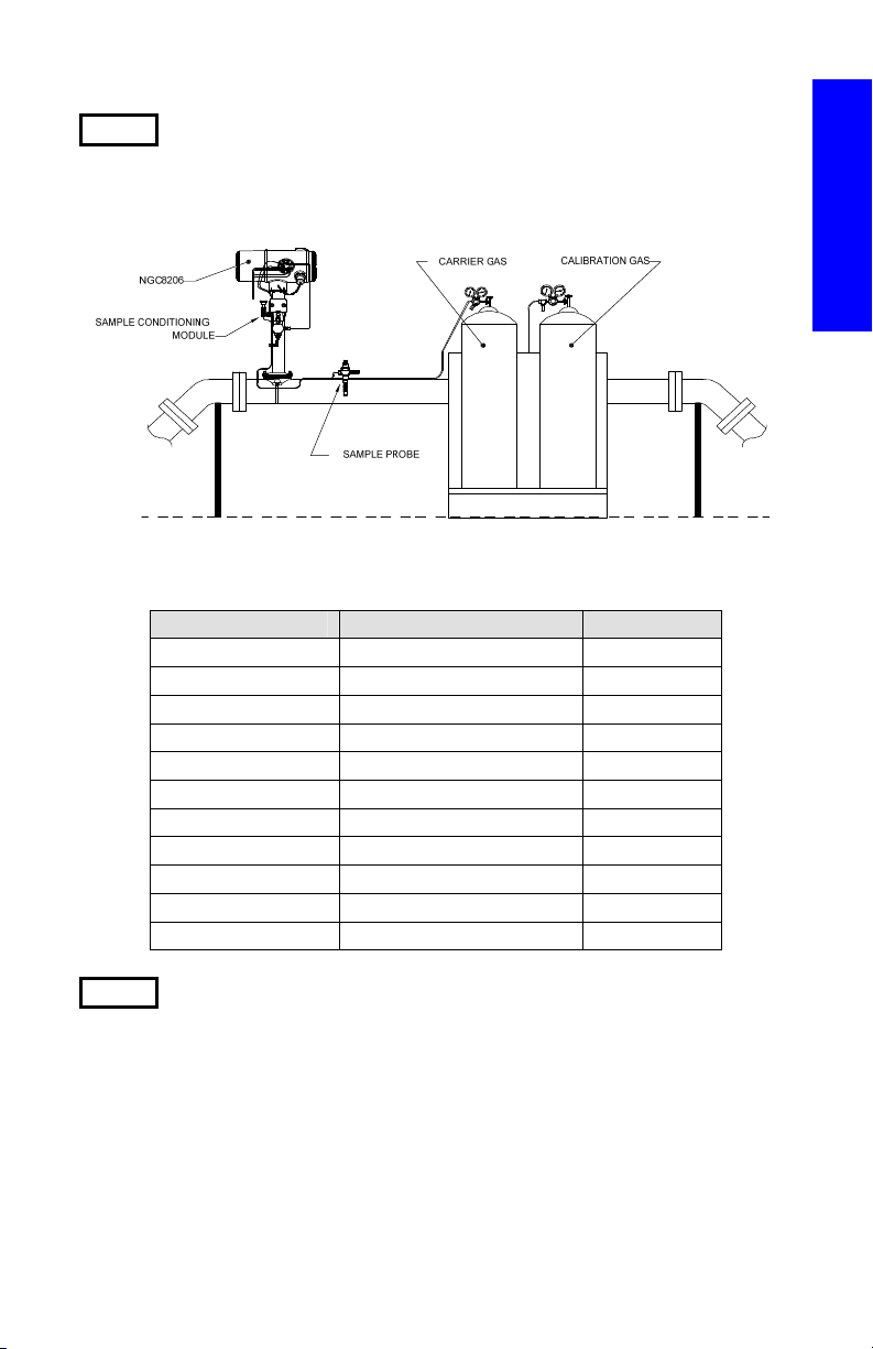
This is a quick start guide designed for typical installations only. It is
recommended that inexperienced technicians consult the Totalflow
NGC8206 User’s Manual for more detailed information while performing
the installation and start-up. Scan through the guide to see what
information is available before beginning the installation. If there are
questions that are not answered in this guide or other documentation, the
user should call their local Totalflow representative, or call the number
listed on the back of this guide. Although there are alternate methods of
installation, it is recommended that technicians perform these
procedures in the presented order.
Unpack and inspect the NGC8206 and optional equipment, if purchased.
Inspect all parts and pieces for damage and missing or incorrect
components.
Before Beginning
The NGC may be configured with a multitude of optional equipment.
Please see the NGC8206 User’s Manual for optional equipment
installation instructions.
If the Optional Equipment Unit (OEU) was purchased to house the power
supply, battery and/or communications, this should be installed in a
Division 2 or general purpose area prior to the NGC installation. Specific
instructions may also be found in the NGC8206 User’s Manual.
Communication wiring information is presented in this guide.

1
Basic Installation
Step 1 Locate Suitable Installation Site
The NGC should be located close to the sample probe in an effort to
minimize the sample line length. See the table below for transport tubing
distances and lag times.
1/8” Transport Tubing Lag Time Considerations
Distance Conditioning Module Seconds
10’ (3.05 m) 2102023-XXX 36
20’ (6.10 m) 2102023-XXX 48
30’ (9.14 m) 2102023-XXX 60
50’ (15.20 m) 2102024-XXX 16
100’ (30.48 m) 2102024-XXX 23
150’ (45.72 m) 2102024-XXX 30
200’ (60.10 m) 2102024-XXX 36
250’ (76.20 m) 2102024-XXX 42
300’ (91.44 m) 2102024-XXX 50
350’ (106.68 m) 2102024-XXX 56
380’ (115.82 m) 2102024-XXX 60
Step 2 Mount the Unit
Mount the unit on a meter run, wall shelf, stand-alone pipe or inside a
cold weather enclosure.
NOTE: The NGC should not be connected to any section of pipeline
where cathodic protection exists.
The NGC has a grounding lug on the mounting neck of the enclosure.
This lug should be tied to a good earth ground with no smaller than
#12AWG wire.
Installation

2
COLD WEATHER
ENCLOSURE MOUNTED
WALL SHELF MOUNTING
WALL SHELF
STAND-ALONE PIPE MOUNTED
PIPE RUN MOUNTED
PIPE
SADDLE
2" MOUNTING
PIPE
CWE
MOUNTING
PLATE
OPTIONAL
MOUNTING PIPE
W/FLANGE
Step 3 Install the Sample Conditioning Bracket and Sample
Conditioning Modules, and Connect to Feed-Through
Assembly
IMPORTANT: A particulate filter with a liquid/vapor separator sample
conditioning module is strongly recommended. Operating the NGC
without a sample conditioning module can allow liquids and particulates
to contaminate columns. This can damage the unit and void the
warranty.
If none are required, connections are made directly to the feed-through
assembly.
3A Mount the sample conditioning bracket on the pipe.
2" Pipe
U-Bolt
VIEW A-A
AAAA
B
B
VIEW B-B
SINGLE MODULE BRACKET MULTIPLE MODULE BRACKET
Installation

3
3B Mount the sample
conditioning module on the
sample conditioning bracket.
Step 4 Install the Sample Probe(s)
Totalflow strongly suggests a temperature compensating pressure
regulating sample probe be used. Refer to any manufacturer’s
recommendations supplied with the probe. If the sample probe is to be
mounted in a section of pipe where cathodic currents exist, the user
should install isolators in the sample tubing between the probe and the
NGC.
NOTE: API 14.1 recommends using a Strouhal number to determine
probe lengths. This reduces the effects of resonant vibration.
Please refer to API standards for additional information.
Step 5 Connect Sample Streams
IMPORTANT: Remove sealing screws from the input ports to connect
the tubing. Unused ports MUST remain sealed to keep
moisture from entering the manifold and potentially
damaging the instrument.
5A Connect the tubing
between the sample
probe and conditioning
module. See Precautions
below.
5B Connect the tubing between
the conditioning module and
feed-through assembly.
Purge sample gas through
tubing during connection.
SAMPLE CONDITIONING
U-BOLT
SAMPLE CONDITIONING MODULE
SYSTEM MOUNTING BRACKET
Installation

4
Precautions:
•DO NOT use any type of plastic, Teflon or Teflon-lined
braided steel tubing. Use only good quality, clean stainless
steel chromatographic grade transport tubing for carrier,
calibration gas and sample lines. Use of poor quality stainless
steel tubing will generate unsatisfactory results.
•Use only high purity 99.995% grade helium or better for carrier.
•Sample Transport Tubing Lengths: When sample conditioning
modules are used, the sample transport tubing run can be up to
50 feet. Lengths longer than 50 feet must adhere to the rules of
calculated lag time per the Calculating Lag Time section in the
System Description chapter of the NGC8206 User’s Manual.
If a sample conditioning module is not being used, the sample
transport tubing should be 1/16-inch tubing and no longer than
ten feet.
•Purge all lines prior to connecting to the NGC.
•Suggested calibration blend component concentrations:
Component % Blend Component % Blend Component % Blend
N2 2.5% C3 1.0% iC5 0.1%
CO2 1.0% iC4 0.3% nC5 0.1%
C1 89.57% nC4 0.3% C6 0.03%
C2 5.0% NeoC5 0.1%
Step 6 Connect Vents, Carrier and Calibration Gas Lines
A number of installation kits are available from Totalflow. Call the number
listed on the back page of this guide for more information.
6A Remove the sealing screws, and connect the vent tubing to the
feed-through assembly column vent 2 (CV2), column vent 1
(CV1), sample vent (SV)and gauge port vent (GPV)ports. All
four vents MUST be open. Use vent kits included with the unit.
Installation

5
Position the vent tubing in a downward direction so that moisture
does not accumulate in the tubing. Units mounted inside a
building may require vents to be extended outside.
IMPORTANT: Remove plastic caps from the ends of the purge coil on
any sample conditioning module(s).
6B Connect carrier (CAR) and calibration gas (S4, default) to the
feed-through assembly. Purge gas through the tubing during
connection.
NOTE: If using pressure regulators that include a built-in low pressure
switch, these can be connected to digital inputs on the NGC.
However, to meet the Division 1 certification, the user must go
through a barrier located in a safe area. If used, the carrier bottle
connects to digital input 1 (DI1) and the calibration blend bottle to
digital input 2 (DI2). See the termination board drawing on page
15.
Step 7 Set Carrier Regulator to 90 PSIG , Cal. Blend and Sample
Probe Regulators to 15 PSIG and Open Valves
Step 8 Check for Leaks
Leaks in the carrier, sample or calibration gas lines will produce
unsatisfactory results from the unit.
8A Close tank valves, and
monitor the gauges on the
regulator. If pressure
drops, a leak is present.
8B Locate and repair all
leaks.
8C Continue until all leaks
have been corrected and regulator gauges maintain pressure.
8D Leave sample, carrier and calibration gas valves open.
Step 9 Install Power Supply
Install the power source, and complete all power wiring before
continuing. Reference any power wiring drawings supplied with the unit
plus any corresponding instructions in the Installation chapter of the
NGC8206 User’s Manual.
Installation

6
Step 10 Adjust Voltage at Power Source
To allow for maximum distance between the NGC and the power source,
adjust the no-load output at the power source to 14.5 to 15 VDC for 12
Volt systems and approximately 25 VDC for 24 Volt systems. This
assumes one of the below wire sizes is used, and the optional auxiliary
heater is not used. The maximum wire size is 12 AWG (2.5MM2).
Temporarily disconnect power prior to beginning the next step.
12 Volt System 24 Volt System
Wire
Max. Length
(Ft)
Max Length
(M)
Max. Length
(Ft)
Max Length
(M)
12 AWG 296’ 90 M 511’ 155 M
14 AWG 185’ 56 M 320’ 97 M
2.5 mm2224’ 68 M 387’ 117 M
1.5 mm2137’ 41 M 237’ 75 M
NOTE: It is strongly recommended that 12 or 14 AWG wire be used to
avoid power problems.
Step 11 Apply DC Power to the Termination Board J1 Terminal,
and Check Voltage
Remove the J1 terminal from the NGC termination board, and field wire
power (+) to pin 1 and power (-) to pin 2. Reinstall the J1 terminal on the
termination board. Apply power to the unit. The oven will begin heating
and will provide maximum load conditions. Due to the fast pulsing action
of the oven circuit, the true voltage cannot be read with a traditional
voltmeter. However, using a voltmeter, the user needs to verify that they
can read a minimum of 11.5 VDC at J1 on the NGC termination board for
12 Volt systems or a minimum of 25 VDC at J1 for 24 Volt systems.
Voltages must NEVER drop below 10.5 VDC on the 12 Volt system or 21
VDC on the 24 Volt system.
Maximum instantaneous current for a 12 Volt system should be between
4 Amps (no auxiliary heater) and 8.2 Amps (with auxiliary heater).
Maximum instantaneous current for a 24 Volt system should be between
2.2 Amps (no auxiliary heater) and 5.2 Amps (with auxiliary heater).
Maximum instantaneous current is usually experienced at start-up.
Start-Up
Step 12 Install the PCCU32 Software Provided on CD
12A Insert the PCCU32 disk into the laptop’s CD drive. The
installation process should begin automatically. If not, click the
Start button, and select Run. In the Run dialog box, type:
D:\Disk1\setup.exe (D being the CD drive designation).Follow
the screen prompts. The user needs to enter their name,
company, destination folder (PCCU_NGC recommended) and
program folder.
Start-up

7
12B Upon completion, the user is asked if they want to install
ActiveSync. If the local connection on the NGC is USB, the user
will need ActiveSync. The user may already have ActiveSync
installed if they communicate with a PDA device. If the user has
ActiveSync and it is an older version, checking the Install
ActiveSync box will give them the opportunity later in the install
procedure to update their current version.
12C A subsequent option screen will enable the user to select the
local port used for the local connection. If the wrong choice is
made, it can be changed later in PCCU’s System Setup.
•Use USB Port – Select if connecting through USB. This is
the outside connector on the NGC with an explosion-proof
cap.
•Use Serial Port – If using the serial port, the external
connection on the NGC is a round, military type connector.
•Keep Current Port – If PCCU is currently installed on the
computer and the user is upgrading to a newer version,
select this option to keep the current local port setup.
Step 13 Connect Local Communications Cable
The local communication cable will either have a USB connector or a
RS-232 military style connector on the NGC end. Connect to the
appropriate communication port on the PC (default is COM1). If the user
elects to employ the USB and receives a dialog box asking to set up a
partnership, click the Cancel button. On the next screen, click OK and
then the Close button on the third screen.
MMI Cables
USB Cable P/N 1801800-xxx RS-232 Cable P/N 2015240-xxx
Start-up

8
Step 14 Start PCCU32 Software
14A The user will need to start PCCU32, and move to the initial
screen.
Initial NGC Screen
14B If a communication error is received, click the Setup icon on the
main toolbar, and verify the PCCU com port. Based on the type
of connection the user needs, click the corresponding radio
button. Upon completion, click the Close button.
TIP: If the Invalid Security Code screen displays, enter four zeros
(0000) for the new code. Click OK. The NGC should have
defaulted to 0000 on start-up.
Step 15 NGC Start-Up Wizard
When PCCU establishes a connection with the NGC, the NGC Start-Up
Wizard begins automatically. This will only happen the first time the user
connects to the unit. In the event they do not finish the start-up, the Start-
Up Wizard will start again upon re-connection. This happens until the
Start-Up Wizard is complete. After start-up, the user can still access the
Start-Up Wizard under the Help menu on the initial (Local Connect)
screen.
The wizard will walk the user through the process of entering all the
necessary information to get the NGC up and running. Each screen has
Start-up

9
an associated Help screen that will automatically display when moving
from screen-to-screen. Click on the Help or the Entry screen to bring it to
the front, as needed. The initial Help screen includes a Read Me First
area at the top of the screen. This should be read thoroughly.
As information is entered, the NGC’s oven will warm up, and diagnostics
will run. The diagnostics cannot finish until the oven is at the correct
temperature and stabilized. The start-up procedure cannot be finished
until the diagnostics are complete. Depending on the ambient
temperature, this can take up to 30 minutes or longer.
During initial start-up, all streams are disabled. The last phase of the
diagnostics is Stream Tests, and streams that have input pressure are
re-enabled. Therefore, if a stream is going to be used, it should be
plumbed in and sample pressure applied so that the stream can be
tested during start-up; however, a stream can always be added and
enabled at a later date.
15A Step through all the screens in the Start-Up Wizard, and fill in the
required information. Be sure to put the unit in Run mode, as
instructed, and allow the unit to run anywhere from eight (8)
hours to overnight.
Step 16 Calibrate the NGC
After the unit has run for a minimum of eight (8) hours, it will need to be
calibrated.
16A Connect the MMI cable to the unit, and start PCCU. If using a
USB connection, a screen may display asking about a
partnership. Click Cancel, or close the screen.
16B On the Operation screen, the unit should be in Run mode. Click
the Hold button. The Next Mode indicator will illuminate, and the
unit will go into Hold mode at the end of the cycle. The user can
go on to the next step without waiting for the end of the cycle.
16C On the Operation screen, click on the Calibration button to
display the Calibration Setup dialog box. Within this area, the
user will need to verify the following calibration information:
•Verify that the calibration stream being used (First Calibration
Stream) is correct; change if needed.
•There are default values in the Calibration Cycles Average and
in the Purge Cycles windows. The user can change these
values now even if they changed them during the Start-Up
Wizard.
•Verify that the values in the % Blend 1 column match the
calibration blend bottle and Total Mole % is 100. If not 100%
Start-up

10
and all components are correct, modify the Methane (C1) to
receive 100%.
16D If changes were made in the Calibration Setup, click the Send
button. Afterwards, click the Re-read button to verify changes,
and then click the Close button on Calibration Setup.
16E On the Operation screen, the unit will indicate that it is Hold
mode. If this does not occur, wait until the cycle finishes and
moves into Hold.
16F Click the Cal button on the left side of the screen. The Current
Mode indicator for Calibrate will illuminate. Additionally, a visual
indicator of the flowing calibration stream will display. The Next
Mode should still indicate Hold, and the unit will go back into
Hold mode when the calibration process is finished. If using 2
Purge cycles and 3 cycles to average, the calibration process will
take approximately 25 minutes.
Operation Screen (Cal Mode)
NOTE: On the Operation screen, if enabled, a stream will display
information on the stream blocks, shown by stream 1 above. This is
always process stream data for that stream. If it is a calibration stream
only, the data shown on the blocks is still process stream data and not
calibration data. As such, it is not relative. It should be noted that if
enabled, a calibration stream is grayed out during Calibration.
Start-up

11
Step 17 Verify Calibration Data
This step assumes that the unit has completed calibration and moved
back into Hold mode. The user will need to verify several things before
moving into Run mode.
17A Click on the Peak Find icon on the right side of the Operation
screen. A chromatogram will load at the bottom of the screen.
This is the last cycle of the calibration stream. There will be a
delay as the data downloads. There is a tab for C3-C6+ (Heavy
Components) and N2-C2 (Light Components). C3-C6+ is
displayed first. If no chromatograms display, click the Re-read
button.
17B Look at the date/time below the chromatogram. This time should
coincide with the start of the last cycle of the calibration process
that was just run. This signifies that the calibration data was
accepted (no alarms, etc.). If this displays an older date and time
(generally indicating factory calibration), the new calibration data
has not updated. If this occurs, an alarm should show up on the
Operation screen.
C3-C6+ (Heavies)
17C Verify that there are seven (7) peaks: C6+, C3, iC4, nC4, neoC5,
iC5 and nC5. The second double-looking peak from the left is a
composite peak of C2-. This may or may not be labeled but is
not used in calculations.
17D Place the vertical line of the cursor over the small tick mark on
nC5, and verify the time in the upper right-hand corner of the
chrom is approximately 160 seconds. It is not critical that it be
exactly 160 seconds but should be within 3 or 4 seconds.
17E Click on the N2-C2 tab, and verify that there are four (4) peaks:
N2, C1, CO2 and C2. The first peak on the left is a composite
Start-up

12
peak of C3+. This may or may not be labeled but is not used in
calculations. There could be trace amounts of other components
in the calibration blend as indicated by gates with no component
label. This is shown below between the CO2 and C2 peaks.
17F Place the vertical line of the cursor over the small tick mark on
C2, and verify the time in the upper right hand corner of the
chrom is approximately 220 seconds. It is not critical that it be
exactly 220 seconds but should be within 3 or 4 seconds.
N2-C2 (Lights)
Step 18 Verify the Stream Sequence
While the stream sequence was verified during the Start-Up Wizard, the
user may want to see if the streams they set to run automatically are
For a stream to automatically sequence, it must be enabled and be
present in the stream sequence. The calibration stream will function
without being enabled. Additionally, the stream should not be enabled or
be present in the stream sequence unless the user prefers to run cycles
on the calibration stream.
A reason that the user may not want the calibration stream enabled is
the fact that when enabled, a stream displays information (Unnormalized
Total, Superior CV, etc.) on the Operation screen. This information
represents process stream information and not calibration stream
information and can lead to confusion.
After confirming the streams, close the Stream Sequence screen.
Start-up

13
Step 19 Placing the Unit in Run Mode
19A On the Operation screen, click the Run button. The Current and
Next Mode indicators for Run will illuminate. The unit will now run
the streams as specified by the Stream Sequence screen. The
unit will run in this mode until manually placed in a different
mode or automatically put into the Calibration mode by the
Calibration Schedule.
19B To set up an automatic calibration schedule, click on the
Calibration icon. Upon completion, select the Calibration
Schedule tab, and click the appropriate radio button for the
schedule that the user prefers. After a scheduled calibration, the
unit will return to its normal stream sequence.
NOTE: Allow at least the first stream to complete and verify that the
Unnormalized total is 100% +/- .5 (99.5 – 100.5)
This concludes setting up the NGC in relation to processing analysis
data. Information regarding wiring for communications is presented in the
Communications section of this guide. For more thorough information,
refer to the NGC 8206 User’s Manual or corresponding Help file. Port
information can be viewed by displaying the tree-view within the
PCCU32 software and clicking on a port under the Communications
application.
Remote Communication
To communicate with the host, the NGC defaults to Comm 1 and
defaults the protocol to Totalflow Remote. The protocol deals primarily
with communications between the NGC and host (typically WinCCU).
Start-up

14
Comm 2 defaults to NGC Interface, communicates via Modbus and
functions as a Modbus Slave.
Both communication ports (Comm 1 and Comm 2) can function as RS-
232, RS-422 or RS-485. The following table details the connections for
remote communications.
Comm 1 and Comm 2 Pin-Outs/Terminations
RS232 RS485 RS422
PIN COMM 1 (J8) COMM 1 (J8) COMM 1 (J8)
1 Power Out Power Out Power Out
2 Ground Ground Ground
3 Switched Power Out Switched Power Out Switched Power Out
4 Operate Operate Operate
5 Not Used RRTS RTS
6 Request To Send Bus + Transmit Bus +
7 Transmit Data Bus - Transmit Bus -
8 Receive Data No Connection Receive Bus +
9 Clear To Send (CTS) No Connection Receive Bus -
COMM 2 (J10) COMM 2 (J10) COMM 2 (J10)
1 Power Out Power Out Power Out
2 Ground Ground Ground
3 Switched Power Out Switched Power Out Switched Power Out
4 Operate Operate Operate
5 Not Used RRTS RTS
6 Request To Send Bus + Transmit Bus +
7 Transmit Data Bus - Transmit Bus -
8 Receive Data No Connection Receive Bus +
9 Clear To Send (CTS) No Connection Receive Bus -
TERMINATIONS Comm 1 (J9) Comm 2 (J11)
First or Intermediate Unit (RS-485) Pins 2–3 Pins 2–3
Last or Only Unit (RS-485) Pins 1–2 Pins 1–2
RS232 Pins 2–3 Pins 2–3
All communication parameters are found in the Setup tabs for each
instantiated Communication application in PCCU32. Systems are
shipped with default settings for communications but may need further
modification. For additional information, please refer to the NGC8206
User’s Manual.
Start-up

15
NGC Termination Board
Communication Troubleshooting
It can be difficult to troubleshoot a new radio or modem system that does
not communicate properly due to the fact it has never been proven. As a
result, all the initial hardware and software settings are suspect. More
than one problem can be present and causes component replacement to
be an inadequate troubleshooting technique.. The following checklist can
serve as an aid:
•Insure the base radio is working for other locations.
•Verify that the Station ID and Device ID match WinCCU’s ID
Manager and it is the only device with that ID.
•Verify baud rate, stop bits, security code and the listen cycle time
match in WinCCU and PCCU.
•Verify the wiring from the NGC8206 to the Optional Equipment Unit
(OEU) terminal strip and then the terminal strip to the radio. Verify
the cable from the radio to the antenna.
•Verify J9 and J11 switches on the NGC termination board are in the
proper position. (See the figure above and the table on previous
page).
For more information on troubleshooting, see Chapter 5-Troubleshooting
in the NGC8206 User’s Manual.
SERIAL PORT 1
1234 5 6 7 8 9
SERIAL PORT 2
1 2 34567 8 9
1 2 1 2
(+) (-) (+) (-) (+) (-) (+) ( -)
INPUTS OUTPUTS
(+) (-)
PWR IN
PWR
5VDC
TERM
NO TERM
TERM
NO TERM
J11
31
J9
31
J10J8
S
E
C
U
R
I
T
Y
U
N
S
E
C
U
R
E
DIGITAL I/O POWER
S
2
RESET
SECURITY
ENABLED
LINK STAT
LAN
12
STATUS
S1
D4D3
D13
D11
D12
ETHERNET
LN1
J7
J3
D 2
USB HOST
USB CLIENT
J2 J1
J5 J6
D1
Troubleshooting

16
Start-Up Troubleshooting
The NGC is factory calibrated and comes with a standard set of
configuration files. Typically, the NGC should not require adjustments;
however, due to outside factors (Barometric Pressure, etc.), the unit may
require some adjustments.
This section is designed for troubleshooting new installation issues only.
Detailed troubleshooting techniques and procedures may be found in the
Troubleshooting section of the Totalflow NGC8206 User’s Manual.
Following successful completion of any of these troubleshooting
techniques, the unit should be calibrated.
Using Peak Find
Many of the troubleshooting techniques will require use of the Peak Find
tools. The following provides basic information on how this feature works.
Peak Find is divided into two levels of functionality: Automatic Peak Find
and Manual Peak Find. Auto Peak Find performs many of the tasks for
the user to include locating and labeling peaks. As such, it requires little
or no input from the user. Manual Peak Find, on the other hand, requires
the user to manually change carrier pressures, inject time, backflush
time, etc. If the unit gets in a condition and/or the sample blend being
used causes the Auto Peak Find to not work properly, the user may be
required to use Manual Peak Find to perform some fine tuning.
To use either Peak Find function, the user must first place the unit in
Hold. Once in Hold, select Peak Find from the Analyzer Operation
screen. Please notice that the Manual check box is grayed out and not
available at this level of access. Windows for Carrier Pressures, Purge
Time, etc., will be grayed out but will periodically be refreshed to reflect
changes during the Auto Peak Find process.
Using Auto Peak Find
Select Run Auto PF on the Peak Find screen. The unit will typically
require 9 or 10 cycles (approximately 50 - 55 minutes) to complete the
process. Even though chromatograms are refreshed after each cycle and
may be viewed by clicking between C3-C6+ and N2-C2, the peaks and
component labeling will not be correct until the Auto Peak Find process
is complete. The user should receive a message indicating a successful
completion. Acknowledge the message, and click the Re-read button to
insure that the latest data is being displayed. At this point, look at Chrom-
1 and Chrom-2 to verify that all peaks are accounted for, and they are
labeled. If a problem exists, see Manual Peak Find below.
After verifying that the chromatograms look correct, close the Peak Find
screen, put the unit in Run mode and allow it to stabilize for 5 or 6 cycles.
If no alarms occur during this period, perform a calibration. Note that
some alarms are just warnings and may not stop the user from
proceeding with the calibration. The user should be able to tell from the
Troubleshooting

17
warning description whether to proceed or stop and take care of the
alarm condition.
Using Manual Peak Find
From the Analyzer Operation screen, click on the Peak Find button, and
check the Manual box at the top of the screen. If the Manual check box is
grayed out, close the Peak Find screen, click on the View option from the
main toolbar and select Expert. Return to the Analyzer Operation screen,
and click on the Peak Find button. The user should now be able to check
the Manual box.
There is now a Peak Setup table, and the various parameter fields can
be modified. There are areas in the Peak Setup table such as Slope
(Run), Slope (Rise) and Front Height Ratio that cannot be modified. The
Gate On, Gate Off and Minimum Peak Area can be changed. If the user
needs to make adjustments in the Peak Setup table, the Post Process
feature will reprocess the change without having to run a cycle. Pressure
and time/duration changes in this area require a Run Single Cycle be
performed to process new data. Click the Help button for more
information on these parameters.
Peak Find Screen for Chrom 1 (Heavies)
Troubleshooting

18
Peak Find Screen for Chrom 2 (Lights)
Troubleshooting Clues
Clue: Unnormalized total is not
±
0.5% of 100%.
Possibility: •Carrier pressure set points are out of range. See
Using Peak Find.
•Peaks are integrated correctly but not labeled. See
Labeling Peaks.
•Peaks are incorrectly labeled. See Labeling Peaks.
Clue: Gate Markers are located on the side of a peak.
Possibility: •Front Height Ratio may need refined. See Integrating
Peaks.
•Gates may need to be added. See Gating Peaks.
Clue: Chrom 2, C2 peak time is not eluting around 220 seconds.
Possibility: •Column 2 Carrier Pressure may not be correct. See
Carrier Pressure Set Point.
Clue: NC5 peak time is not eluting at approximately 160 seconds.
Possibility: •Column 1 Carrier Pressure may not be correct. See
Carrier Pressure Set Point.
Clue: A small peak elutes after NC5 Peak.
Possibility: •Inject time may be too long. See Forward Flow
Duration.
Troubleshooting
Other manuals for NGC8206
1
Table of contents
Other ABB Laboratory Equipment manuals
Popular Laboratory Equipment manuals by other brands

Flow Controller Systems
Flow Controller Systems FCS PDS II product manual

IKA
IKA LR-2.ST operating instructions

Tommee Tippee
Tommee Tippee 423100 Instructions for use

Cisco
Cisco IW-PWRINJ-60RGDMG installation guide

Applied Biosystems
Applied Biosystems 7300 Installation and maintenance guide

IKA
IKA ElektraSyn 2.0 manual

Steril-Aire
Steril-Aire RSE 2-10 Series Installation, operation and maintenance instructions

Sage Science
Sage Science BluePippin Installation guides

Mania
Mania WONDERRAY UV instruction manual

STEMCELL
STEMCELL RoboSep-S User's reference manual

Leica
Leica VT1200 Instructions for use

Horizon Fitness
Horizon Fitness 853VES Operator's manual