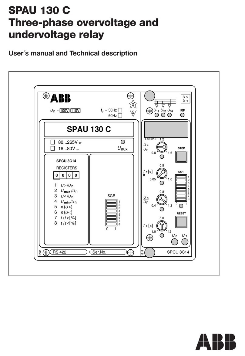
ABB SPAU 140 C Parts list manual

SGB
SGF
SPCU 3D45
PROGRAM
RESET
STEP
o
IRF
I
1
U
1011
2
U
3
U
U
∆
f
∆
ϕ
∆
U
∆
ϕ
∆
f
∆
max
U
n
U
/
min
U
n
U
/
t
n
U
/
VC
SGR
t
CB13
t
CB23
RS 488 Ser.No.
SPAU 140 C
U
aux
REGISTERS OPER.IND.
0000 0
1
2
3
4
5
6
7
8
9
1
2
3
4
5
6
CB13
CB23
2
5
1010B
80...265V ~
–
18...80V –
f
n= 50Hz
60Hz
13
ϕ
∆
23
ϕ
∆
13
f
∆
23
f
∆
3
f
n
U
=100V 110V
1
U
n
U
/
2
U
n
U
/
3
U
n
U
/
NC23
CSF13
CSF23
MODE
NC13
SPCU 3D45
SPAU 140 C
Synchro-check relay
User´s manual and Technical description

2
SPAU 140 C
Synchro-check relay
Contents Features .......................................................................................................................... 3
Application .....................................................................................................................3
Description of operation ................................................................................................. 4
Connection diagram ....................................................................................................... 6
Connections ................................................................................................................... 8
Application example 1 .................................................................................................... 9
Application example 2 .................................................................................................. 10
Intermodular signals ..................................................................................................... 11
Operation indicators ..................................................................................................... 12
Power supply and output relay module ......................................................................... 13
Technical data ............................................................................................................... 13
Commissioning and testing .......................................................................................... 16
Maintenance and repairs ............................................................................................... 18
Exchange and spare parts .............................................................................................. 18
Order numbers ............................................................................................................. 18
Order data .................................................................................................................... 18
Dimensions and instructions for mounting .................................................................. 19
In addition to this general description the following documents are included in the
complete manual:
Synchro-check relay module type SPCU 3D45 1MRS 750195-MUM EN
General characteristics of D-type SPC relay modules 1MRS 750066-MUM EN
1MRS 750315-MUM EN
Issued 96-02-19
Version A
Checked TK
Approved TK
Data subject to change without notice

3
Features Synchro-check relay for checking the conditions
at circuit breaker closing
One synchro-check relay is capable of checking
the close conditions of two separate circuit
breakers.
Synchro-check function for checking synchro-
nism when live lines/busbars are to be connected
together.
Voltage-check function for checking energizing
conditions. Four energizing directions selectable
for each circuit breaker.
Two control modes available: continuous mode
operation for applications where the synchro-
check relay gives the close permission to another
module (e.g. the control module) and command
mode operation for applications where the re-
lay closes the circuit breaker via its own control
output.
Alarm signal for failed CB closing at command
mode operation
Continuous self-supervision of both hardware
and software
Serial port for connecting the relay to the elec-
trical or optical SPA bus
The synchro-check relay SPAU 140 C is an in-
tegrated microprocessor-based voltage measur-
ing relay designed to be used for checking the
conditions for circuit breaker closing. The relay
can be used for closing ring mains, intercon-
necting busbars and connecting generators to
the network.
Application

4
Description of
operation
The relay incorporates two identical stages
which operate as independent units. Both stages
of the synchro-check relay has two parallel func-
tions: a synchro-check function and a voltage-
check function.
The synchro-check relay can be used for two
different operating conditions, the most typical
of which is where both sides of the circuit
breaker to be closed are live. Then synchronism
is always checked before the circuit breaker is
given the permission to close. The other situa-
tion is where one or both sides of the circuit
breaker to be closed are dead and, consequently,
frequency and phase difference cannot be meas-
ured. In this case the relay checks the energiz-
ing direction. The user is able to define the volt-
age range within which the measured voltage is
determined to be "live" and "dead".
The purpose of the synchro-check function is
to find the instant when the voltages on both
sides of the circuit breaker are in synchronism.
The conditions for synchronism are met when
the voltages on both sides of the circuit breaker
have the same frequency, are in phase and are of
such a magnitude that the concerned busbars
or lines can be regarded as live.
When the frequency, phase angle and voltage
conditions are fulfilled, the duration of the syn-
chronizing conditions is checked so as to en-
sure that they will still be met when the con-
tacts of the circuit breaker close. This duration
is determined on the basis of the frequency and
phase difference measured. Depending on the
circuit breaker and the closing system, the de-
lay from the moment the closing signal is given
until the circuit breaker finally closes is about
50 - 250 ms. The CB operate time selected tells
the relay for how long, at least, the conditions
have to persist.
The voltage-check function checks the energiz-
ing direction. Energizing is defined as the situ-
ation where a dead network part is connected
to an energized section of the network. The con-
ditions of the network sections to be controlled
by the circuit breaker, i.e. which side has to be
live and which side dead, are determined by set-
ting. A situation where both sides are dead is
possible as well.
When the energizing direction corresponds to
the settings, the situation has to be constant for
a certain time before the close signal is permit-
ted. The purpose of this operate time (dead time)
is to make sure that the dead side remains
deenergized and that the situation is not due to
a temporary interference. Should the conditions
not persist for the specified operate time, the
operate time is reset and the procedure is started
again when allowed by the conditions. Not un-
til the required energizing situation has been
constant throughout the set operate time, cir-
cuit-breaker closing is permitted.

5
U1
U2
U3
Blocking input
BS13
Blocking input
BS23
Closing command
signal CS13
Closing command
signal CS23
Closing signal
CB13
Closing signal
CB23
Alarm
IRF
Serial communication I/O
Voltage-check function
Serial communication
Continuous/ Command
mode operation
25
Synchro-check
funktion
Two identical operation
stages
Fig. 1. Supervision functions of synchro-check relay SPAU 140 C. The encircled numbers refer to
the ANSI number of the concerned function. (ANSI = American National Standards Institute)

6
U1
U3
I/O
Rx Tx
Uaux
I
I
I
L1
L2
L3
L3
L2
L1
I
62 61 70 71 72
IRF
13
63 14 15 16 17 18 19 20 21 10 11 2322 47 4845 46 85 86 87 88 68 69
SGB/1
SGB/2
ALARM
SGR/1
SGR/5
SGR/7
1
IRF
A
B
CD
CB13
CB23
NC13
CSF13
NC23
CSF23
T1
T2
T3
T4
T5
T6
1
SGR/3
BS13
CS13
BS23
CS23
SGB/4
SGB/3
BS13 BS23 CB13 CB23
U3
U2
SPA-ZC_
X1
X2
X3
SC13
VC13
SC23
VC23
SPAU 140 C
100V
110V 100V 100V
110V 110V
CS13 CS23
SERIAL
PORT
U1 U2 U3
Connection
diagram
Fig. 2. Complete connection diagram for the synchro-check relay SPAU 140 C. The switches for
configuring the control signals of the output relays and the external blocking/control inputs are
illustrated in the diagram.

7
Rx
Tx
22
23
45
46
47
48
Made in Finland
13
14
15
16
17
18
19
20
21
10
11
61
62
63
85
86
87
88
70
71
72
68
69
= 63
Fig. 3. Rear view of synchro-check relay SPAU 140 C
Uaux Auxiliary voltage
A,B,C,D Output relays
IRF Self-supervision
SGB Switchgroup for the configuration of blocking and command signals
SGR Switchgroup for the configuration of alarm signals
CB13 Circuit breaker close permission/close command, stage 1
CB23 Circuit breaker close permission/close command, stage 2
ALARM Signal output
BS13 Blocking signal for stage 1
BS23 Blocking signal for stage 2
CS13 Control signal, request for CB closing, stage 1
CS23 Control signal, request for CB closing, stage 2
X1 Synchro-check relay module SPCU 3D45
X2 Power supply and output relay module SPTU 240 R4 or SPTU 48 R4
X3 Input module SPTE 3E10
T1...T6 Operation indicators 1...6
SERIAL PORT Serial port for serial communication
SPA-ZC Bus connection module
Rx Tx Receiver (Rx) and transmitter (Tx) for the connection of optical fibres

8
Connections Terminal Function
13-14 Measured voltage U1, rated voltage 100 V
13-15 Measured voltage U1, rated voltage 110 V
16-17 Measured voltage U2, rated voltage 100 V
16-18 Measured voltage U2, rated voltage 110 V
19-20 Measured voltage U3, rated voltage 100 V
19-21 Measured voltage U3, rated voltage 110 V
The relay is able to measure either phase-to-phase voltages or phase-to-neutral
voltages, but phase-to-phase voltages are preferred.
10-11 Stage 1 of the synchro-check relay can be blocked by applying an external auxiliary
voltage level blocking signal BS to terminals 10-11. The blocking function is se-
lected with switch 1 of switchgroup SGB in the main menu of the relay. The
blocking function is not activated in the default setting of the relay.
22-23 Stage 2 of the synchro-check relay can be blocked by applying an external auxiliary
voltage level blocking signal BS to terminals 22-23. The blocking function is se-
lected with switch 2 of switchgroup SGB in the main menu of the relay. The
blocking function is not activated in the default setting of the relay.
45-46 When command mode operation has been selected for stage 1, the stage is acti-
vated for CB closing by an auxiliary voltage level control signal CS13, applied to
the terminals 45-46. If continuous mode operation has been selected no control
signal need be applied to the relay. Switch 3 of switchgroup SGB is used for select-
ing the desired mode of operation. Default setting of stage 1: continuous mode
operation.
47-48 When command mode operation has been selected for stage 2, the stage is acti-
vated for CB closing by an auxiliary voltage level control signal CS23, applied to
the terminals 47-48. If continuous mode operation has been selected no control
signal need be applied to the relay. Switch 4 of switchgroup SGB is used for select-
ing the desired mode of operation. Default setting of stage 2: continuous mode
operation.
68-69 At command mode operation the alarm signal for failed circuit breaker closing
(NC13 and NC23) and for CB close request signals that have remained activated
(CSF13 and CSF23) is received via output relay A at command mode operation.
The switches 1, 3, 5 and 7 of switchgroup SGR are used for the configuration of
the alarm signals. No alarm signals are received at continuous mode operation.
87-88 Output relay B provides the permission signal for CB closing via stage 2 of the
synchro-check relay module.
85-86 Output relay C provides the permission signal for CB closing via stage 1 of the
synchro-check relay module.
70-71-72 Output relay D, terminals 70-71-72, operates as the output relay of the self-super-
vision system of the synchro-check relay. Normally, the relay operates on the closed-
circuit principle and the contact gap 70-72 is closed. If the self-supervision system
detects a permanent fault or the voltage supply to the relay fails, the output relay D
provides an alarm signal by closing the normally open contact gap 71-72.
61-62 The auxiliary supply voltage of the synchro-check relay is connected to terminals
61-62. At DC supply voltage the positive lead is connected to terminal 61. The
permitted voltage range of the power supply and output relay module fitted in the
relay module is indicated on the front panel of the relay. Further technical details
about the auxiliary voltage supply system is given in the section "Power supply and
output relay module".
The synchro-check relay is connected to the data
communication bus and, further, to a control
data communicator, e.g. SACO 148D4, via the
9-pole, D-type subminiature connector located
on the rear of the relay and a bus connection
module type SPA-ZC17_, or SPA-ZC21_ .
9
Application
example 1
The network and the generator running in par-
allel with the network are connected together
through the line AB. When a fault occurs be-
tween A and B the relay protection opens the
circuit breakers A and B, thus isolating the faulty
section from the network and making the arc
that caused the fault extinguish. The first at-
tempt to recover is a delayed auto-reclosure
made a few seconds later. Then the auto-reclose
relay gives a command signal to the synchro-
check relay to close the circuit breaker A. The
synchro-check relay SPAU 140 C performs a
voltage check, as the line AB is deenergized
(U1>Umax, U3< Umin). After verifying that the
line AB is dead and that the energizing direc-
tion is correct, the relay energizes the line (U1 -
> U3) by closing circuit breaker A. Then the
PLC of the power plant discovers that the line
has been energized and sends a signal to the
other synchro-check relay to close circuit breaker
B. Since both sides of circuit breaker B are live
(U1 > Umax, U3 > Umax), the synchro-check
relay controlling circuit breaker B performs a
synchro-check and, if the network and the gen-
erator are in synchronism, closes the circuit
breaker.
AB
SPAU 140 C
PLC
SPAU 140 C
Auto-reclosure
relay
U1 U3 U1U3
Fig. 4. Synchro-check relay SPAU 140 C checking energizing conditions and synchronism.

10
Application
example 2
Synchronism check
between busbar and
line
Fig. 5. Synchro-check relay SPAU 140 C used for checking synchronism between busbar and line
In the application illustrated in Fig. 5 stage 1 of
the synchro-check relay is used for checking the
synchronism between the busbar and the line.
Stage 2 is inactive (SGF/7 = 0 and SGF/8 = 0).
Both the synchro-check function and the volt-
age-check function of stage 1 are operational
(SGF/3 = 1 and SGF/4 = 1).
Command mode operation has been selected
for stage 1 (SGB/3 = 1), which means that press-
ing a push-button activates a request signal for
the synchro-check relay to close the circuit
breaker. This request signal should be active
throughout the specified checking time. The
permission for the relay to operate is given over
this request input, and once the conditions for
CB closing are met, the synchro-check relay de-
livers a close signal to the circuit breaker via out-
put contact C. Should the attempt to close the
circuit breaker fail (SGR/1 =1), that is, the cir-
cuit breaker is not closed within the preset time,
an alarm signal will be received through con-
tact A.
A blocking voltage applied to the blocking in-
put BS13 (SGB/1=1) over the auxiliary contact
of the miniature circuit breaker prevents the
synchro-check relay from performing the volt-
age-check function when the miniature circuit
breaker trips. It is very important that the volt-
age-check function is prevented by the tripping
of the m.c.b. Unless a blocking signal has been
provided, the synchro-check relay measures the
voltage over this input to be zero and, should
the energizing conditions then correspond to
the setting concerned (SGF/1 and SGF/2), it
gives a close signal to the circuit breaker, when
the command input (push-button depressed) is
active.
U1
U3
I/O
Rx Tx
Uaux
I
L3
L2
L1
I
62 61 70 71 72
IRF
13
63 14 1516 17 18 19 20 21 10 11 2322 47 4845 46 85 86 87 88 68 69
SGB/1
SGB/2
ALARM
SGR/1
SGR/5
SGR/7
1
IRF
A
B
CD
CB13
CB23
NC13
CSF13
NC23
CSF23
T1
T2
T3
T4
T5
T6
1
SGR/3
BS13
CS13
BS23
CS23
SGB/4
SGB/3
BS13 BS23 CB13 CB23
U3
U2
SPA-ZC_
X1
X2
X3
SC13
VC13
SC23
VC23
SPAU 140 C
100V
110V 100V 100V
110V 110V
CS13 CS23
SERIAL
PORT
U1 U2 U3

11
Intermodular
control signals
The figure below illustrates the configuration
of the blocking and control signals (SGB) and
alarm signals (SGR), and the selection of the
check functions (SGF) of the stages.
>1
CB13
CB23
ALARM
U1
U3
U
2
BS23
CS23
CS13
BS13
SGR/5
SGR/7
SGR/1
SGR/3
CSF13
NC13
SGB/3
SGB/1
NC23
CSF23
SGB/4
SGB/2
IR
F
D
C
A
B
SPCU 3D45 SPTU __ R
4
SC13
VC13
SC23
VC23
>1
>1
SGF/3
SGF/4
SGF/7
SGF/8
II
I
CS23
BS23
U3
U2
CS13
BS13
U1
U3
SGF/1
SGF/2
SGF/5
SGF/6
Fig. 6. Control signals between the modules of the synchro-check relay SPAU 140 C and the
configuration switches.
U1,U2,U3 Measured voltages
CB13 Close permission/close command, stage 1
CB23 Close permission/close command, stage 2
ALARM Alarm signal from stages 1 and 2
BS13 External blocking signal to stage 1
BS23 External blocking signal to stage 2
CS13 External control signal to stage 1, request for CB closing
CS23 External command signal to stage 2, request for CB closing
IRF Signal for internal relay fault
SGF Switchgroup for configuring the functions of the synchro-check relay
SGB Switchgroup for configuring the blocking and command functions
SGR Switchgroup for configuring the alarm functions

12
SGB
SGF
SPCU 3D45
PROGRAM
RESET
STEP
o
IRF
I
1
U
1011
2
U
3
U
U
∆
f
∆
ϕ
∆
U
∆
ϕ
∆
f
∆
max
U
n
U
/
min
U
n
U
/
t
n
U
/
VC
SGR
t
CB13
t
CB23
RS 488 Ser.No.
SPAU 140 C
U
aux
REGISTERS OPER.IND.
0000 0
1
2
3
4
5
6
7
8
9
1
2
3
4
5
6
CB13
CB23
2
5
1010B
80...265V ~
–
18...80V –
f
n= 50Hz
60Hz
13
ϕ
∆
23
ϕ
∆
13
f
∆
23
f
∆
3
f
n
U
=100V 110V
1
U
n
U
/
2
U
n
U
/
3
U
n
U
/
NC23
CSF13
CSF23
MODE
NC13
SPCU 3D45
Operation
indicators
The yellow operation indicator is lit as soon as
one of the stages of the relay operates and has
activated its control output. When the stage re-
sets, the yellow LED is reset as well.
Operation Explanation
indicator
1 CB13 Close signal of stage 1 is active
2 CB23 Close signal of stage 2 is active
3 NC13 Stage 1 failed to close the CB (only command mode operation)
4 NC23 Stage 2 failed to close the CB (only command mode operation)
5 CSF13 Signal CS13 requesting CB closing is active too long
(only command mode operation)
6 CSF23 Signal CS23 requesting CB closing is active too long
(only command mode operation)
The IRF LED indicates internal relay fault. The
indicator is lit about 1 minute after the self-su-
pervision system has detected a permanent fault.
At the same time as the LED goes on the relay
module delivers a control signal to the output
relay of the self-supervision system. In most cases
a fault code that shows the nature of the fault
appears on the display of the relay module. This
fault code that consists of a red digit 1 and a
green code number cannot be reset from the
display. The code should be recorded to facili-
tate service.
The leftmost red digit on the display has two
functions: on one hand, it serves as address in-
dicator for different types of data and, on the
other hand, as operation indicator of the two
stages of the synchro-check relay. Operation is
indicated by a red digit, 1 or 2, depending on
which of the stages that activated its close sig-
nal.
The red digits 3, 4, 5 and 6 indicate an abnor-
mal situation at command mode operation.
These alarm indicators remain lit even when the
situation returns to normal, and have to be re-
set by pressing the reset push-button. A non-
reset operation indicator does not affect the
operation of the relay module, which is always
alert. The following table, which is printed on
the relay's front plate under the name OPER.
IND., explains the code numbers of the opera-
tion indicators.

13
Power supply
and output relay
module
The combined power supply and I/O relay
module is located behind the relay's system
panel. The module incorporates the power sup-
ply unit, the output relays with control circuits,
and the electronic circuits of the external con-
trol input. The power supply and output relay
module can be withdrawn after removal of the
system panel of the relay.
The power supply module is a transformer con-
nected, i.e. galvanically isolated primary and
secondary side, flyback-type DC/DC converter.
The primary side of the module is protected
with a fuse, F1, located on the PCB of the mod-
ule. The fuse size is 1 A (slow).
A green LED indicator Uaux on the system panel
is lit when the power supply module is in op-
eration.
The combined power supply and I/O modules
are available in two versions with different in-
put voltage ranges:
SPTU 240R4 Uaux = 80...265 V dc/ac
SPTU 48R4 Uaux = 18...80 V dc
The system panel of the relay indicates the volt-
age range of the power supply module of the
relay assembly.
Technical data Energizing inputs 100 V 110 V
Energizing inputs 13-14, 16-17, 19-20 13-15, 16-18, 19-21
Rated voltage 100 V 110 V
Continuous voltage withstand 2.0 x Un
Burden at rated voltage <0.5 VA
Rated frequency 50 Hz / 60 Hz
Permissible frequency range 45...65 Hz
Output contacts
Terminals 85-86, 87-88
- rated voltage 250 V ac/dc
- carry continuously 5 A
- make and carry for 0.5 s 30 A
- make and carry for 3.0 s 15 A
- breaking capacity for dc, when the
control circuit time-constant L/R<40 ms
at 48/110/220 V dc control circuit voltage 5 A/3 A/1 A
Contact material AgCdO2
Signal contacts
Terminals 70-71-72
68-69
- rated voltage 250 V ac/dc
- carry continuously 5 A
- make and carry for 0.5 s 10 A
- make and carry for 3.0 s 8 A
- breaking capacity for dc, when the
control circuit time-constant L/R <40 ms
at 48/110/220 V dc control circuit voltage 1 A/0.25 A/0.15 A
Contact material AgCdO2
External control inputs
Terminals 10-11, 22-23, 45-46, 47-48
External control voltage level 18...265 V dc or 80...265 V ac
Typical control current of input circuit 2...20 mA
Power supply and output relay module
Module, type SPTU 240 R4 80...265 V dc/ac
Module, type SPTU 48 R4 18...80 V dc
Power consumption under quiescent/
operating conditions about 5 W/7 W

14
Synchro-check relay module SPCU 3D45
Synchro-check function
Upper voltage level threshold Umax
Setting range 0.5...1.0 x Un
Voltage difference ∆U
Setting range 0.02...0.4 x Un
Frequency difference ∆f
Setting range 0.02...0.5 Hz
Phase difference ∆ϕ 5...50°
Operate time when the voltage on the
energizing input rises from 0 to 1.0 x Un160 ms ±20 ms (fixed)
Operate time tCB13 of CB controlled
by stage 1 0.05...0.25 s
Operate time tCB23 of CB controlled
by stage 2 0.05...0.25 s
Voltage-check function
Upper voltage level threshold Umax
(the same as for the synchro-check function)
Setting range 0.5...1.0 x Un
Lower voltage level threshold Umin
Setting range 0.1...0.8 x Un
Energizing direction
Selectable energizing directions
for stage 1 - both dead or U1 –> U3 or U1 <– U3
- U1 <– U3
- U1 –> U3
- U1 <– U3 or U1 –> U3
Selectable energizing directions
for stage 2 - both dead or U2 –> U3 or U2 <– U3
- U2 <– U3
- U2 –> U3
- U2 <– U3 or U2 –> U3
Operate time delay tvc (dead time)
- setting range 0.1...20 s
- setting accuracy 0.01 s

15
Mode of operation
Command mode or continuous mode operation
Command mode operation
Max. close signal length tPULSE at
command mode operation
Setting range 0.2...20 s
Time permitted for checking and request
for CB closing tCHECK
Setting range 0.05...300 s
Data transmission
Transmission mode Fibre-optic serial bus
Data code ASCII
Data transfer rates 4800 Bd or 9600 Bd
Bus connection module without external supply
- for plastic core cables SPA-ZC 21 BB
- for glass fibre cables SPA-ZC 21 MM
Bus connection module with external supply
- for plastic core cables SPA-ZC 17 BB
- for glass fibre cables SPA-ZC 17 MM
Test voltages
Insulation test voltage, inputs and outputs
between themselves and to the relay frame as
per IEC 255-5 and SS 436 15 03 2 kV, 50 Hz, 1 min
Impulse test voltage, inputs and outputs
between themselves and to the relay frame as
per IEC 255-5 and SS 436 15 03 5 kV, 1.2/50 µs, 0.5 J
Insulation resistance as per IEC 255-5 100 MΩ, 500 V dc
Disturbance tests
High frequency interference test voltage,
inputs and outputs between themselves
and to the relay frame as per IEC 255-22-1
and SS 436 15 03 2.5 kV, 1 MHz
Fast transients as per IEC 255-22-4 Class III, 2 kV
Electrostatic discharge test as per IEC 255-22-2 8 kV, 150 pF
Environmental conditions
Specified ambient service temperature range -10...+55°C
Temperature influence on the operation values
of the relay over the specified ambient service
temperature range <0.1%/°C
Long term damp heat withstand according
to IEC 68-2-3 <95% at 40°C, 96 h
Transport and storage temperature range -40...+70°C
Degree of protection by enclosure of relay case
according to IEC 529 at panel mounting IP54
Weight of relay about 3.0 kg

16
Commissioning
and testing
The relay incorporates a self-supervision logic
that continuously supervises the operation of
the relay and provides an IRF alarm when an
internal relay fault is detected. However, the
manufacturer recommends regular testing of the
relay, for instance, every five years. This test
should be carried out as a primary test, which
includes the entire supervision chain covered by
the synchro-check relay, from the instrument
transformers to the circuit breakers.
Special attention should be paid to the connec-
tion of the relay. Further, it should be checked
that the primary side wiring is correct. The ta-
ble below can be used for checking the wiring.
Measuring circuit
wiring and wiring
test
Faulty wiring of the voltage inputs of the relay
will cause malfunction in the synchro-check re-
lay. If the wires of an energizing input have
changed places, the polarity of the voltage of
the input is reversed (180°). Then the relay per-
mits circuit breaker closing in a situation where
the voltages actually are in opposite phases. For
this reason it is extremely important that the
wiring from the voltage transformers to the ter-
minals on the rear of the relay is consistent re-
garding the energizing inputs U1, U2 and U3.
The table below shows the energizing inputs and
the related terminals.
Energizing input U1/100 V Energizing input U2/100 V Energizing input U3/100 V
Terminal 13 16 19
14 17 20
Energizing input U1/110 V Energizing input U2/110 V Energizing input U3/110 V
Terminal 13 16 19
15 18 21
The wiring should be verified by checking the
reading of the phase difference measured be-
tween the voltages U1 and U3 and between the
voltages U2 and U3. When checking the phase
differences the circuit breaker between the con-
cerned voltages have to be closed, to make sure
there is no phase difference. The phase differ-
ence measured by the relay has to be close to
zero within the permitted accuracy tolerances.
The phase differences measured are indicated
in the third submenu of the LEDs U1 and U2.
At the same time it is recommended to check
the voltage difference and the frequency differ-
ences presented in the first and the second sub-
menu, respectively. These values should be
within the permitted tolerances, close to zero.
The frequency measured from the network, for
example 50 Hz, can be read in the first sub-
menu of the U3 indicator.

17
Miniature circuit-
breakers of the
voltage measuring
circuits
Supervision of the condition of the relay's ex-
ternal measuring circuit is not incorporated in
the synchro-check relay. Should the external
measuring circuit of some reason be damaged,
malfunction may follow, and based on the volt-
age measured, the relay then considers the line/
busbar to be dead, although it actually is ener-
gized. In consequence, a voltage-check is made,
and, if the energizing direction corresponds to
the relay setting, a close permission/command
is given. Then the close operation is made
against a live section without the synchronism
being checked, as the energizing conditions were
considered to be fulfilled. For this reason it is
important that the safety switch of the measur-
ing circuit, when operating, provides the
synchro-check relay with a blocking signal that
prevents circuit breaker closing. When the re-
lay is commissioned, it should be checked that
the blocking function operates correctly and that
the configuration of the blocking signals (SGB
switchgroup) is in order. The states of the indi-
vidual blocking signals can be checked in the
first submenu of register 0.
The miniature circuit-breakers of the measur-
ing circuit and the blocking function can be
tested as follows.
- Enable blocking of the stages by selecting the
checksum 3 for the switchgroup SGB. Then
stage 1 is blocked by the signal BS13 and stage
2 by the signal BS23.
- Configure switchgroup SGF so that the check-
sum is 136. Then the stages operate when the
operate time tvc expires. Stage 1 activates the
output signal CB13 and stage 2 the output
signal CB23. The blocking function should
operate so that an activated output signal re-
sets, when the blocking input of the stage is
activated; the blocking signal BS13 resets the
output CB13 and the blocking signal BS23
resets the output CB23. When the blocking
has been eliminated, the output returns to its
active state.
Alternatively, the test can be carried out so that
switchgroup SGB is given the checksum value
3 and switchgroup SGF the checksum value 0
and then the blocking signals to the stages are
activated. The next step is to give switchgroup
SGF the checksum value 136, which enables
the voltage-check function of both stages. After
the setting value has been changed the output
signal of neither stage is allowed to activate. Fi-
nally, the blocking of the stages is eliminated
and then the output signal has to be activated
when the preset operate time expires.

18
Maintenance
and repairs
When the synchro-check relay is used under the
conditions specified in "Technical data", it re-
quires practically no maintenance. The relay
includes no parts or components that are sensi-
tive to physical or electrical wear under normal
operating conditions.
Should the temperature and humidity at the
operating site differ from the values specified,
or the atmosphere contain chemically active
gases or dust, the relay should be visually in-
spected in association with the secondary test-
ing of the relay. This visual inspection should
focus on:
- Signs of mechanical damage to relay case and
terminals
- Collection of dust inside the relay case; remove
with compressed air
- Signs of corrosion on terminals, case or inside
the relay
If the relay malfunctions or the operating val-
ues differ from those specified, the relay should
be overhauled. Minor measures such as change
of a plug-in-type PC board can be taken by
normal service personnel with the required skill.
In uncertain cases and if the fault is permanent
the manufacturer or his nearest representative
should be contacted for further information
about checking, overhaul and recalibration of
the relay.
Note!
The protection relay contains circuits that are
sensitive to electrostatic discharge. If you have
to withdraw a relay module, ensure that you are
at the same potential as the module, for instance,
by touching the case.
Note!
Static protective relays are measuring instru-
ments and should be handled with care and pro-
tected against moisture and mechanical stress,
especially during transport.
Exchange and
spare parts
Synchro-check relay module SPCU 3D45 RS 426 005 -AA
Power and output relay module
- Uaux = 80...265 V ac/dc SPTU 240 R4 RS 941 024 -AA
- Uaux = 18...80 V dc SPTU 48 R4 RS 941 024 -BA
Relay case including I/O module SPTK 3E10
I/O module, as a separate unit SPTE 3E10
Bus connection module SPA-ZC 17_
Bus connection module SPA-ZC 21_
Order numbers Synchro-check relay without test adapter
SPAU 140 C RS 488 001 -AA, CA, DA, FA
Synchro-check relay with test adapter RTXP 18
SPAU 140 C RS 488 201 -AA, CA, DA, FA
The last two letters indicate the rated frequency fnand the auxiliary voltage Uaux
of the relay as follows:
AA: fn= 50 Hz and Uaux = 80...265 V ac/dc
CA: fn= 50 Hz and Uaux = 18...80 V dc
DA: fn= 60 Hz and Uaux = 80...265 V ac/dc
FA: fn= 60 Hz and Uaux = 18...80 V dc
Order data Type Example
1. Quantity 15 relays SPAU 140 C
2. Order number RS 488 001 - AA
3. Rated frequency fn= 50 Hz
4. Auxiliary voltage Uaux = 110 V dc
5. Accessories 15 connection modules SPA-ZC 21 MM
30 fibre-optic cables SPA-ZF MM 100
6. Special requirements –

19
Dimensions and
instructions for
mounting
The basic model of the protection relay case is
designed for flush-mounting. When required,
the mounting depth of the case can be reduced
by means of raising frames: type SPA-ZX 111
reduces the depth by 40 mm, type SPA-ZX 112
by 80 mm and type SPA-ZX 113 by 120 mm.
The type designation of the case for surface
mounting is SPA-ZC 117.
Raising frame
SPA-ZX 111
SPA-ZX 112
SPA-ZX 113
176
136
96
74
114
154
ab
ab
Panel cut-out
129 ±1
139 ±1
142
162
136
30 34
250
186
216
Fig. 7. Dimension and mounting drawings for synchro-check relay SPAU 140 C.
The relay case is made of anodized profile alu-
minium and finished in beige.
The rubber gasket fitted to the mounting collar
provides an IP 54 degree of protection by en-
closure between the relay case and the mount-
ing base.
The hinged cover of the case is made of trans-
parent, UV-stabilized polycarbonate polymer
and provided with a sealable locking screw. The
rubber gasket of the cover provides an IP 54
degree of protection between the case and the
cover.
The required input and output wires are con-
nected to the screw terminals on the rear panel.
Each terminal screw is dimensioned for one wire
of maximum 6 mm2or two wires of maximum
2.5 mm2. Part of the control inputs is located
in the detachable six-pole terminal block. The
9-pole D-type connector is intended for serial
communication.

Table of contents
Other ABB Relay manuals

ABB
ABB KD-10 Manual

ABB
ABB REU 610 Product manual

ABB
ABB RELION 650 SERIES User manual

ABB
ABB REL650 series Instructions for use

ABB
ABB A135-H65 User manual

ABB
ABB KLF Series Manual

ABB
ABB EF19 User manual

ABB
ABB Relion 615 series User manual

ABB
ABB Relion 611 Series Instructions for use

ABB
ABB RXPDK 21H User instructions