ABB SPAF 140 C Parts list manual

SPCF 1D15
TRIP
RESET
STEP
0024C
PROGRAM
IRF
f
U
f
<
>
<
>
d
f
d
t
SGR
SGB
SGF
[ ]
n
f
U
/
<
Hz
n
U
[ ]
f
Hz
∆
[ ]
r
t
s
[ ]
d
f
d
t
/ /
Hz s
[ ]
1
f
Hz
[ ]
4
f
Hz
[ ]
3
f
Hz
[ ]
2
f
Hz
[ ]
1
t
s
,1
t
,
[ ]
2
t
s
,2
t
,
[ ]
3
t
s
,3
t
,
[ ]
4
t
s
,4
t
,
U
RS 452 001 - Ser.No.
SPAF 140 C
aux
REGISTERS OPER.IND.
1
2
3
4
5
6
Stage 1 Start
Stage 1 Trip
0476A
80...265V ~
–
18...80V –
Stage no.
Start ctr
U
n
U
/
f[Hz] [Hz/s]
Stage 2 Trip
Stage 3 Start
Stage 3 Trip
Stage 2 Start
SPCF 1D15
2
5
1
2
3
4
5
6
Stage 4 Start
Stage 4 Trip
Rec. Due
Rec. Over
A
7
8
9
max
min
f
max
min
df/dt
df/dt
n
U
=100V/110V/115V/120V
0000 0
SPAF 140 C
Frequency Relay
User´s manual and Technical description

2
SPAF 140 C
Frequency Relay
Contents Features .......................................................................................................................... 2
Application .....................................................................................................................3
Description of operation ................................................................................................. 3
Connections ................................................................................................................... 4
Specification of input and output terminals.................................................................... 5
Operation indicators ....................................................................................................... 6
Combined power supply and I/O module ...................................................................... 6
Technical data (modified 2001-04) .................................................................................. 7
Example of application ................................................................................................... 9
Testing .......................................................................................................................... 11
Maintenance and repair ................................................................................................ 12
Spare parts .................................................................................................................... 12
Order numbers (modified 1998-03) .............................................................................. 12
Dimension drawings and mounting.............................................................................. 13
Ordering information ................................................................................................... 13
In addition to the general part, the complete manual of the frequency relay SPAF 140 C
includes the following relay module descriptions:
Combined frequency and rate of change of frequency relay module 1MRS 750583-MUM EN
General characteristics of D type relay modules 1MRS 750066-MUM EN
Features Single-phase four-stage combined overfre-
quency/underfrequency relay
Each protection stage includes a frequency rate
of change function (df/dt), which can be used
alone or in combination with the overfrequency/
underfrequency function.
Each protection stage includes two separate
adjustable timers
Recovery function
Programmable undervoltage blocking
Four rated voltages, to be selected in the soft-
ware
Adjustable rated frequency
Four external control inputs enabling separate
blocking of each stage, etc.
Two freely configurable heavy-duty output re-
lays, one signal relay and one self-supervision
output relay
Recording of measured data, which can be used
for analysing the network condition.
Transfer of data over serial communication bus
Continuous self-supervision with internal fault
diagnosis
Reading and writing of setting values via dis-
play and front panel push-buttons, a PC with
setting software or from higher system levels over
the serial bus.
1MRS 750135-MUM EN
Issued 1997-02-05
Modified 2002-04-12
Version C
Checked MK
Approved OL
Data subject to change without notice

3
Application The frequency relay SPAF 140 C is designed to
be used for the overfrequency/underfrequency
protection of generators, motors and other ac
equipment. For instance, even a small devia-
tion from the rated frequency may cause me-
chanical damage to a generator set.
In addition, the frequency relay SPAF 140 C
can be used for monitoring the power balance
in the network and disconnecting parts of the
network in a situation of power deficiency.
The frequency relay SPAF 140 C is a secondary
relay, which is connected to the voltage trans-
formers of the network section to be protected.
The relay incorporates one relay module: the
combined frequency and rate of change of fre-
quency module type SPCF 1D15.
The relay module includes four protection
stages, each of which with its own frequency
function (f), its own rate of change of frequency
function (df/dt) and two adjustable operate
times (t and t’).
When the frequency limit of a stage is set below
the rated frequency, the protection stage oper-
ates as an underfrequency stage. Correspond-
ingly, the stage has the function of an over-
frequency stage, when the frequency level is set
above the rated frequency. The frequency set-
ting cannot be the same as the rated frequency.
The operation of the df/dt function of a pro-
tection stage is based on the same principle as
the frequency function, which means that if a
protection stage operates as an underfrequency
stage, the sign of the df/dt function is negative.
Then the df/dt function starts once the abso-
lute value of the rate of frequency drop exceeds
the df/dt limit. When required, the frequency
function and the df/dt function can be com-
bined so that the criteria for operation of both
functions have to be fulfilled at the same time.
Once a preset condition is fulfilled, the stage
starts and, at the same time, it activates a tim-
ing circuit. No start signal can be programmed
for the output relays. When the stage times out,
the relay produces a trip signal. The trip signal
can be linked to the desired output relay.
Description of
operation

4
Connections
IRF
SS1
TS1
SS2
TS2
SS3
TS3
SS4
TS4
I/O
BS1
BS2
BS3
BS4
BS5
U1
4
f
4
df/dt
48 47 46 45 23 22 11 10
BS4 BS3 BS2 BS1
X0 63 13 1416 62 61
U
aux
+-
=
~_
+ (~)
- (~)
70 71 72 68 69 85 86 87 88
IRF SS1 TS1 TS2 SERIAL
PORT
(SPA)
+ + +
SPA-ZC_
Rx Tx
U3
+
U2
100 V
Not
Used
a
n
d
d
N
A
+
01
-
-
+
0
+
1
Fig. 1. Connection diagram for frequency relay SPAF 140 C
Uaux Auxiliary voltage
TS1, TS2 Output relays (heavy-duty)
SS1 Output relay
IRF Self-supervision output relay
BS1...BS4 Control signals
U1 Combined frequency and rate of change of frequency relay module
SERIAL PORT Serial communication port
SPA-ZC_ Bus connection module
Rx/Tx Fibre-optic cable connection

5
Rx
Tx
22
23
45
46
47
48
Made in Finland
13
14
15
16
17
18
19
20
21
10
11
61
62
63
85
86
87
88
70
71
72
68
69
= 63
Fig. 2. Terminals of frequency relay SPAF 140 C
Specification of
input and output
terminals
Terminal interval Function
13-14 Phase-to-phase voltage U12 100 V
13-15 Not in use
16-17 Not in use
16-18 Not in use
19-20 Not in use
19-21 Not in use
10-11 External blocking signal BS1
22-23 External blocking signal BS2
45-46 External blocking signal BS3
47-48 External blocking signal BS4
68-69 Output relay SS1
85-86 Output relay TS1
87-88 Output relay TS2
70-71-72 Output relay IRF
61-62 Auxiliary voltage supply.
The positive pole of the DC supply is connected to terminal 61.
The auxiliary voltage is marked on the front plate.
The protection relay connects to the fibre-op-
tic data bus via the bus connection module SPA-
ZC 17 or SPA-ZC 21 to be fitted to the D con-
nector on the rear panel of the relay. The opti-
cal fibres are connected to the counter contacts
Rx and Tx of the module. The selector switches
of the bus connection module should be in the
position "SPA".

6
Operation
indicators
SPCF 1D15
TRIP
RESET
STEP
0024C
PROGRAM
IRF
f
U
f
<
>
<
>
d
f
d
t
SGR
SGB
SGF
[ ]
n
f
U
/
<
Hz
n
U
[ ]
f
Hz
∆
[ ]
r
t
s
>
[ ]
d
f
d
t
/ /
Hz s
[ ]
1
f
Hz
[ ]
4
f
Hz
[ ]
3
f
Hz
[ ]
2
f
Hz
[ ]
1
t
s
,1
t
,
[ ]
2
t
s
,2
t
,
[ ]
3
t
s
,3
t
,
[ ]
4
t
s
,4
t
,
U
RS 452 001 - Ser.No.
SPAF 140 C
aux
REGISTERS OPER.IND.
1
2
3
4
5
6
Stage 1 Start
Stage 1 Trip
0476A
80...265V ~
–
18...80V –
Stage no.
Start ctr
U
n
U
/
f[Hz] [Hz/s]
Stage 2 Trip
Stage 3 Start
Stage 3 Trip
Stage 2 Start
SPCF 1D15
2
5
1
2
3
4
5
6
Stage 4 Start
Stage 4 Trip
Rec. Due
Rec. Over
A
7
8
9
max
min
f
max
min
df/dt
df/dt
n
U
=100V/110V/115V/120V
0000 0
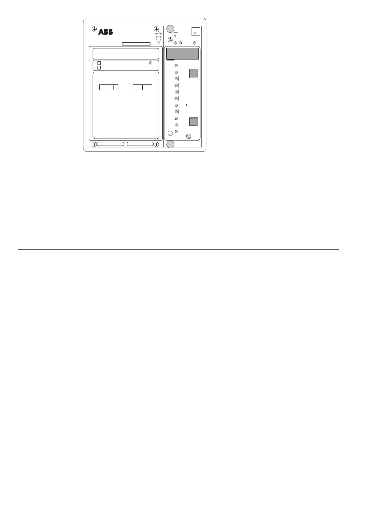
modules and on the system panel of the fre-
quency relay.
Start indications can be programmed to re-
main lit, even though the stage resets. In gen-
eral, the numbers indicating start are auto-
matically reset, whereas trip codes have to be
manually reset by pressing the RESET push-
button. The TRIP indicator at the bottom
part of the front panel can be set to indicate
tripping of any stage. The BS_ signals can be
configured to automatically reset the trip
indicators. A non-reset operation indicator
does not affect the operation of the relay
module.
3. A measured or set value presented on the dis-
play is identified by yellow LEDs on the front
panel.
4. A permanent fault detected by the self-
supervision system is indicated by the IRF
indicator of the concerned relay module
and a fault code on the display of the relay
module. The fault code should be recorded
to facilitate maintenance and repair.
The operation indicators are described in more
detail in the descriptions of the relay modules.
Fig. 3. Front panel of frequency relay SPAF 140 C
1. The green LED indicator Uaux on the sys-
tem panel is lit when the power supply is
operating.
2. Measured values, settings and start and trip
data are indicated on the display. Starting and
tripping are indicated by a red operation code
to the left of the display. The operation codes
are explained in the descriptions of the relay
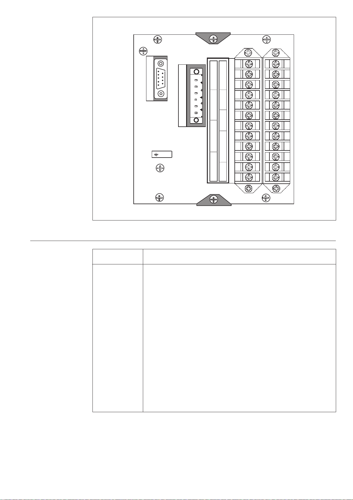
Combined power
supply and I/O
module
The power supply and I/O module of the fre-
quency relay SPAF 140 C is located behind the
system panel of the relay. The module can be
withdrawn after removal of the system panel.
The power supply and I/O module includes the
power supply unit, the output relays with con-
trol circuits and the electronic circuits of the
external control inputs.
The power supply module is a transformer-con-
nected, i.e. galvanically isolated primary and
secondary circuits, flyback type DC converter.
The primary side is protected with a fuse, F1,
situated on the PC board of the module. The
fuse size is 1 A (slow).
The green LED indicator Uaux on the front
panel is lit when the power supply unit is in
operation. The supervision of the voltages sup-
plying the electronic circuits is integrated into
the relay module. A self-supervision alarm is
received once a secondary voltage deviates from
its rated value by more than 25%. An alarm sig-
nal is also received, if the power supply module
is removed or the auxiliary voltage supply to the
relay is interrupted.
The power supply and I/O module is available
in two versions with the following input voltages:
- SPTU 240 R4 Uaux = 80...265 V ac/dc
- SPTU 48 R4 Uaux = 18...80 V dc
The voltage range of the power supply module
of the relay is marked on the system panel of
the relay.
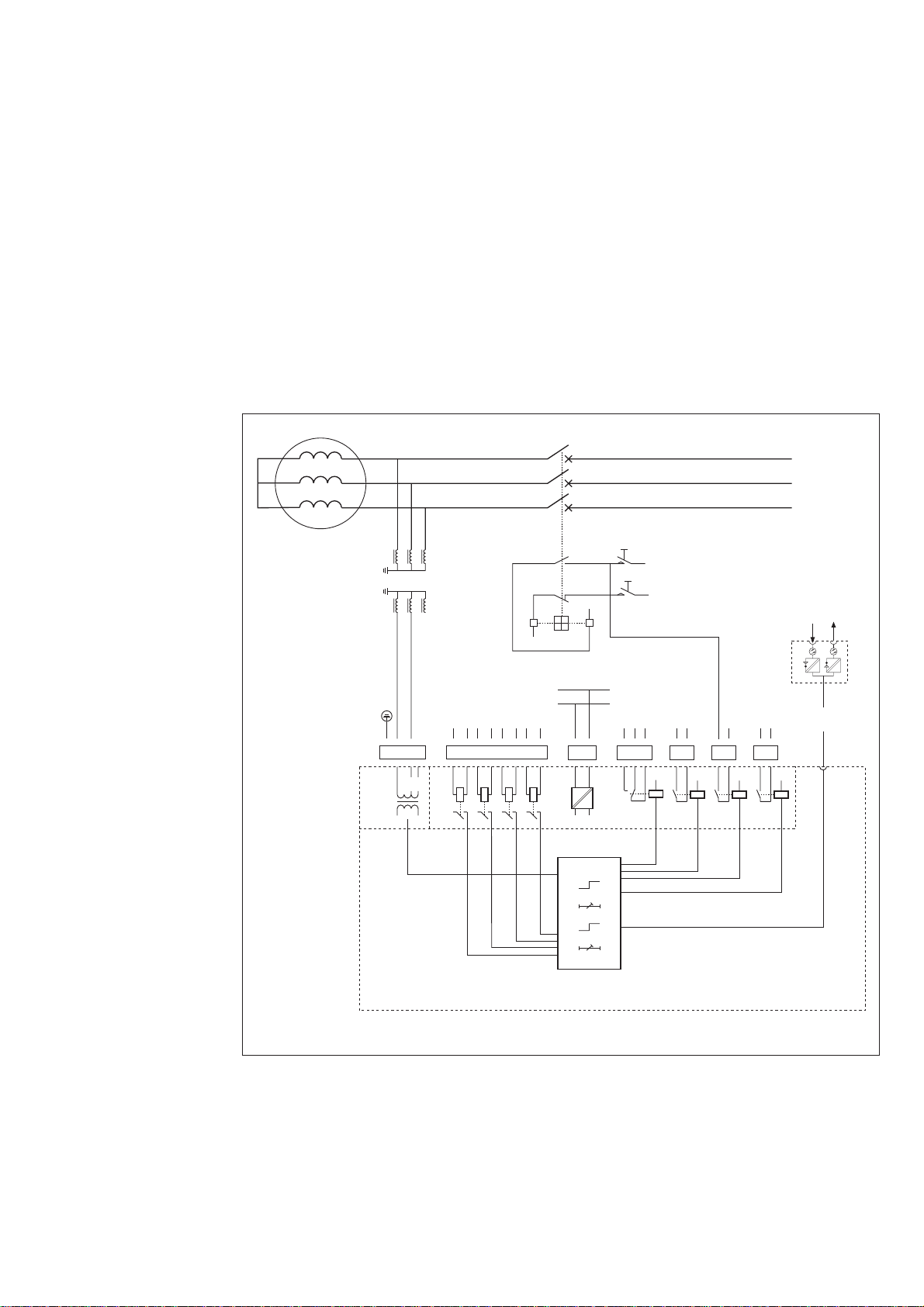
The output signals SS1 and TS1...TS2 of the
mother PC board control an output relay with
the same designation. The operation of a stage
is not fixed to a specific output relay, but can be
configured for the desired relay. However, it
should be noted that the output relays TS1 and
TS2 can be used for circuit breaker control. The
configuration of the switchgroups is described
in the module-specific manuals.
The switchgroups of the relay modules are used
for configuring the external control inputs,
which can be used for blocking one or several
protection stages, resetting operation indicators
or selecting second settings, etc.

7
Technical data
(modified 2001-04)
Voltage input
Rated voltage Un(programmable) 100 V (110 V, 115 V, 120 V)
Terminal numbers 13-14
Continuous voltage withstand 2 x Un
Rated burden of voltage input at Un<0.5 VA
Output contacts
Trip contacts
Terminal numbers 85-86, 87-88
Rated voltage 250 V ac/dc
Continuous current carrying capacity 5 A
Make and carry 0.5 s 30 A
Make and carry 3 s 15 A
Breaking capacity for dc when the control circuit time
constant L/R ≤40 ms at the control voltage levels
- 220 V dc 1 A
- 110 V dc 3 A
- 48 V dc 5 A
Signal contacts
Terminal numbers 68-69, 70-71-72
Rated voltage 250 V ac/dc
Continuous current carrying capacity 5 A
Make and carry 0.5 s 10 A
Make and carry 3 s 8 A
Breaking capacity for dc when the control circuit time
constant L/R ≤40 ms at the control voltage levels
- 220 V dc 0.15 A
- 110 V dc 0.25 A
- 48 V dc 1 A
External control inputs
Blocking/control (BS1...BS4)
Terminal numbers 10-11, 22-23, 45-46, 47-48
External control voltage 18...250 V dc or 80...250 V ac
Current drain of activated control input 2...20 mA
Power supply module
SPTU 240R4
Rated voltage Un= 100/120/230 V ac
Un= 110/125/220 V dc
Operative range U = 80...265 V dc
SPTU 48R4
Rated voltage Un= 24/48/60 V dc
Operative range U = 18...80 V dc
Power consumption under quiescent/
operation conditions 7 W/9 W

8
Combined frequency and rate of change of frequency relay module SPCF 1D15
- see "Technical data" in the description of the module.
Data communication
Transmission mode Fibre-optic serial bus
Coding ASCII
Data transfer rate, selectable 4800 Bd or 9600 Bd
Bus connection modules for fibre-optic data transfer
- for plastic core cables SPA-ZC 21 BB
- for glass-fibre cables SPA-ZC 21 MM
Modules with internal power supply unit
- for plastic core cables SPA-ZC 17 BB
- for glass-fibre cables SPA-ZC 17 MM
Insulation Tests *)
Dielectric test IEC 60255-5 2 kV, 50 Hz, 1 min
Impulse voltage test IEC 60255-5 5 kV, 1.2/50 µs, 0.5 J
Insulation resistance measurement IEC 60255-5 >100 MΩ, 500 Vdc
Electromagnetic Compatibility Tests *)
High-frequency (1 MHz) burst disturbance test
IEC 60255-22-1
- common mode 2.5 kV
- differential mode 1.0 kV
Electrostatic discharge test IEC 60255-22-2 and
IEC 61000-4-2
- contact discharge 6 kV
- air discharge 8 kV
Fast transient disturbance test IEC 60255-22-4
and IEC 61000-4-4
- power supply 4 kV
- I/O ports 2 kV
Mechanical environmental tests
Vibration test, IEC 60255-21-1 class 2
Chock/bump test, IEC 60255-21-2 class 2
Seismic test, IEC 60255-21-3 class 2
Environmental conditions
Service temperature range -10... +55°C
Transport and storage temperature range -40...+70°C
Temperature influence ±0.05‰/frequency measurement
in the range -10°C…+55°C
<0.2%/°C, voltage measurement
Relative humidity 93...95%, +55°C, 6 cycles
Degree of protection by enclosure of flush-
mounting relay case IP54
Weight of fully equipped relay 3 kg
*) The tests do not apply to the serial port, which is used exclusively for the bus connection module.

9
Example of
application
Example:
Frequency relay
SPAF 140 C used
for generator and
turbine protection
Normally, the frequency of the generator is de-
termined by the external network. If power con-
sumption exceeds the power generated, there
will be a power deficiency and, as a result, a fre-
quency decline. As the frequency drops, the
regulator tries to boost the capacity of the gen-
erator prime mover, causing the frequency to
return to normal. Correspondingly, if power
consumption is smaller than power generation,
the frequency of the network increases.
Unless it is possible to increase the capacity of
the prime mover so that it correspond to the
load, the power deficiency remains permanent
and the network frequency starts declining.
Under normal conditions, the rate of the fre-
quency drop automatically slows down, and may
even stop, because power consumption gener-
ally decreases as the frequency falls (compare
pump and squirrel-cage motor). Sometimes, for
instance in island operation, the network fre-
quency can drop to a level that is hazardous to
the turbine of the generator. Mechanical vibra-
tion of the turbine blades due to underfrequency
may break the blades.
A moderate level of overfrequency does not
damage the generator but, for instance, a sud-
den load disconnection may cause the system
to accelerate so fast that the speed regulation
does not respond fast enough, and the genera-
tor and the prime mover reach dangerous rota-
tional speeds.
The frequency relay SPAF 140 C can be used
to protect the generator and the turbine against
both overfrequency and underfrequency.
IRF
SS1
TS1
SS2
TS2
SS3
TS3
SS4
TS4
I/O
BS1
BS2
BS3
BS4
BS5
U1
4
f
4
df/dt
48 47 46 45 23 22 11 10
BS4 BS3 BS2 BS1
X0 63 13 14 16 62 61
U
aux
+-
=
~_
+ (~)
- (~)
70 71 72 68 69 85 86 87 88
IRF SS1 TS1 TS2 SERIAL
PORT
(SPA)
+ + +
SPA-ZC_
Rx Tx
U3
+
U2
100 V
Not
Used
a
n
d
N
A
+
01
-
-
+
0
+
1
Alarm Alarm
Fig. 4. Frequency relay SPAF 140 C used for the protection of a generator and a turbine.

10
Four protection stages, two signalling and two
tripping, are used in the example described.
Stage 2 produces an alarm signal, if the fre-
quency exceeds the rated frequency, and stage
3, correspondingly, if the frequency falls below
the rated frequency. The selected alarm limits
allow the generator and the turbine to operate
for a long time with the concerned frequency,
without any risk of being damaged.
Should the frequency decrease or increase to a
dangerous level, the relay provides a trip signal.
The protection also includes a blocking input
which can be used for blocking the relay opera-
tion, for instance, during the start of the gen-
erator.
The start values and operate times of the pro-
tection stages and the timers controlling the in-
dividual circuit breakers are shown in Fig. 5.
The designations used in Fig. 5 refer to Fig. 4.
Stage Operate Delay Timer Relay output Function
value (Hz)
1 53.0 0.30 t1TS1 Tripping
2 51.5 1.00 t2SS1 Overfrequency alarm
3 48.5 1.00 t3TS2 * Underfrequency alarm
4 47.0 0.30 t4TS1 Tripping
*)The trip contact TS2 is used for underfrequency alarm, because only one trip contact is
required for the protection.
Fig. 5. Setting of the protection stages of frequency relay SPAF 140 C used for the protection of a
generator and a turbine.
In the case described in the example the switches of the frequency relay SPAF 140 C can be set as
follows:
Setting of t, relay module SPCF 1D15
Switch- Serial comm. Checksum Operation
group parameter
SGF1 S84 1 Only frequency function
SGF2 S85 1 Only frequency function
SGF3 S86 1 Only frequency function
SGF4 S87 1 Only frequency function
SGF5 S88 255 Outputs continuously operated
SGF6 S89 2 TS1 connected to LED indicator TRIP
SGF7 S90 0 Un= 100 V
SGB1 S91 15 Blocking via external control signal BS1
SGB2 S92 0 External control signal BS2 not in use
SGB3 S93 0 External control signal BS3 not in use
SGB4 S94 0 External control signal BS4 not in use
SGB5 S95 0 External control signal BS5 not in use
SGB6 S96 15 Undervoltage blocking to all stages
SGR1 S97 2 Overfrequency trip signal to trip contact TS1
SGR2 S98 0 Not in use
SGR3 S99 1 Underfrequency alarm signal to signal contact SS1
SGR4 S100 0 Not in use
SGR5 S101 8 Underfrequency alarm signal to trip contact TS2
SGR6 S102 0 Not in use
SGR7 S103 2 Underfrequency trip signal to trip contact TS1
SGR8 S104 0 Not in use
SGR9 S105 0 No recovery function

11
Testing The relay should be subjected to regular tests in
accordance with national regulations and in-
structions. The manufacturer recommends an
interval of five years between the tests.
The test should be carried out as a primary test,
which includes the entire protection arrange-
ment, from the instrument transformers to the
circuit breakers.
The test can also be carried out as a secondary
injection test. Then the relay has to be discon-
nected during the test procedure. However, it is
recommended to check the function of the sig-
nal and trip circuits as well.
Note!
Make sure that the secondary circuits of the
current transformers under no condition open
or are open, when the relay is disconnected and
during the test procedure.
The test is recommended to be carried out us-
ing the normal setting values of the relay and
the energizing inputs used. When required, the
test can be extended to include more setting
values.
As the settings of the relay modules affect the
operation of the relay (overfrequency/under-
frequency relay) and thus also the test proce-
dure, these instructions describe the general fea-
tures of the test procedure. The test procedure
presented here applies to the underfrequency re-
lay. A voltage supply unit allowing voltage and
frequency to be regulated is recommended to
be used. In addition, instruments for measur-
ing voltage, frequency and time are required.
During the test procedure the relay records fre-
quencies, rates of change of frequency, voltages
and relay operations. If the recorded data is used
for the collection of information for longer time
periods (for example, AR counters), these re-
gisters should be read before the test procedure
is started. After the test the registers are reset
and, if required, the readings of the AR counters
can be restored.
The relay settings may have to be changed dur-
ing testing. A PC program is recommended to
be used to read the relay settings before the test
is started.
Testing of the
combined frequency
and rate of change of
frequency relay
module SPCF 1D15
General
The protection stages are tested with respect to:
- start value
- trip time
- trip indication, output relay operation
Start value Test the start value by gradually dropping the
frequency, starting from the rated value, until
the relay starts. Record the frequency required
for starting. The value should be within the per-
mitted tolerances.
If the resetting value is to be tested as well, drop
the frequency, until the relay starts, and then in-
crease the frequency again, until the relay resets.
When multi-stage protection relays are tested,
the operation of the higher-set stages may cause
problems to the testing of lower-set stages. Then
it is generally necessary to delay the operation
of the higher-set stages by changing the setting
values, or totally block the operation of the
higher stages by reconfiguring the SGR switches.
In such a case it is recommended to start the
test from the lowest stage and then proceed to
higher-set stages. The advantage of this method
is that the original settings of the stages really
are restored, because otherwise the test cannot
be carried out successfully.
Trip time Apply a voltage of rated frequency to the relay.
Then drop the frequency of the voltage to a value
below the setting value. The frequency of the
supply voltage should be such that the differ-
ence between the trip level and the frequency
of the supply voltage is about twice the differ-
ence between the rated frequency and the trip
level. However, the absolute value of the rate of
change of frequency must not exceed 70 Hz/s,
because the relay perceives such a situation as a
disturbance and delays tripping by two cycles.
The operate time is the time from the moment
the frequency starts changing, until the relay
operates. The accuracy of the operate times
should be within the permitted tolerances.
The resetting time is the time measured from
the moment the current switch is opened, until
the relay resets.

12
Maintenance
and repairs
When the protection relay is used under the
conditions specified in "Technical data", it re-
quires practically no maintenance. The relay
includes no parts or components that are sensi-
tive to physical or electrical wear under normal
operating conditions.
Should the temperature and humidity at the
operating site differ from the values specified,
or the atmosphere contain chemically active
gases or dust, the relay should be visually in-
spected in association with the secondary test-
ing of the relay. This visual inspection should
focus on:
- Signs of mechanical damage to relay case and
terminals
- Collection of dust inside the relay case; remove
with compressed air
- Signs of corrosion on terminals, case or inside
the relay
If the relay malfunctions or the operating val-
ues differ from those specified, the relay should
be overhauled. Minor measures can be taken
by the customer but any major repair involving
the electronics has to be carried out by the
manufacturer. Please contact the manufacturer
or his nearest representative for further infor-
mation about checking, overhaul and recalibra-
tion of the relay.
The protection relay contains circuits that are
sensitive to electrostatic discharge. If you have
to withdraw a relay module, ensure that you are
at the same potential as the module, for instance,
by touching the case.
Note!
Protection relays are measuring instruments and
should be handled with care and protected
against moisture and mechanical stress, espe-
cially during transport.
Spare parts Combined frequency and rate of change of frequency relay module SPCF 1D15
Combined power supply and I/O module
- U = 80...265 V ac/dc (operative range) SPTU 240R4
- U = 18...80 V dc (operative range) SPTU 48R4
Case (including connection module) SPTK 1E18
Bus connection module SPA-ZC 17_
SPA-ZC 21_
Order numbers
(modified 98-03)
Frequency relay SPAF 140 C without test adapter: RS 452 001-AA, CA
Frequency relay SPAF 140 C with test adapter RTXP 18: RS 452 201-AA, CA
The letter combinations of the order number indicate the auxiliary voltage Uaux of the protection
relay. The rated frequency is selected in the software.
AA: Uaux = 80...265 V ac/dc
CA: Uaux = 18...80 V dc

13
Dimension
drawings and
mounting
The basic model of the protection relay case is
designed for flush-mounting. When required,
raising frames can be used for reducing the
mounting depth of the case: type SPA-ZX 111
reduces the depth by 40 mm, type SPA-ZX 112
by 80 mm and type SPA-ZX 113 by 120 mm.
A relay case type SPA-ZX 110 is available for
surface mounting.
Fig. 12. Dimension and mounting drawings for frequency relay SPAF 140 C.
The relay case is made of profile aluminium and
painted grey.
The rubber gasket fitted to the mounting collar
provides an IP 54 degree of protection by en-
closure between the relay case and the mount-
ing base.
The hinged cover of the case is made of trans-
parent, UV-stabilized polycarbonate polymer
and provided with two sealable locking screws.
The rubber gasket of the cover provides an IP
54 degree of protection between the case and
the cover.
The required input and output circuits are con-
nected to the screw terminals on the rear panel.
Each terminal screw is dimensioned for one wire
of maximum 6 mm2or two wires of maximum
2.5 mm2. Some of the control inputs are situ-
ated in the detachable 6-pole connector.
The 9-pole D-type connector is intended for
serial communication.
Raising frame
SPA-ZX 111
SPA-ZX 112
SPA-ZX 113
176
136
96
74
114
154
ab
ab
Panel cut-out
129 ±1
139 ±1
142
162
136
30 34
250
186
216
Ordering
information
Example
1. Number and type designation 10 SPAF 140 C units
2. Order number RS 454 001 -AA
3. Auxiliary voltage Uaux = 110 V dc
4. Accessories 10 bus connection modules SPA-ZC 17 MM2A
6. Special requirements –


SPCF 1D15
TRIP
RESET
STEP
0024C
PROGRAM
IRF
f
U
f
<
>
<
>
d
f
d
t
SGR
SGB
SGF
[ ]
n
f
U
/
<
Hz
n
U
[ ]
f
Hz
∆
[ ]
r
t
s
[ ]
d
f
d
t
/ /
Hz s
[ ]
1
f
Hz
[ ]
4
f
Hz
[ ]
3
f
Hz
[ ]
2
f
Hz
[ ]
1
t
s
,1
t
,
[ ]
2
t
s
,2
t
,
[ ]
3
t
s
,3
t
,
[ ]
4
t
s
,4
t
,
SPCF 1D15
Combined Frequency and Rate of
Change of Frequency Relay Module
User´s manual and Technical description

2
SPCF 1D15
Combined Frequency
and Rate of Change of
Frequency Relay Module
Contents Features .......................................................................................................................... 2
Description of operation ................................................................................................. 3
Filtering of energizing inputs ..................................................................................... 3
Frequency measurement ............................................................................................ 3
Rate of change of frequency measurement ................................................................. 3
Overfrequency ........................................................................................................... 3
Underfrequency ......................................................................................................... 4
Rate of change of frequency....................................................................................... 4
Recovery function...................................................................................................... 4
Output signals ........................................................................................................... 5
Second settings .......................................................................................................... 5
Resetting.................................................................................................................... 5
Block diagram ................................................................................................................. 6
Front panel .....................................................................................................................7
Operation indicators ....................................................................................................... 8
Settings (modified 2004-03) ............................................................................................ 9
Configuration switches (modified 1997-01) .................................................................. 10
Measured data............................................................................................................... 14
Recorded data (modified 2002-06) ................................................................................ 14
Menu chart (modified 1997-01) .................................................................................... 16
Technical data (modified 2004-03) ................................................................................ 18
Serial communication parameters ................................................................................. 19
Event codes .............................................................................................................. 19
Remote transfer data (modified 2004-03)................................................................. 21
Fault codes .................................................................................................................... 26
Features Four protection stages, each of which can be
used for either overfrequency or underfrequency
protection. Any stage can be set out of opera-
tion.
Each protection stage incorporates a rate of
change of frequency function, which can be used
alone or together with the overfrequency/under-
frequency function. When required, the rate of
change of frequency function can be discon-
nected.
Each protection stage is provided with two
adjustable timers
Programmable recovery function
Programmable undervoltage blocking
Programmable rated frequency
Output relay matrix allowing any trip signal to
be linked to the desired output signal
Digital display of measured and set values and
data recorded at the instant of a fault
Reading and writing of setting values via dis-
play and front panel push-buttons, a PC with
setting software, or from higher system levels
over the serial bus
Continuous self-supervision of electronics and
microprocessor operation. On detection of a
permanent fault, the self-supervision system
delivers a control signal to the signal relay and
blocks the other outputs.
1MRS 750583-MUM EN
Issued 1996-11-05
Modified 2004-03-16
Version D
Checked PS
Approved MÖ
Data subject to change without notice

3
Description of
operation
Filtering of
energizing input
The relay module contains two filters: a lowpass
filter for voltage measurement and a bandpass
filter for frequency measurement. The purpose
of the filters is to suppress the harmonics of the
measured signal. Fig. 1 illustrates harmonics
suppression as a function of frequency.
Fig. 1. Harmonics suppression of the energizing input of relay module SPCF 1D15
Frequency
measurement
Frequency measurement is based on measuring
the time between the zero crossings of a signal.
The frequency is calculated as a moving aver-
age so that the length of the averaging can be
selected by the customer. The number of cycles
to be used for the calculation can be selected in
the range from 3 to 20 cycles.
When the calculation is based on three cycles,
the measurement response time will be short
and, consequently, the trip time as well. On the
other hand, when twenty cycles are used the
response time will be long, but the effect of the
noise possibly occurring in the signal will be
small.
In addition to the filtering described above, the
trip time of the relay is affected by the rated
frequency selected. The minimum trip time of
the relay is obtained from the formula:
tmin = n + [ms],
where n is the number of cycles used and fnthe
rated frequency. However, the minimum trip
time is at least 100 ms. Should a trip time shorter
than the calculated time be set for the relay, the
setting will be ignored.
-3fn+ 254 85
10 2
Rate of change
of frequency
measurement
The calculation of the rate of change of fre-
quency is based on two successive frequency
values, calculated as moving values over three
cycles. Changing of the number of cycles to be
used in the frequency measurement does not
affect the measurement of the rate of change of
frequency.
When the rate of change of frequency function
is used, the minimum trip time is 150 ms.
Overfrequency When the setting value is above the rated fre-
quency programmed, the protection stage op-
erates as an overfrequency stage. The setting
value cannot be the same as the rated frequency.
Once the frequency exceeds the setting value of
the stage concerned, the stage starts and, at the
same time, a start indicating operation code
appears on the display. Should the stage still be
operated, when the operate time of the stage
expires, it trips, delivering the configured trip
signal.
The tripping of the stages can be prevented by
applying an external control signal BS1...BS5
to the relay module. The switchgroups SGB1...
SGB5 are used for configuring the external
blocking signals. In addition, the undervoltage
blocking function (switchgroup SGR6) can be
used for blocking the stage.
0
A [dB]
f [Hz]
10 100 10001
-100
10
50 60 150 180 250 300
Voltage measurement
Frequency measurement

4
Underfrequency A protection stage has the function of an under-
frequency stage, when the setting value is be-
low the rated frequency. The setting value can-
not be the same as the rated frequency.
The underfrequency stage operates in the same
way as the overfrequency stage, but starts, when
the frequency falls below its setting value.
Rate of change
of frequency
Each protection stage incorporates a rate of
change of frequency (df/dt) function, which can
be used alone or together with the frequency
function.
The operation principle of the rate of change of
frequency function is the same as that of the
overfrequency/underfrequency stage.This means
that if the frequency setting of this particular
stage is above the rated frequency, the rate of
change of the frequency has to be positive to
make the df/dt function become true. Corre-
spondingly, the rate of change of frequency has
to be negative, if the stage has the function of
an underfrequency stage. The same principle
also applies, when the df/dt function is used
alone, without the frequency function.
When the df/dt function is used alone, the stage
starts once the absolute value of the rate of
change of the frequency is greater than the set-
ting value of the stage. At the same time as the
stage starts, a start indicating code appears on
the display. Should the protection stage still be
operated, when the set operate time expires, it
trips, delivering the programmed trip signal.
When the df/dt function is used together with
the frequency function, the stage starts when
the operation criteria for both functions, i.e. the
df/dt function and the frequency function, are
fulfilled at the same time. Should the protec-
tion stage still be operated (both conditions for
operation fulfilled), when the set operate time
expires, the stage trips, delivering the configured
trip signal.
The rate of change of frequency function is rec-
ommended to be used together with the fre-
quency function.
The minimum trip time is 150 ms, when the
rate of change of frequency function is used. This
means that if the rate of change of frequency
function is enabled with the SGF switches, the
minimum operate time of the timer is 150 ms.
When the frequency function is used alone, the
minimum operate time is 100 ms.
Recovery function In addition to the four protections stages the
module incorporates a recovery stage. This re-
covery stage can be used to control the desired
output relay when, after tripping of the protec-
tion stage, the frequency returns to normal and
remains within the setting range throughout the
operate time of the recovery function.
The permitted limits for recovery is defined as
a frequency window, the centre of which is the
programmed rated frequency of the module.
The limit to be set is the maximum permitted
frequency deviation from the rated frequency
(fn±fr) of the module.
The timer of the recovery function resets and
remains reset as long as one single protection
stage selected is in a tripped condition. At the
same time the normally activated recovery out-
put resets. After resetting, the operate time is
calculated for the time when the frequency re-
mains within the specified limits. When the
operate time elapses, the recovery function op-
erates and the output is activated. At the same
time, an operation code indicating activation
of the recovery function appears on the display.
An external control signal can be used to pre-
vent both recovery functions in progress and the
start of new ones.

5
Output signals Switchgroups SGR1...SGR9 can be used to link
the start or trip signal of any protection stage to
the desired outputs SS1...SS4 or TS1...TS4.
Two output operation modes, i.e. a continuously
energized or a pulse-mode output operation can
be selected for the output signals SS1...SS4 and
TS1...TS4(switches SGF5/1...8). A continu-
ously energized output remains active as long
as the protection stage controlling it is active.
When a pulse output is used, the output remains
active only as long as the preprogrammed pulse
is present, even though the protection stage con-
trolling the output stays active.
Resetting of the output relays appears from the
table in paragraph "Resetting".
The TRIP indicator on the front panel can be
set to indicate activation of any output signal.
The operation indicator remains lit, when the
output signal resets. The switchgroup SGF6 is
used for selecting these functions.
Second setting Either the main settings or the second settings
can be selected as the actual setting values used.
Shifting between main setting and second set-
ting values can be done in three ways as fol-
lows:
1. Over the serial bus, using command V150.
2. By using any external control signal.
3. Via the push-buttons of the relay module, in
subregister 4 of register A. When the value
of subregister 4 is 0, the main settings are
used and when the value is 1, the second set-
ting values are used.
The main and second settings can be read and
set over the serial bus, by using the S param-
eters. The push-buttons on the front panel can
be used for reading and setting only the actual
setting values used. When the second settings
are in use, the indicator of the selected setting is
flashing.
Note.
If external control signals have been used for
selecting the main setting or the second setting,
shifting between the settings cannot be done
over the serial bus or with the push-buttons on
the front panel.
Resetting The push-buttons on the front panel, an exter-
nal control signal or a serial communication pa-
rameter can be used for resetting the operation
codes on the display and the registers of the re-
lay module. See the table below.
Way of resetting Resetting of indicators Resetting of registers
RESET x
PROGRAM (display dark) x
RESET & PROGRAM x x
External control signal BS1...5,
when
SGF_/7 = 1 x
SGF_/8 = 1 x x
Parameter V102 x x

6
Block diagram
df
dt >
<
f>
<
& 1
SGF1/3
SGF1/2
SGF1/1
SGR1/x
SGR2/x
df
dt >
<
f>
<
& 1
SGF2/3
SGF2/2
SGF2/1
SGR3/x
SGR4/x
df
dt >
<
f>
<
& 1
SGF3/3
SGF3/2
SGF3/1
SGR5/x
SGR6/x
df
dt >
<
f>
<
1
SGF4/2
SGF4/1
SGR7/x
SGR8/x
&
(fn-fr)>
(fn+fr)<
SGR9/x
1
2
3
4
5
6
7
8
1
SGF6/1
2
3
4
5
6
7
8
SS1
TS1
SS2
TS2
SS3
TS3
SS4
TS4
S
R
TRIP
SGF5/1
SGF6/2
SGF5/2
SGF6/3
SGF5/3
SGF6/4
SGF5/4
SGF6/5
SGF5/5
SGF6/6
SGF5/6
SGF6/7
SGF5/7
SGF6/8
SGF5/8
t
t
t
t
t
t
t
t
SGF4/3
SGB1/x
BS1
SGB2/x
BS2
SGB3/x
BS3
SGB4/x
BS2
SGB5/x
BS5
U< SGB6/x
T#f
∩#
U12
1
0
&
t1
t1'
t2
t2'
t3
t3'
t4
t4'
Set
Reset
Count
Start
Count
t
Hardware
System restart
Recovery function
Reset trip indicators
and registers
Settings (main/2nd) SGF 1...4/4 = 1 Operation indicator latched
Un 100V 110V 115V 120V
Switch
SGF 7/1 0 1 0 1
SGF 7/2 0 0 1 1
Un
SGF 7/3 = 1 Un= 3
Reset
button
Fig. 2. Block diagram for the combined frequency and rate of change of frequency relay module
SPCF 1D15
U12 Phase-to-phase voltage
BS1...BS5 External control signals
SGF1...SGF7 Switchgroups for relay configuration
SGB1...SGB6 Switchgroup for external control signals
SGR1...SGR9 Switchgroup for output relay matrix
TS1...TS4 Output signals
SS1...SS4
TRIP Red operation indicator
Note!
All input and output signals of the relay mod-
ule are not necessarily wired to the terminals of
each protection relay containing this module.
The signals wired to the terminals are shown in
the signal diagram of the concerned protection
relay.
Table of contents
Other ABB Relay manuals
Popular Relay manuals by other brands

Basler
Basler H12345678 R U instruction manual

schmersal
schmersal SRB 031MC operating instructions

TECO
TECO SG2-DNET user manual

Mitsubishi Electric
Mitsubishi Electric MELSEC-WS user manual

Taco
Taco SR501-EXP-4 instruction sheet

Rockwell Automation
Rockwell Automation A-B 193 E1 PLUS Application and Installation