ABB REU 523 Product manual

ABB Automation
REU 523
Combined Overvoltage and
Undervoltage Relay
Technical Reference Manual


ABB Automation 3
Combined Overvoltage and
Undervoltage Relay
Technical Reference Manual
REU 523
1MRS 750942-MUM
Issued: 07.06.99
Version: A/16.11.99
Checked: H.S.
Approved: S-M.H.
We reserve the right to change data without prior notice.
Contents
1. Introduction ...............................................................................5
1.1. About this manual .........................................................................5
1.2. The use of the relay ......................................................................5
1.3. Features ........................................................................................5
1.4. Guarantee .....................................................................................6
2. Safety Information .....................................................................7
3. Instructions ................................................................................8
3.1. Application .....................................................................................8
3.2. Requirements ................................................................................8
3.3. Configuration .................................................................................9
4. Technical Description .............................................................10
4.1. Functional description .................................................................10
4.1.1. Product functions .............................................................10
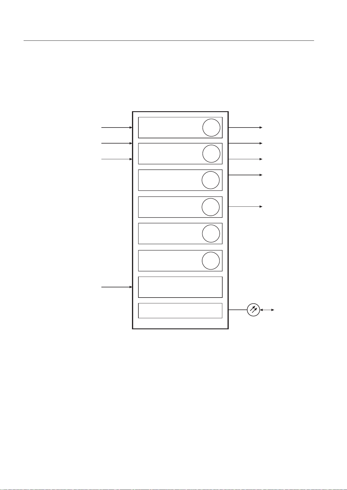
4.1.1.1. Schema of product functions ..............................10
4.1.1.2. Overvoltage, undervoltage and positive-phase-
sequence ............................................................10
4.1.1.3. Inputs .................................................................11
4.1.1.4. Outputs ...............................................................11
4.1.1.5. Circuit-breaker failure protection ........................11
4.1.1.6. Disturbance recorder ..........................................11
4.1.1.7. MMI module .......................................................11
4.1.1.8. Self-supervision ..................................................11
4.1.2. Configuration ....................................................................12
4.1.3. Protection .........................................................................13
4.1.3.1. Block diagram ....................................................13
4.1.3.2. Overvoltage unit .................................................13
4.1.3.3. Undervoltage unit ...............................................14
4.1.3.4. Positive-phase-sequence protection ..................15
4.1.3.5. Time/voltage characteristics ...............................16
4.1.3.6. Settings ..............................................................19
4.1.3.7. Technical data of protection functions ................27
4.1.4. Monitoring ........................................................................28
4.1.5. Self-supervision (IRF) ......................................................29
4.1.6. I/O test .............................................................................29
4.1.7. Disturbance recorder .......................................................29
4.1.7.1. Function .............................................................29
4.1.7.2. Recorder data ....................................................30

4ABB Automation
1MRS 750942-MUM
Combined Overvoltage and Undervoltage Relay
Technical Reference Manual
REU 523
4.1.7.3. Control and indication of recorder status ...........30
4.1.7.4. Triggering ...........................................................30
4.1.7.5. Settings and unloading ......................................30
4.1.7.6. Event code .........................................................31
4.1.8. Recorded data .................................................................31
4.1.9. External serial communication .........................................32
4.1.9.1. Communication ports .........................................32
4.1.9.2. Event codes .......................................................33
4.1.9.3. Remote transfer data .........................................35
4.1.10.Relay parameterization ....................................................42
4.2. Design description ......................................................................42
4.2.1. Input / output connections ...............................................42
4.2.2. Serial communication connections ..................................45
4.2.3. Technical data .................................................................46
5. Ordering Information ............................................................. 50
6. References .............................................................................. 51
7. Index ........................................................................................ 52
8. Check Lists ............................................................................. 54
9. Customer Feedback ............................................................... 57

1MRS 750942-MUM Combined Overvoltage and Undervoltage Relay
Technical Reference Manual
REU 523
ABB Automation 5
1. Introduction
1.1. About this manual
This manual is intended to provide the user with thorough information on the relay
REU 523 and its applications. The focus in the manual is on technical description of
the relay.
Instructions for using the Man-Machine Interface (MMI) are found in separate
“Operator’s Manual” and for installation in “Installation Manual”.
1.2. The use of the relay
The three-phase voltage relay REU 523 is intended to be used for overvoltage and
undervoltage protection and supervision in distribution substations. It can also be
used for protection of generators, motors and transformers.
The relay featurestwo over- and two undervoltage protection functions that evaluate
the fundamental wave of the three phase-to-phase voltages but can also be
programmed to evaluate single phase-to-phase voltage. One of the undervoltage
stages can alternatively be set to evaluate the positive-phase-sequence voltage.
The protection relay REU 523 is based on a microprocessor environment. A self-
supervision system monitors continuously the operation of the relay.
The MMI includes an LCD display which makes the local use of the relay safe and
easy.
Local control of the protection relay can be carried out with a portable computer
connectedtothefrontconnector andremotecontrolvia therearconnectorconnected
to the distribution automation system through the serial interface and fibre-optic bus.
1.3. Features
• Overvoltage and undervoltage protection
• Single- or three-phase operation
•High-set overvoltage stage with definite-time or inverse definite minimum time
(IDMT) characteristic
•Low-set overvoltage stage with definite-time or IDMT characteristic
•High-set undervoltage stage with definite-time or IDMT characteristic
•Low-set undervoltage stage with definite-time or IDMT characteristic
•Positive-phase-sequence protection
•Settable drop-off/pick-up ratio for low-set overvoltage and low-set undervoltage
stages
• Circuit-breaker failure protection unit (CBFP)
• Disturbance recorder
• All settings can be modified with a personal computer
• Settings are stored in a non-volatile memory and remain even in case of power
supply failure
• MMI with an alphanumeric LCD and manoeuvring buttons

6ABB Automation
1MRS 750942-MUM
Combined Overvoltage and Undervoltage Relay
Technical Reference Manual
REU 523
• Two normally open power output contacts
• Two change-over type signal output contacts
• Output contact functions freely configurable for desired operation
• Three accurate voltage inputs
• Galvanically isolated binary input with a wide input voltage range
• Optical PC-connector for two-way SPA-bus data communication (front)
• RS-485 connector (rear), for system communication
• Continuous self-supervision of hardware and software. At a permanent fault all
stages and outputs are blocked.
• Rated frequency user-selectable 50/60 Hz
• Nominal voltage user-selectable 100/110/115/120 V
• User-selectable password protection for MMI
• Display of primary voltage values
1.4. Guarantee
Please inquire the guarantee of your nearest ABB representative.

1MRS 750942-MUM Combined Overvoltage and Undervoltage Relay
Technical Reference Manual
REU 523
ABB Automation 7
2. Safety Information
Dangerous voltages can occur on the connectors, even though the
auxiliary voltage is disconnected.
National and local electrical safety regulations must always be
followed.
The frame of the protection relay has to be carefully earthed.
Only a competent electrician is allowed to carry out the electrical
installation.
!
!
!

8ABB Automation
1MRS 750942-MUM
Combined Overvoltage and Undervoltage Relay
Technical Reference Manual
REU 523
3. Instructions
3.1. Application
The overvoltage and undervoltage relay REU 523 is a secondary relay that is
connected to the voltage transformers of an object to be protected. It is designed for
overvoltage and undervoltage protection and supervision in distribution substations.
Other application areas are overvoltage and undervoltage protection of generators,
motors and transformers.
The three-phase overvoltage and undervoltage stages continuously measure the
phase-to-phase voltages of the system. On detection of a fault the relay starts, trips
the circuit breaker, provides alarms, records fault data etc., in accordance with the
application and the configured relay functions.
Both the overvoltage and the undervoltage units include two protection stages: low-
set stages U> and U<, and high-set stages U>> and U<<. Each protection stage can
be given a definite-time or an inverse definite minimum time (IDMT) characteristic.
The start and operation of the high-set and low-set undervoltage stages can be
blockedwhen the measured voltages are under 0.2 x Un. Further, theoperation of all
protection stages can be blocked separately by means of an external binary input
signal.
The high-set undervoltage stage can be set to operate either based on conventional
undervoltage measurement or on the calculated positive-phase-sequence voltage
U1s. Selecting the positive-phase-sequence operation automatically deselects the
conventional high-set undervoltage stage operation, and vice versa.
The operation of the stage U< can be blocked by the start of the stage U<<. The high-
set stages of the overvoltage and undervoltage units can be deselected from
operation separately.
The protection functions are independent of each other unless configured to be
dependent, and they have their own setting groups as well as data recording. The
over- and undervoltage functions use conventional voltage transformer
measurement.
Output contact matrix allows any start or trip signal from the protection stages to be
routed to the desired output contact.
3.2. Requirements
When the protection relay is operating under conditions specified below (see also
“Technical data” beginning from page 47), the relay is practically maintenance-free.
The relay includes no partsor componentssubject toabnormal physical orelectrical
wear under normal operating conditions.

1MRS 750942-MUM Combined Overvoltage and Undervoltage Relay
Technical Reference Manual
REU 523
ABB Automation 9
Environmental conditions
3.3. Configuration
Setting and connection example
The appropriate configuration of the output contact matrix enables using the trip
signals from the over- and undervoltage stages for operating two different circuit
breakers. The start signals can be used for blocking co-operating protection relays,
for signalling and for initiating autoreclosing.
Figure 3.3.-1 represents the relay with the default configuration.
)LJ &RQQHFWLRQGLDJUDPRIWKHRYHUYROWDJHDQGXQGHUYROWDJHUHOD\
• Specified ambient service temperature range -10...+55 °C
• Temperature influence on the operating values of the relay
within the specified ambient service temperature range 0.1% / °C
• Transport and storage temperature range -40...+70 °C
L1
L2
L3
ConD1_U_523
Uaux
1
2
3SGB1
SGB1
SGB1
~
~
X
3
X
3
2
X
2
X
1
X
1
X
X
4
X
4
5 6 3 4
13 14 15
1 2
17 18
1 3 4 6 7 9
SGB1
SGB1
5
6
10 11 12 7 8 9
X2.1
X1.1
100 V
110 V
115 V
120 V
3U<
3U<<
SGB1
7
SGB1
8
X
4
X
4
X
3
X
3
2
X
2
X
1
X
1
X
+ -
3U>
3U>>
100 V
110 V
115 V
120 V
100 V
110 V
115 V
120 V
a
PO1PO2
IRF
BI SO1SO2
IRF
TRIP
SGR1
SGR2
SGR3
SGR4
START
START
TRIP
START
START
TRIP
TRIP
SGR5
SGR6
SGR7
SGR8
A
n
N
PC
Tx
Rx
1MRS090701
RER 103
1MKC950001-1
REU 523
INDICATORS RESET
RELAYS & IND. RESET
MEMORIZED VALUES
RESET
Blocking of stage U>>
Blocking of stage U>
Blocking of stage U<<
Blocking of stage U<
x = Factory Default
Optical
PC-interface
Serial
port
I/O

10 ABB Automation
1MRS 750942-MUM
Combined Overvoltage and Undervoltage Relay
Technical Reference Manual
REU 523
4. Technical Description
4.1. Functional description
4.1.1. Product functions
4.1.1.1. Schema of product functions
)LJ 3URGXFWIXQFWLRQV
4.1.1.2. Overvoltage, undervoltage and positive-phase-sequence
Refer to sections:
• 4.1.3.2. Overvoltage unit
• 4.1.3.3. Undervoltage unit
• 4.1.3.4. Positive-phase-sequence protection
59
U12
U23
U31
PrFU5_3
47
27
59
27
PO1
PO2
SO1
SO2
IRF
62 BF
D
efinite- or inverse-time overvoltage
protection, low-set stage
Definite- or inverse-time undervoltage
protection, low-set stage
Definite- or inverse-time undervoltage
protection, high-set stage
Serial communication
Remote reset, remote setting control or blocking input
for the different protection stages
Circuit-breaker failure protection
Definite- or inverse-time positive-phase-
sequence protection stage
Definite- or inverse-time overvoltage
protection, high-set stage
Optical
pc-interface
Binary input BI

1MRS 750942-MUM Combined Overvoltage and Undervoltage Relay
Technical Reference Manual
REU 523
ABB Automation 11
4.1.1.3. Inputs
The relay includes three energizing inputs and one external binary input controlled
by an external voltage. The function of the binary input is determined with selector
switches of the protection relay.
For more details of the inputs, refer to section 4.2.1. Input / output connections and
tables 4.1.3.6-6, 4.2.1-1 and 4.2.1-5.
4.1.1.4. Outputs
The relay is provided with two power outputs (PO1 and PO2) and two signal outputs
(SO1 andSO2). SwitchgroupsSGR1...8 are used for routing the start andtrip signals
of any protection stage to the desired signal or power output.
4.1.1.5. Circuit-breaker failure protection
The relay features a circuit-breaker failure protection (CBFP) unit. The CBFP unit
generates a trip signal via output PO2 after the set operate time 0.10 s...1.00 s if the
fault has not been cleared by that time.
The CBFP unitcan be used for tripping via redundant trip circuits of the same circuit
breaker if the circuit breaker is provided with two trip coils. The circuit-breaker
failure protection unit is activated with a switch of switchgroup SGF.
4.1.1.6. Disturbance recorder
The relay includes an internal disturbance recorder, which records momentary
measured values, external BI signal and states of the internal protection stages. The
disturbance recorder can be set to be triggered on operation of stages or on an
external BI signal, either on the falling or rising trigger edge.
4.1.1.7. MMI module
The MMI of the relay is equipped with six push-buttons and an alphanumeric LCD
for 2 x 16characters. The push-buttons are used for navigating in the menu structure
and for adjusting set values.
An MMI password protects all user-changeable values from being changed by an
unauthorised person. The default value for the MMI password is “999”. With the
default value the password is not active and it is not required for altering parameter
values. For further information, refer to “Operator’s Manual”.
4.1.1.8. Self-supervision
The self-supervision system of the relay handles run-time fault situations and
informs the user about an existing fault. When the self-supervision system detects a
permanent internal relay fault, the readyindication LED starts blinking. At the same
time theself-supervision alarm relay that is normally picked up drops offand a fault
code appears on the display. This code is a number that identifies the fault type. For
fault codes, refer to section “Internal fault” in “Operator’s Manual”.

12 ABB Automation
1MRS 750942-MUM
Combined Overvoltage and Undervoltage Relay
Technical Reference Manual
REU 523
)LJ ,QWHUQDOIDXOW
Fault codes can indicate:
• No response on output contact test.
• Faulty program memory, work memory or parameter memory.
• Too high or too low a reference voltage value.
4.1.2. Configuration
The figure below illustrates how the start, trip and binary input signals can be
configured so that the required protection functions are obtained.
)LJ 6LJQDOGLDJUDPRIWKHRYHUYROWDJHDQGXQGHUYROWDJHUHOD\
A certain functionality can be achieved with the configuration of the start, trip and
binary input signals. The operation of the protection functions and indications can
be configured as well. The functionality is selected with the switches of
switchgroups SGF (Functions), SGB (Binary Input/Blockings) and SGR (Relays).
The functions of these switches are explained in detail in the corresponding SG_-
tables.
Faultc
C
E
STARTREADY TRIP
INTERNAL FAULT
FAULT CODE :56
17 18
X2.1 13 14 15 10 11 12 7 8 9 3 45 6
SDiag_U5_3
I/O
3U>
3U>>
3U<
3U<<
4
5
U12
U23
U31 6
7
8
1
2
3
4
4
4
4
4
4
4
3
3
3
3
3
3
3
3
2
2
2
2
2
2
2
2
1
1
1
1
1
1
1
1
IRF
START
TRIP
START
TRIP
SGR5
SGR6
SGR7
SGR8
START
START
TRIP
TRIP
SGB1
SGB1
SGB1
SGB1
SGB1
SGB1
SGB1
SGR1
SGR2
SGR3
SGR4
SGF1...SGF4
PO1PO2SO1
IRF SO2
BI
INDICATORS RESET
RELAYS RESET
MEMORIZED VALUES
RESET
Blocking of stage U<<
Blocking of stage U<
Blocking of stage U>>
Blocking of stage U>

1MRS 750942-MUM Combined Overvoltage and Undervoltage Relay
Technical Reference Manual
REU 523
ABB Automation 13
4.1.3. Protection
4.1.3.1. Block diagram
)LJ %ORFNGLDJUDPRIWKHFRPELQHGRYHUYROWDJHDQGXQGHUYROWDJH
UHOD\5(8
4.1.3.2. Overvoltage unit
When one or several of the measured voltages exceed the set start value of the low-
set stage U> and the preset start time of ~ 60 ms elapses, the overvoltage unit begins
delivering a start signal. Further, when the set operate time for the low-set stage at
definite-time operation or the calculated operate time at inverse-time operation
passes, the overvoltage unit operates.
In the same way as the low-set stage, the high-set stage U>> of the overvoltage unit
begins delivering a start signal after a preset ~ 50 ms start time when the set start
value is exceeded. When the set operate time for the high-set stage at definite-time
operation or the calculated operate time at inverse-time operation elapses, the
overvoltage unit operates.
SGR2/x
SGR1/x
1
1
SGR7/x
SGR8/x
SGR6/x
SGR5/x
U<<
t<<, k<<
U>
U>>
U<
U<<
t>
t>>
t<
t<<
60 ms
50 ms
SGF2/5
SGF2/2
SGB1/6
BI
SGB1/5
SGB1/8
SGR3/x
SGR4/x
U>>
t>>, k>>
50 ms
SGF2/6
SGF4/3...4
SGF2/7
t<, k<
SGB1/7
U
U
U
U>
t>, k>
SGF4/1...2
U<
80 ms
SGF4/5
C
SGF3/1, 3, 5,7
SGF3/2, 4, 6, 8
SGF2/4
&
&
U1s
BlockU5_3
C
0.20 Un
0.20 Un
SGF4/6
12
23
31
SGB1/4
SGB1/1
SGB1/2
SGB1/3
2
1
PO1
SGF1/1
40/80 ms
SGF1/5
PO2
5 s
1
0.1 ... 1s
SGF1/4
40/80 ms
C
SO1
3
SO2
4
SGF1/3
40/80 ms
40/80 ms
SGF1/2
1
5 s
C
1
RESET INDICATORS, LATCHED OUTPUT RELAYS AND REGISTERS
RESET INDICATORS AND LATCHED OUTPUT RELAYS
RESET INDICATORS
SETTINGS (Group 1 / Group 2)
START
TRIP

14 ABB Automation
1MRS 750942-MUM
Combined Overvoltage and Undervoltage Relay
Technical Reference Manual
REU 523
The low-set and high-set stages of the overvoltageunit may be given a definite-time
or an inverse definite minimum time (IDMT) characteristic. When the IDMT
characteristic is chosen, two time/current curve groups called A and B are available.
The high-set stage can be deselected from operation by setting a bit in one of the
software switchgroups. When the stage is disabled, “---” is shown on the LCD and
“999” in communication via the SPA bus indicating deselection of the protection
stage.
4.1.3.3. Undervoltage unit
When one or several of the measured voltages fall below the set start value of the
low-set stage U< and the preset start time of ~ 80 ms elapses, the undervoltage unit
begins delivering a start signal. Further, when the set operate time for the low-set
stage at definite-time operation or the calculated operate time at inverse-time
operation passes, the undervoltage unit operates.
When the conventional operation mode is selected for the high-set undervoltage
stageand one orall of themeasured voltages,depending on the set operation criteria,
fall below the set start value of the high-set stage U<<, the undervoltage unit begins
delivering a start signal after a preset ~ 50 ms start time.
When the positive-phase-sequence protection mode is selected for the high-set
undervoltage stage and the calculated positive-phase-sequence voltage U1s falls
below the set start value of the high-set stage U<<, the undervoltage unit begins
delivering a start signal after a preset ~ 50 ms start time. When the set operate time
atdefinite-timeoperationor the calculatedoperatetimeatinverse-timeoperationfor
the high-set stage elapses, the undervoltage unit operates.
The low-set and high-set stages of the undervoltage unit may be given a definite-
time or an inverse definite minimum time (IDMT) characteristic. When the IDMT
characteristic is chosen, one time/current curve group called C is available.
Starting and operation of the low-set and high-set undervoltage stages can be
internally blocked when the measured value falls below 0.2 x Un. This function is
selected in one of the software switchgroups.
The high-set stage can be deselected from operation by setting a bit in one of the
software switchgroups. When the stage is disabled, “---” is shown on the LCD and
“999” in communication via the SPA bus indicating deselection of the protection
stage.
Theoperationof stageU< can beblockedby thestartof the stageU<<. The selection
is made with a switch in one of the software switchgroups.

1MRS 750942-MUM Combined Overvoltage and Undervoltage Relay
Technical Reference Manual
REU 523
ABB Automation 15
)LJ 2SHUDWLRQRIWKHXQGHUYROWDJHXQLWZKHQWKHIXQFWLRQRIWKHKLJK
VHWDQGORZVHWXQGHUYROWDJHVWDJHVLVLQWHUQDOO\EORFNHGLQFDVH
WKHYROWDJHIDOOVEHORZ[8
Q
4.1.3.4. Positive-phase-sequence protection
Instead of the phase-to-phase voltage measurement the high-set undervoltage stage
can be set to be based on the positive-phase-sequence voltage. The relay calculates
the voltage on the basis of the two phase-to-phase voltages U12 and U23.
The function based on the positive-phase-sequence voltage can be applied to
disconnecting a smaller power plant from the outside network. This may be
necessary in case a fault somewhere else in the network causes a condition, critical
for the power plant. An example of this kind of a fault is a short circuit either on the
transmission or distribution network level.
The situation may be critical for the power plant for different reasons. For example,
due to the relay operation caused by a fault situation, the power plant may be left to
feed an isolated network. In this case, there is a risk that the isolated network, in an
asynchronous state compared to the rest of the network, is reconnected to the
network, e.g. as a result of an autoreclosure. Another hazardous situation would be
that the power plant falls into an asynchronous state during the fault condition. Both
of these hazards may be prevented if the power plant is disconnected from the
network quickly enough by opening the connecting circuit breaker.
The benefit of the disconnecting relay assembly based on the positive-phase-
sequence voltage is that the voltage value during the network fault or after it
measures well the criticalness of the fault for a smaller power plant. When the
positive-phase-sequence voltage falls below the critical limit, the power plant has to
be disconnected from the network.
t
U/Un
t
t
U<<
Un
U<
Un
0.2 Un
x
U<
t<
U<<
t<<
t<
t<<
20PERC

16 ABB Automation
1MRS 750942-MUM
Combined Overvoltage and Undervoltage Relay
Technical Reference Manual
REU 523
The voltage relay measuring the positive-phase-sequence voltage complements
other methods, based on frequency relay and overcurrent relay, for disconnecting a
smaller power plant.
The positive-phase-sequence function can also be used instead of the conventional
high-set three-phase undervoltage protection based on phase-to-phase voltages. For
example,thiskindofundervoltageprotectionfunctioncanbeusedfordisconnecting
motors in case of voltage interruption so that the motors are prevented from starting
simultaneously when the voltage becomes available again.
The relay has to be set to three-phase use, not to single-phase use, when the positive-
phase-sequence operation criteria is selected.
4.1.3.5. Time/voltage characteristics
At the IDMT characteristic, the operate timeof the stage is a function ofthe voltage:
the greater the deviation from the setting value, the shorter the operate time. Three
time/voltage curve groups called A, B and C are available.
The overvoltage and undervoltage units can be given a definite-time or an inverse
definite minimumtime operation characteristic. The settings of switches SGF4/1...2
determine the operation mode of stage U>, SGF4/3...4 that of stage U>>, switch
SGF4/5 determines the operation mode of stage U< and SGF4/6 that of stage U<<.
Refer to section “Settings” beginning from page 19.
Recording of the operate time does not start until the deviation between the
measured voltage and the setting value is 6 %. The operate time accuracy stated in
the technical data applies when the deviation is 10 % or greater.
Characteristics for overvoltage stages
The IDMT characteristic curve groups A and B are designed for overvoltage stages
U> and U>>. The stages U> and U>> can be configured to use different
characteristics. The relationship between time and voltage at inverse-time
characteristic can be expressed as follows:
where
t = operate time [s]
k = time multiplier k> or k>>
U = measured voltage [V]
U> = set start voltage [V] for U> or U>>
a = constant 480
b = constant 32
c = constant 0.035
p = constant (see table 4.1.3.5-1)
ts[] ka×
bUU>–
U>
------------------ 0.5–×
p
-------------------------------------------------- c+=

1MRS 750942-MUM Combined Overvoltage and Undervoltage Relay
Technical Reference Manual
REU 523
ABB Automation 17
The A- and B-type characteristics are illustrated in Fig. 4.1.3.5.-1 and Fig. 4.1.3.5.-2.
Characteristic for undervoltage stages
The IDMT characteristic curve group C is designed for undervoltage stages U< and
U<<. The stages U< and U<< can be configured to use different characteristics. The
relationship between time and voltage at inverse-time characteristic can be
expressed as follows:
where
t = operate time [s]
k = time multiplier k< or k<<
U = measured voltage [V]
U< = set start voltage [V] for U< or U<<
a = constant 480
b = constant 32
c = constant 0.055
p = constant (see table 4.1.3.5-1)
The C-type characteristic is illustrated in Fig. 4.1.3.5.-3.
Table 4.1.3.5-1 Values of constant p
Time/current
characteristic ABC
p232
ts[] ka×
bU<U–
U<
------------------ 0.5–×
p
-------------------------------------------------- c+=

18 ABB Automation
1MRS 750942-MUM
Combined Overvoltage and Undervoltage Relay
Technical Reference Manual
REU 523
)LJ 7\SH$FKDUDFWHULVWLFV
)LJ 7\SH%FKDUDFWHULVWLFV
1000
100
10
1
0,1
0,01
1,1 1,2 1,3 1,4 1,5 U/U>, U/U>>
0,05
0,2
0,4
0,7
1,0
k>, k>>
t/s
1,0
2,0
1,4
ovolt_Aext
0,05
0,2
0,4
0,7
1,0
k>, k>>
U/U>, U/U>>1,51,41,31,2
1
10
100
1000
t/s
1,11,0
0,01
0,1
2,0
1,4
ovolt_Bext

1MRS 750942-MUM Combined Overvoltage and Undervoltage Relay
Technical Reference Manual
REU 523
ABB Automation 19
)LJ 7\SH&FKDUDFWHULVWLFV
4.1.3.6. Settings
Two alternative setting groups, 1 and 2, are available for the relay. Either of these
setting groups can be used as theactual settings, onegroup at a time. Both the groups
have their related registers. Switching between the setting groups 1 and 2 enables
changing a whole group of settings at the same time. This can be done in any of the
following ways:
1. Via the MMI
2. With parameter V150 via serial communication
3. By means of an external binary input BI
Values of the settings are altered via the MMI or with a personal computer provided
with the Relay Setting Tool.
Before the relay is connected to a system, one must assure that the relay has been
given correct settings. If there is any doubt about the settings, the setting values
should be read with the relay trip circuits disconnected or tested by applying an
adjustablevoltagetothematchingtransformersoftherelay.Referto chapter“Check
Lists” beginning from page 55.
1,0
0,7
0,4
k<, k<<
0,2
0,1
U/U<,
U/U<< 0,5 0,6 0,7 0,8 0,9 1,0
0,01
0,1
1
10
100
1000
uvolt_Cext
1,4
2,0

20 ABB Automation
1MRS 750942-MUM
Combined Overvoltage and Undervoltage Relay
Technical Reference Manual
REU 523
1) The stage can be set out of operation with SGF switches. This state is indicated by “---” on the LCD
and by “999” when parameters are read via the SPA bus.
Table 4.1.3.6-1 Setting values
Setting Description Setting range Default setting
U>/UnStart voltage of stage U> as a multiple of the
rated voltage of the energizing input.
• definite and inverse time 0.60...1.40 x Un1.20 x Un
t> Operate time of stage U> in seconds at
definite-time characteristic. 0.06...600 s 0.06 s
k> Time multiplier k> of stage U> at inverse-
time characteristic. 0.05...2.00 0.05
D/P> Drop-off/pick-up ratio for U> 0.95...0.99 0.97
U>>/UnStart voltage of stage U>> as a multiple of
the rated voltage of the energizing input.
• definite and inverse time 0.80...1.60 x Un
and ∞ 1) 1.20 x Un
t>> Operate time of stage U>> in seconds. 0.05...600 s 0.05 s
k>> Time multiplier k>> of stage U>> at inverse-
time characteristic. 0.05...2.00 0.05
U</UnStart voltage of stage U< as a multiple of the
rated voltage of the energizing input.
• definite and inverse time 0.30...1.20 x Un0.30 x Un
t< Operate time of stage U< in seconds at
definite-time characteristic. 0.10...600 s 0.10 s
k< Time multiplier k< of stage U< at inverse-
time characteristic. 0.10...2.00 0.10
D/P< Drop-off/pick-up ratio for U< 1.01...1.05 1.03
U<</UnStart voltage of stage U<< as a multiple of
the rated voltage of the energizing input.
• definite and inverse time 0.30...1.20 x Un
and ∞ 1) 0.30 x Un
t<< Operate time of stage U<< in seconds at
definite-time characteristic. 0.10...600 s 0.10 s
k<< Time multiplier k<< of stage U<< at inverse-
time characteristic. 0.10...2.00 0.10
CBFP Circuit-breaker failure protection 0.10...1.00 s 0.10 s
Other manuals for REU 523
3
Table of contents
Other ABB Relay manuals

ABB
ABB Relion 615 series User manual

ABB
ABB REM 610 User manual

ABB
ABB RELION REF615R Installation and operation manual

ABB
ABB SPAJ 160 C Parts list manual

ABB
ABB TF140DU User manual

ABB
ABB CR Series Manual

ABB
ABB CM Series User manual

ABB
ABB SPAJ 141 C Parts list manual

ABB
ABB KLF-1 User manual

ABB
ABB A 145 User manual