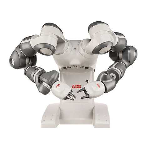
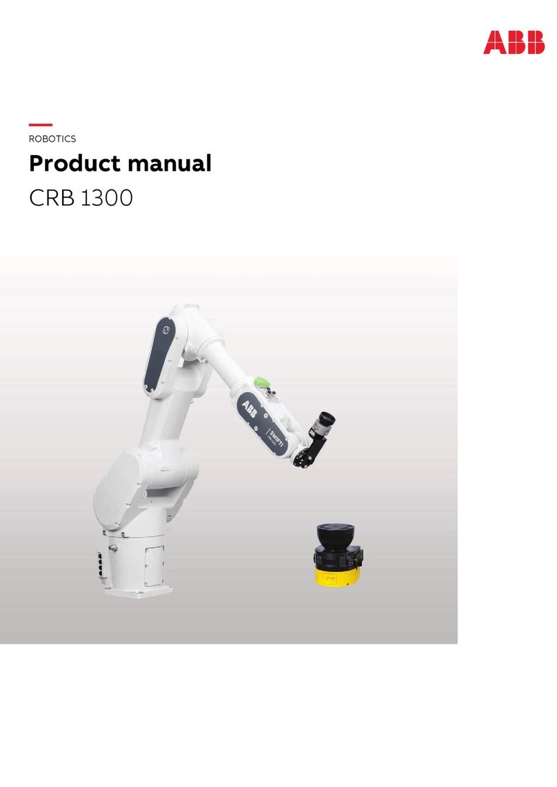
ABB IRB 14000 User manual

ROBOTICS
Product manual
IRB 14000

Trace back information:
Workspace 21B version a6
Checked in 2021-05-31
Skribenta version 5.4.005

Product manual
IRB 14000-0.5/0.5
IRC5
Document ID: 3HAC052983-001
Revision: P
© Copyright 2015 - 2021 ABB. All rights reserved.
Specifications subject to change without notice.

The information in this manual is subject to change without notice and should not
be construed as a commitment by ABB. ABB assumes no responsibility for any errors
that may appear in this manual.
Except as may be expressly stated anywhere in this manual, nothing herein shall be
construed as any kind of guarantee or warranty by ABB for losses, damage to persons
or property, fitness for a specific purpose or the like.
In no event shall ABB be liable for incidental or consequential damages arising from
use of this manual and products described herein.
This manual and parts thereof must not be reproduced or copied without ABB's
written permission.
Keep for future reference.
Additional copies of this manual may be obtained from ABB.
Original instructions.
© Copyright 2015 - 2021 ABB. All rights reserved.
Specifications subject to change without notice.

Table of contents
9Overview of this manual ...................................................................................................................
14Product documentation ....................................................................................................................
16How to read the product manual ......................................................................................................
17Network security ...............................................................................................................................
191 Safety
191.1 Safety information .............................................................................................
191.1.1 Limitation of liability .................................................................................
201.1.2 Safety data .............................................................................................
221.1.3 Requirements on personnel ......................................................................
231.2 Safety signals and symbols .................................................................................
231.2.1 Safety signals in the manual ......................................................................
251.2.2 Safety symbols on manipulator labels .........................................................
311.2.3 Safety symbols on controller labels ............................................................
341.3 Robot stopping functions ....................................................................................
341.3.1 Protective stop and emergency stop ...........................................................
361.4 Installation and commissioning ............................................................................
401.5 Operation ........................................................................................................
401.5.1 Manually stopping or overriding the arm ......................................................
411.5.2 Unexpected movement of robot arm ...........................................................
421.6 Maintenance and repair ......................................................................................
421.6.1 Maintenance and repair ............................................................................
441.6.2 Emergency release of the robot axes ..........................................................
451.6.3 Brake testing ..........................................................................................
461.7 Troubleshooting ................................................................................................
471.8 Decommissioning ..............................................................................................
492 Installation and commissioning
492.1 Introduction to installation and commissioning .......................................................
502.2 Unpacking .......................................................................................................
502.2.1 Pre-installation procedure .........................................................................
542.2.2 Dimensions ............................................................................................
562.2.3 Working range ........................................................................................
592.2.4 Risk of tipping/stability .............................................................................
602.2.5 The unit is sensitive to ESD .......................................................................
612.3 On-site installation ............................................................................................
612.3.1 Lifting the robot with lifting accessories .......................................................
652.3.2 Lifting the robot without lifting accessories ...................................................
672.3.3 Orienting and securing the robot ................................................................
702.3.4 Manually releasing the brakes ...................................................................
722.3.5 Installing the signal lamp ..........................................................................
782.3.6 Electrical connections ..............................................................................
782.3.6.1 Robot cabling and connection points ...............................................
792.3.7 Risk of mechanical damage ......................................................................
802.3.8 Lead-through ..........................................................................................
822.3.9 Installation of ABB grippers .......................................................................
832.4 Controller ........................................................................................................
832.4.1 Overview ...............................................................................................
862.4.2 Connections ...........................................................................................
862.4.2.1 Connecting power and the FlexPendant ...........................................
882.4.2.2 Connecting a PC and Ethernet based options ...................................
932.4.2.3 Connecting I/O signals .................................................................
952.4.2.4 Connecting fieldbuses ..................................................................
982.4.2.5 Connecting safety signals .............................................................
1032.4.3 I/O system .............................................................................................
1032.4.3.1 Local I/O devices .........................................................................
Product manual - IRB 14000 5
3HAC052983-001 Revision: P
© Copyright 2015 - 2021 ABB. All rights reserved.
Table of contents

1052.4.3.2 Conveyor tracking module .............................................................
1072.4.4 Memory functions ....................................................................................
1072.4.4.1 SD-card memory .........................................................................
1082.4.4.2 Connecting an USB memory ..........................................................
1092.4.5 Installation of add-ons ..............................................................................
1092.4.5.1 Installation of Local I/O devices ......................................................
1122.4.5.2 Installation of conveyor tracking module ..........................................
1142.4.6 What is Cartesian speed supervision? .........................................................
1152.5 Start of robot in cold environments ......................................................................
1162.6 Additional information for IRB 14000 .....................................................................
1173 Maintenance
1173.1 Introduction ......................................................................................................
1183.2 Maintenance schedule .......................................................................................
1183.2.1 Specification of maintenance intervals ........................................................
1193.2.2 Maintenance schedule .............................................................................
1213.3 Inspection activities ...........................................................................................
1213.3.1 Inspecting the information labels ................................................................
1253.3.2 Inspecting, signal lamp .............................................................................
1273.3.3 Inspecting, cable harness .........................................................................
1293.3.4 Inspecting, plastic and padding ..................................................................
1313.4 Replacement/changing activities ..........................................................................
1313.4.1 Replacing the battery pack ........................................................................
1363.5 Cleaning activities .............................................................................................
1363.5.1 Cleaning the IRB 14000 ............................................................................
1374 Repair
1374.1 Introduction ......................................................................................................
1384.2 General procedures ...........................................................................................
1384.2.1 Mounting instructions for sealings ..............................................................
1414.3 Arm and arm covers ..........................................................................................
1414.3.1 Replacing the complete arm .....................................................................
1564.3.2 Replacing the encapsulation and covers .....................................................
1594.4 Motors ............................................................................................................
1594.4.1 Replacing the axis-1 motor .......................................................................
1604.4.2 Replacing the axis-2 motor .......................................................................
1834.4.3 Replacing the axis-7 motor .......................................................................
1844.4.4 Replacing the axis-3 motor .......................................................................
1984.4.5 Replacing the axis-4 motor .......................................................................
2164.4.6 Replacing the axis-5 motor .......................................................................
2314.4.7 Replacing the axis-6 motor .......................................................................
2484.5 Mechanical stops ..............................................................................................
2484.5.1 Replacing the axis-1 mechanical stop .........................................................
2594.5.2 Replacing the axis-2 mechanical stop .........................................................
2674.5.3 Replacing the axis-7 mechanical stop .........................................................
2724.5.4 Replacing the axis-3 mechanical stop .........................................................
2804.6 Controller ........................................................................................................
2804.6.1 Replacing the computer ............................................................................
2884.6.2 Replacing the controller fan .......................................................................
2924.6.3 Replacing the capacitor bank ....................................................................
2994.6.4 Replacing the power supply ......................................................................
3034.6.5 Replacing the power distribution board .......................................................
3104.6.6 Replacing the external power distribution board ............................................
3164.6.7 Replacing the axis computer .....................................................................
3234.6.8 Replacing the left arm's drive board ............................................................
3334.6.9 Replacing the right arm's drive board ..........................................................
3414.6.10 Replacing the I/O board ............................................................................
3454.6.11 Replacing the SMB boards ........................................................................
3514.6.12 Replacing the EtherNet switch ...................................................................
6 Product manual - IRB 14000
3HAC052983-001 Revision: P
© Copyright 2015 - 2021 ABB. All rights reserved.
Table of contents
3554.6.13 Replacing the mass memory card ..............................................................
3584.6.14 Replacing the expansion board complete ....................................................
3714.6.15 Replacing the DeviceNet master ................................................................
3824.6.16 Replacing the fieldbus adapter ...................................................................
3874.7 Brake release harness .......................................................................................
3874.7.1 Replacing the brake release harness ..........................................................
3955 Calibration
3955.1 Introduction ......................................................................................................
3965.2 Calibration method ............................................................................................
3985.3 Calibration scale and correct axis position .............................................................
3995.4 Calibrating the robot ..........................................................................................
4075.5 Calibrating the robot for Absolute Accuracy ...........................................................
4115.6 Updating revolution counters ...............................................................................
4175.7 Calibration movement directions for all axes ..........................................................
4185.8 Verifying the calibration position ..........................................................................
4196 Robot description
4196.1 Robot type description .......................................................................................
4237 Decommissioning
4237.1 Introduction ......................................................................................................
4247.2 Environmental information ..................................................................................
4267.3 Scrapping of robot .............................................................................................
4278 Reference information
4278.1 Introduction ......................................................................................................
4288.2 Applicable standards .........................................................................................
4318.3 Unit conversion .................................................................................................
4328.4 Specification of screws .......................................................................................
4348.5 Screw joints ....................................................................................................
4358.6 Weight specifications .........................................................................................
4368.7 Standard toolkit ................................................................................................
4378.8 Special tools ....................................................................................................
4388.9 Lifting accessories and lifting instructions ..............................................................
439Index
Product manual - IRB 14000 7
3HAC052983-001 Revision: P
© Copyright 2015 - 2021 ABB. All rights reserved.
Table of contents
This page is intentionally left blank

Overview of this manual
About this manual
This manual contains instructions for:
• mechanical and electrical installation of the robot
• maintenance of the robot
• mechanical and electrical repair of the robot.
Usage
This manual should be used during:
• installation, from lifting the robot to its work site and securing it to the
foundation, to making it ready for operation
• maintenance work
• repair work and calibration.
Who should read this manual?
This manual is intended for:
• installation personnel
• maintenance personnel
• repair personnel.
Prerequisites
A maintenance/repair/installation personnel working with an ABB Robot must:
• be trained by ABB and have the required knowledge of mechanical and
electrical installation/repair/maintenance work.
Product manual scope
The manual covers covers all variants and designs of the IRB 14000. Some variants
and designs may have been removed from the business offer and are no longer
available for purchase.
Organization of chapters
The manual is organized in the following chapters:
ContentsChapter
Safety information that must be read through before performing
any installation or service work on robot. Contains general safety
aspects as well as more specific information on how to avoid
personal injuries and damage to the product.
Safety, service
Required information about lifting and installation of the robot.Installation and commis-
sioning
Step-by-step procedures that describe how to perform mainten-
ance of the robot. Based on a maintenance schedule that may
be used to plan periodical maintenance.
Maintenance
Step-by-step procedures that describe how to perform repair
activities of the robot. Based on available spare parts.
Repair
Continues on next page
Product manual - IRB 14000 9
3HAC052983-001 Revision: P
© Copyright 2015 - 2021 ABB. All rights reserved.
Overview of this manual

ContentsChapter
Procedures that do not require specific calibration equipment.
General information about calibration.
Calibration information
Environmental information about the robot and its components.Decommissioning
Useful information when performing installation, maintenance
or repair work. Includes lists of necessary tools, additional doc-
uments, safety standards, etc.
Reference information
References
Documentation referred to in the manual, is listed in the table below.
Document IDDocument name
3HAC052984-001Product manual, spare parts - IRB 14000
3HAC052982-001Product specification - IRB 14000
3HAC054949-001Product manual - Grippers for IRB 14000
3HAC052986-001Operating manual - IRB 14000
3HAC050778-003Circuit diagram - IRB 14000
3HAC031045-001Safety manual for robot - Manipulator and IRC5 or OmniCore con-
troller i
3HAC042927-001Technical reference manual - Lubrication in gearboxes
3HAC021313-001Product manual - IRC5
3HAC050948-001Technical reference manual - System parameters
3HAC059109-001Application manual - Scalable I/O
3HAC050991-001Application manual - Conveyor tracking
iThis manual contains all safety instructions from the product manuals for the manipulators and the
controllers.
Revisions
DescriptionRevision
First edition.-
The following updates are done in this revision:
• Minor editorial changes.
• Changed article number for the ESD warning label and added
AbsAcc label, see Inspecting the information labels on page 121.
•Added figures for axis-4, axis-5 and axis-6 motors for removal and
refitting of the wave generator.
• Added reference to absolute accuracy calibration for some repair
procedures.
A
Continues on next page
10 Product manual - IRB 14000
3HAC052983-001 Revision: P
© Copyright 2015 - 2021 ABB. All rights reserved.
Overview of this manual
Continued

DescriptionRevision
The following updates are done in this revision:
• Changed tightening torque of axis-7 motor from 0.2 Nm to 0.8 Nm.
• Added a tightening torque for the axis-7 cable bracket (0.8 Nm).
•Corrected orientation of removal tool on motor in figure that shows
fitting of the removal tool on the axis-1 motor.
• Corrected the procedure for replacing the axis-6 motor by adding
steps for removal of two more covers/padding added.
• Corrected figure of the axis-3 motor to show orientation of motor
according to motor connector location.
• Corrected the procedure for replacing the battery pack by adding
step for removal of two more screws on the body cover.
• Added a caution signal to be careful not to hit the arms into
something while lifting and transporting the robot.
• Changed procedure for replacing the field bus adapter. The com-
puter cover does not need to be removed.
•Added a step for moving the battery packs from the old drive board
onto the new.
• Added information about deviations and fulfilment of certain re-
quirements for ISO10218-1:2011, see Applicable standards on
page 428.
• Added safety information for collaborative robots.
• Changed torque y and torque z for endurance load and maximum
load.
•Added information about setting the running speed to 100% before
running fine calibration procedure.
B
The following updates are done in this revision:
• Figures in procedures about Fitting the wave generator to the
motor are updated.
• Grease name and volume is moved to Manual Lubrication in
gearboxes.
•Specification of screws added to section "Reference information".
• Screw/nut type and tightening torque added to steps in section
"Repair".
• Plastic parts are ESD coated; names and spare part numbers are
modified.
• ABB-supplied main power cables in different interface standards
are provided as options. See Main power cable on page 78.
• Applicable ESD-standards added.
• Information added about checking PTFE film before refitting the
axis-5 and axis-6 motors, see Replacing the axis-5 motor on
page 216 and Replacing the axis-6 motor on page 231.
C
Published in release R16.2. The following updates are made in this revi-
sion:
• Sections about Replacing axis-1 and axis-7 motor revised.
• Safety section about pressure relief valves added.
• RT6 safety relay supported and related information added. See
Safety relay (option 1526-X) on page 100.
• Max current added for pin 9 on connector XS7 and XS8.
• Added line fusing, rated power, and required equipment informa-
tion for power connection to the controller. See Connecting power
supply on page 86.
• Re-calibration instruction for replacing hall sensors revised.
D
Continues on next page
Product manual - IRB 14000 11
3HAC052983-001 Revision: P
© Copyright 2015 - 2021 ABB. All rights reserved.
Overview of this manual
Continued

DescriptionRevision
Published in release R17.1. The following updates are made in this revi-
sion:
• DSQC1000 computer changed to DSQC1018 computer.
• Re-calibration instruction for replacing hall sensors revised.
• The hall sensor must be replaced if the robot is rebuilt.
• Added note about fine calibration, see Calibrating the robot on
page 399.
E
Published in release R17.2. The following updates are made in this revi-
sion:
• Information about minimum resonance frequency added.
• Bending radius for floor cables added.
• Updated list of applicable standards.
• Section Start of robot in cold environments on page 115 added.
• Added information about service routine YuMi AbsAcc Recovery
in Calibration chapter.
• Specified the view of the hole configuration on base.
• Updated the value of air supply on controller interface.
F
Published in release R18.1. The following updates are made in this revi-
sion:
• Safety section restructured.
• Clarified the limitations for Isolated Lan 3 in the section Isolated
LAN 3 or LAN 3 as part of the private network (only for RobotWare
6.01 and later) on page 91.
• Information about myABB Business Portal added.
G
Published in release R18.2. The following updates are made in this revi-
sion:
• Minor additions in the information regarding the service routine
YuMi AbsAcc Recovery.
• New article number for the YuMi AbsAcc Recovery tool, now
complete kit with tool box.
• Updated cleaning method.
• Updated the figure of the hole configuration on base.
•Removed hall sensor replacement procedure because hall sensors
are not spare parts any more.
• Updated spare part note to axis-5 and -6 motors.
H
Published in release R18.2. The following updates are made in this revi-
sion:
• Updated references.
J
Published in release 19B. The following updates are made in this revision:
• Updated the shipping and transportation position.
• Added information about the center of gravity (COG).
• Updated precautions for the robot working in contact with the
operator.
• New chapters added: Conveyor tracking module on page 105 and
Installation of conveyor tracking module on page 112.
•New chapters added: Local I/O devices on page 103 and Installation
of Local I/O devices on page 109.
K
Published in release 20A. The following updates are made in this revision:
• Added information about Type A which has a reinforced design.
•Clarified and added information in mounting instructions for rotat-
ing sealings, see Mounting instructions for sealings on page 138.
L
Continues on next page
12 Product manual - IRB 14000
3HAC052983-001 Revision: P
© Copyright 2015 - 2021 ABB. All rights reserved.
Overview of this manual
Continued

DescriptionRevision
Published in release 20B. The following updates are made in this revision:
• Updated robot arm dimension.
• Updated safety relay information because SSR10M safety relay
replaces RT6 safety relay.
• Information regarding multiple EtherNet based options removed
from section "Connecting a PC and Ethernet based options".
M
Published in release 20D. The following updates are made in this revision:
• Updated figure showing the connectors on the interface on the
left side panel of the controller.
• Added software version requirement for selecting arm configura-
tion of Type A during system installation.
N
Published in release 21B. The following updates are made in this revision:
• Information added about China RoHS, see Environmental inform-
ation on page 424.
• Added information about joint torques, see Joint torques on
page 53.
• Text regarding diameter of air hoses is updated, see Controller
interface, left side on page 84.
• Added delivery information about the attachment screws, see
Specification, attachment screws and pins on page 68.
P
Product manual - IRB 14000 13
3HAC052983-001 Revision: P
© Copyright 2015 - 2021 ABB. All rights reserved.
Overview of this manual
Continued

Product documentation
Categories for user documentation from ABB Robotics
The user documentation from ABB Robotics is divided into a number of categories.
This listing is based on the type of information in the documents, regardless of
whether the products are standard or optional.
Tip
All documents can be found via myABB Business Portal, www.abb.com/myABB.
Product manuals
Manipulators, controllers, DressPack/SpotPack, and most other hardware is
delivered with a Product manual that generally contains:
• Safety information.
• Installation and commissioning (descriptions of mechanical installation or
electrical connections).
•Maintenance (descriptions of all required preventive maintenance procedures
including intervals and expected life time of parts).
• Repair (descriptions of all recommended repair procedures including spare
parts).
• Calibration.
• Decommissioning.
•Reference information (safety standards, unit conversions, screw joints, lists
of tools).
• Spare parts list with corresponding figures (or references to separate spare
parts lists).
• References to circuit diagrams.
Technical reference manuals
The technical reference manuals describe reference information for robotics
products, for example lubrication, the RAPID language, and system parameters.
Application manuals
Specific applications (for example software or hardware options) are described in
Application manuals. An application manual can describe one or several
applications.
An application manual generally contains information about:
• The purpose of the application (what it does and when it is useful).
•What is included (for example cables, I/O boards, RAPID instructions, system
parameters, software).
• How to install included or required hardware.
• How to use the application.
• Examples of how to use the application.
Continues on next page
14 Product manual - IRB 14000
3HAC052983-001 Revision: P
© Copyright 2015 - 2021 ABB. All rights reserved.
Product documentation

Operating manuals
The operating manuals describe hands-on handling of the products. The manuals
are aimed at those having first-hand operational contact with the product, that is
production cell operators, programmers, and troubleshooters.
Product manual - IRB 14000 15
3HAC052983-001 Revision: P
© Copyright 2015 - 2021 ABB. All rights reserved.
Product documentation
Continued

How to read the product manual
Reading the procedures
The procedures contain all information required for the installation or service activity
and can be printed out separately when needed for a certain service procedure.
Safety information
The manual includes a separate safety chapter that must be read through before
proceeding with any service or installation procedures. All procedures also include
specific safety information when dangerous steps are to be performed.
Read more in the chapter Safety on page 19.
Illustrations
The product is illustrated with general figures that does not take painting or
protection type in consideration.
Likewise, certain work methods or general information that is valid for several
product models, can be illustrated with illustrations that show a different product
model than the one that is described in the current manual.
16 Product manual - IRB 14000
3HAC052983-001 Revision: P
© Copyright 2015 - 2021 ABB. All rights reserved.
How to read the product manual

Network security
Network security
This product is designed to be connected to and to communicate information and
data via a network interface. It is your sole responsibility to provide, and
continuously ensure, a secure connection between the product and to your network
or any other network (as the case may be).
You shall establish and maintain any appropriate measures (such as, but not limited
to, the installation of firewalls, application of authentication measures, encryption
of data, installation of anti-virus programs, etc) to protect the product, the network,
its system and the interface against any kind of security breaches, unauthorized
access, interference, intrusion, leakage and/or theft of data or information. ABB
Ltd and its entities are not liable for damage and/or loss related to such security
breaches, any unauthorized access, interference, intrusion, leakage and/or theft
of data or information.
Product manual - IRB 14000 17
3HAC052983-001 Revision: P
© Copyright 2015 - 2021 ABB. All rights reserved.
Network security

This page is intentionally left blank

1 Safety
1.1 Safety information
1.1.1 Limitation of liability
Limitation of liability
Any information given in this manual regarding safety must not be construed as a
warranty by ABB that the industrial robot will not cause injury or damage even if
all safety instructions are complied with.
The information does not cover how to design, install and operate a robot system,
nor does it cover all peripheral equipment that can influence the safety of the robot
system.
In particular, liability cannot be accepted if injury or damage has been caused for
any of the following reasons:
• Use of the robot in other ways than intended.
• Incorrect operation or maintenance.
• Operation of the robot when the safety devices are defective, not in their
intended location or in any other way not working.
• When instructions for operation and maintenance are not followed.
• Non-authorized design modifications of the robot.
• Repairs on the robot and its spare parts carried out by in-experienced or
non-qualified personnel.
• Foreign objects.
• Force majeure.
Spare parts and equipment
ABB supplies original spare parts and equipment which have been tested and
approved. The installation and/or use of non-original spare parts and equipment
can negatively affect the safety, function, performance, and structural properties
of the robot. ABB is not liable for damages caused by the use of non-original spare
parts and equipment.
Product manual - IRB 14000 19
3HAC052983-001 Revision: P
© Copyright 2015 - 2021 ABB. All rights reserved.
1 Safety
1.1.1 Limitation of liability

1.1.2 Safety data
About this section
This chapter describes the necessary safety data required by standard EN ISO
13849-1:2015.
Prevailing directives and standards
For the use of industrial robots and how to protect personnel from being injured,
special regulations must be fulfilled as described in the following directives and
standards:
• Machinery Directive 2006/42/EC
• EN ISO 10218-1:2011
• EN ISO 13849-1:2008 (when explicitly called forth by EN ISO 10218-1:2011
as ISO 13849-1:2006)
• EN ISO 13849-1:2015
Performance level and category
EN ISO 13849-1, which is a B-standard, describes the general concept of
performance level (PL) and category. Each machine or machinery is potentially
dangerous and can cause personal injury. Based on severity of injury and probability
of accident, when using the machine, a certain level of safety performance, so
called required performance level (PLr) can be defined, where level a represents
the lowest risk and level e the highest. According to this, the machine must be
equipped with safety related parts, meeting the required performance level, to
reduce the risk to accepted low level. As specified in EN ISO 10218-1, normally
PL d is required for robots, but depending on the applications a higher requirement
could be needed if a risk analysis will result in PL e.
To comply with a certain PLr, in this case d, the safety related parts of the robots
and controllers must be structurally designed according to specific structure
categories and using reliable components.
In EN ISO 13849-1 it is in detail specified what category and components data,
which must be met, to fulfill PL d. These are:
• Category 3, which is normally fulfilled using double channels
• MTTFD(Mean Time To dangerous Failure) – high
• DC (Diagnostic Coverage) – low or medium
• CCF (Common Cause Failures) – better than 65 scores according to Annex
F
Performance level for ABB IRC5 controller
To verify that robots and controller comply with at least PL d a self assessment
has been carried out and documented in a Technical Report. The essential
conclusions are accounted for below.
The safety related parts of robot and controller are e.g. the following stop circuits:
• Enabling device
• Emergency stop on operator panel
Continues on next page
20 Product manual - IRB 14000
3HAC052983-001 Revision: P
© Copyright 2015 - 2021 ABB. All rights reserved.
1 Safety
1.1.2 Safety data
Other manuals for IRB 14000
3
Table of contents

Other ABB Robotics manuals

ABB
ABB M2004 User instructions

ABB
ABB Fronius TPS 320i Instructions for use

ABB
ABB IRC5 Compact User manual

ABB
ABB IRB 8700 Series Guide

ABB
ABB MultiMove Instructions for use

ABB
ABB IRB 1010 User manual

ABB
ABB IRB 6640 - 180/2.55 User manual

ABB
ABB IRB 1400 User manual

ABB
ABB IRB 6400R User manual

ABB
ABB OmniCore V400XT User manual