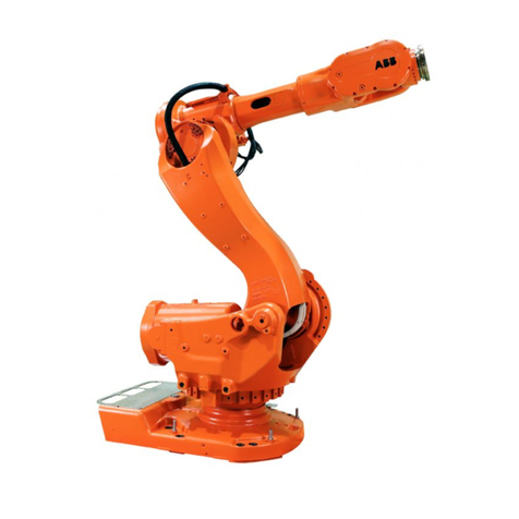
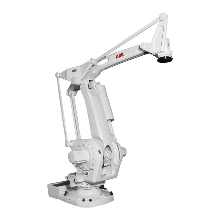
ABB IRB 640 User manual

Product Manual
3HAC 7579-1
IRB 640
M2000

The information in this document is subject to change without notice and should not be construed as a
commitment by ABB Robotics Products AB. ABB Robotics Products AB assumes no responsibility for
any errors that may appear in this document.
In no event shall ABB Robotics Products AB be liable for incidental or consequential damages arising
from use of this document or of the software and hardware described in this document.
This document and parts thereof must not be reproduced or copied without
ABB Robotics Products AB´s written permission, and contents thereof must not be imparted to a third
party nor be used for any unauthorized purpose. Contravention will be prosecuted.
Additional copies of this document may be obtained from ABB Robotics Products AB at its then current
charge.
© ABB Robotics Products AB
Article number: 3HAC 7677-1
Issue: M2000/Rev.1
ABB Robotics Products AB
S-721 68 Västerås
Sweden

Installation and Commissioning
CONTENTS Page
Product Manual IRB 640 1
1 Transporting and Unpacking......................................................................................... 3
1.1 Stability / risk of tipping......................................................................................... 4
1.2 System diskettes ..................................................................................................... 4
2 On-Site Installation.........................................................................................................5
2.1 Lifting the manipulator........................................................................................... 5
2.2 Assembling the robot.............................................................................................. 9
2.2.1 Manipulator.................................................................................................. 9
2.3 Stress forces............................................................................................................ 10
2.3.1 Stiffness........................................................................................................ 10
2.3.2 All versions.................................................................................................. 10
2.4 Amount of space required....................................................................................... 11
2.4.1 Manipulator.................................................................................................. 11
2.5 Manually engaging the brakes................................................................................ 12
2.6 Restricting the working space................................................................................. 13
2.6.1 Axis 1........................................................................................................... 13
2.6.2 Axes 2 and 3................................................................................................. 14
2.7 Mounting holes for equipment on the manipulator................................................ 15
2.7.1 Quality of screws for fitting extra equipment.............................................. 15
2.8 Loads ......................................................................................................................16
3 Customer connections on manipulator ......................................................................... 19
3.1 Connection of extra equipment to the manipulator................................................ 23
3.1.1 Connections on upper arm. .......................................................................... 23
3.1.2 Connections on upper arm with CanBus...................................................... 24
3.1.3 Connection of signal lamp on upper arm (option)....................................... 25

Installation and Commissioning
Page
2 Product Manual IRB 640

Installation and Commissioning Transporting and Unpacking
Product Manual IRB 640 3
1 Transporting and Unpacking
NB:
Before starting to unpack and install the robot, read the safety regulations and
other instructions very carefully. These are found in separate sections in the
User’s Guide and Product manual.
The installation shall be made by qualified installation personnel and should con-
form to all national and local codes.
When you have unpacked the robot, check that it has not been damaged during
transport or while unpacking.
Operating conditions:
Ambient temperature + 5° to + 45°C (manipulator)
Relative humidity Max. 95% at constant temperature
Storage conditions:
If the equipment is not going to be installed straight away, it must be stored in a dry
area at an ambient temperature between -25°C and +55°C.
When air transport is used, the robot must be located in a pressure-equalized area.
The net weight of the manipulator is approximately 1950 kg.
The control system weighs approximately 240 kg.
Whenever the manipulator is transported, axis 2 must be bent backwards 30° and
axis 3 must be moved down to a position against the rubber stops on axis 2.

Transporting and Unpacking Installation and Commissioning
4 Product Manual IRB 640
1.1 Stability / risk of tipping
Whenthemanipulatoris notfastenedtothefloorandstandingstill,themanipulator
is not stable in the whole working area. When the arms are moved, care must be
taken so that the centre of gravity is not displaced, as this could cause the manipula-
tor to tip over.
The following table shows the positions where there is a risk of tipping and refers to fig-
ures in chapter 3.8 in Product Specification IRB 640, for definition of position 0 and 5.
no = stable
yes = risk of tipping
1.2 System diskettes
The diskettes in the box, fixed to the shelf for the teach pendant, should be copied
(in a PC) before they are used. Never work with the original diskettes. When you have
made copies, store the originals in a safe place.
Do not store diskettes inside the controller due to the high temperatures there.
Working area, position 0
load = 0 kg load = max Working area, position 5
load = 0 kg load = max
no no no yes

Installation and Commissioning On-Site Installation
Product Manual IRB 640 5
2 On-Site Installation
2.1 Lifting the manipulator
The following lifting instructions are valid for a “naked”robot. Whenever
additional equipment is put on the robot, the centre of gravity can change and
make lifting dangerous.
Never walk under a suspended load.
If the integrated lifting ears on the front cannot be reached, the manipulator must be
reoriented to the sync position.
The best way to lift the manipulator is to use lifting straps and a traverse crane.
Attach the straps to the integrated lifting eyes on both sides of the frame (see
Figure 2). The lifting strap dimensions must comply with the applicable standards
for lifting. It is also possible to use two lifting devices (option) for use with a fork
lift truck (see Figure 4).
NB!
The right lifting device, the robot seen from behind, must be removed before
start-up, see Figure 1.
Figure 1 Lifting device that must be removed.
View from behind
Lifting device

On-Site Installation Installation and Commissioning
6 Product Manual IRB 640
Figure 2 Lifting the manipulator using a traverse crane.
Length=1150 Length=950
Crane lift
240
700

Installation and Commissioning On-Site Installation
Product Manual IRB 640 7
Figure 3 Lifting the manipulator with the arm system in the calibration position.
Crane lift, in calibration position
Length=1150 Length=950

On-Site Installation Installation and Commissioning
8 Product Manual IRB 640
Figure 4 Lifting the manipulator using a fork lift truck.
Crane lifting is not permitted using the fork lift arrangement.
Fork lift
1120
400

Installation and Commissioning On-Site Installation
Product Manual IRB 640 9
2.2 Assembling the robot
2.2.1 Manipulator
The three support points of the manipulator foot shall be mounted on three flat surfaces
with a flatness within the specification. Use shims if necessary. The rest of the surface
must be flat within ± 2 mm. Footprint diagram, see Figure 5. Floor mounted models
can be tilted max. 5o.
The levelness requirement for the surface is as follows:
Figure 5 Bolting down the manipulator (dimensions in mm).
The manipulator is fixed with three M30 bolts, tightened alternately.
Suitable bolts: M30x160 8.8 Socket screw with washer
Tightening torque: 1000 Nm
Two guide sleeves can be added to twoof the bolt holes, to allow the same manipulator
to be re-mounted without program adjustment (see Figure 5).
When bolting a mounting plate or frame to a concrete floor, follow the general
instructions for expansion-shell bolts. The screw joint must be able to withstand the
stress loads defined in Chapter 2.3 Stress forces .
0.5
D=64 H9 (3x)
Support surface D=85 (3x)
A
0.2 720
480±0.1
A
∅
415.7
D=32(3x)
D=48(3x)
A - A
X
Y
Z100 ±0,5
15+2
0
Guide sleeve

On-Site Installation Installation and Commissioning
10 Product Manual IRB 640
2.3 Stress forces
2.3.1 Stiffness
The stiffness of the foundation must be designed to minimize the influence on the
dynamic behaviour of the robot. For optimal performance the frequency of the founda-
tion with the robot weight must be higher than 22 Hz.
TuneServo can be used for adapting the robot tuning to a non-optimal foundation.
2.3.2 All versions
Endurance load Max. load
(In operation) (Emergency stop)
Force xy ±12 000 N ±18 000 N
Force z 21 000 ±5 500 N 21 000 ±10000 N
Torque xy ± 32 000 Nm ±39 000 Nm
Torque z ±6 000 Nm ±13 000 Nm
Force xy and torque xy are vectors that can have any direction in the xy plane.
Figure 6 The directions of the stress forces.
YX
Z

Installation and Commissioning On-Site Installation
Product Manual IRB 640 11
2.4 Amount of space required
The amount of working space required to operate the manipulator and controller is
illustrated in Figure 7.
The working range for axis 1 is +/- 180°.
NB: There are no software or mechanical limits for the working space under the
base of the manipulator.
2.4.1 Manipulator
Figure 7 The working space required for the manipulator.
IRB 640
All dimensions refer to TCP 0 (mm)
+1
-1
1220 2905
+2-2
+3
-3
2/3
+6
-6
TCP 0 2310
599

On-Site Installation Installation and Commissioning
12 Product Manual IRB 640
2.5 Manually engaging the brakes
All axes come equipped with holding brakes. When the position of a manipulator axis
needs to be changed without connecting the controller, an external voltage supply
(24 V DC) must be connected to enable engagement of the brakes. The voltage supply
should be connected to the connector at the base of the manipulator (see Figure 8).
Figure 8 Connection of external voltage to enable engagement of the brakes.
External power must be connected according to Figure 8. Incorrectly connected
power can release all brakes, causing simultaneously movement of all axes.
When the controller or the voltage deviceis connected, illustrated above,the brakescan
be engaged separately by means of the push-buttons on the brake release unit on the
exterior of the axis 3 gear box. The push-buttons are marked with the appropriate axis
name. The names of the axes and their motion patterns are illustrated in Figure 9.
WARNING: Be very careful when engaging the brakes. The axes become acti-
vated very quickly and may cause damage or injury.
Figure 9 The robot axes and motion patterns.
0 V B14
+24 V B16
Brake release unit
1
6
5
4
3
2
Axis 3
Axis 2
Axis 1
Axis 6
NB!
Buttons 4 and 5
are not connected.

Installation and Commissioning On-Site Installation
Product Manual IRB 640 13
2.6 Restricting the working space
When installing the manipulator, make sure that it can move freely within its entire
working space. If there is a risk that it may collide with other objects, its working space
should be limited, both mechanically and using software. Installation of an optional
extra stop for the main axes 1, 2 and 3 is described below.
Limiting the working space using software is described in the chapter System Param-
eters in the User’s Guide.
2.6.1 Axis 1
The range of rotation for axis 1 can be limited mechanically by fitting extra mechanical
stop arms.
Instructions for doing this are supplied with the kit.
IMPORTANT! The mechanical stop pin and the extra moveable mechanical stop
arm for axis 1 must absolutely be replaced after a hard collision, if the pin or arm
has been deformed.

On-Site Installation Installation and Commissioning
14 Product Manual IRB 640
2.6.2 Axes 2 and 3
The working range of axes 2 and 3 is limited by mechanical stops and can be reduced
by adding fixed mechanical stops.
The stops are mounted on the inside of the frame to each axis.
Extra stops must be mounted in a row, starting at the fixed stop.
Figure 10 Mechanically limiting axes 2 and 3.
NB!
The robot is always delivered with one extra mechanical stop mounted for axis 3.
It is not allowed to remove it.
Holes for extra stops

Installation and Commissioning On-Site Installation
Product Manual IRB 640 15
2.7 Mounting holes for equipment on the manipulator
NB: Never drill a hole in the manipulator without first consulting maintenance
staff or the design department at ABB Flexible Automation.
Figure 11 Holes for mounting extra equipment (dimensions in mm).
Figure 12 The mechanical interface (mounting flange) ISO 9409 (dimensions in mm).
2.7.1 Quality of screws for fitting extra equipment
When fitting tools on the manipulator’s mounting flange (see above), use only screws
with quality of 12.9. When fitting other equipment, standard screws with quality 8.8
can be used.
M10 (2x)
200
6069
220
411
486
80
depth 25
99
126
Limit for M10 surfaces
45
M10 (2x) through M10 (4x) through
260
130
230
100
35
30o
60o
D=10 H7 depth 10
M10 (6x) depth 18
D=160 h7
D=80 H7
D=125
8
8
F - F

On-Site Installation Installation and Commissioning
16 Product Manual IRB 640
2.8 Loads
It is important to define the loads properly (with regard to the position of centre of grav-
ity and inertia factor) in order to avoid jolting movements and unnecessary stops due to
overloaded motors.
For more information see chapter 3.4 in Product Specification IRB 640 (Technical
specification) for load diagrams, permitted extra loads (equipment) and their positions.
The loads must also be defined in the software, see User´s Guide.

Installation and Commissioning On-Site Installation
Product Manual IRB 640 17

On-Site Installation Installation and Commissioning
18 Product Manual IRB 640
Table of contents
Other ABB Robotics manuals

ABB
ABB IRB 1200 User manual

ABB
ABB IRB 2600 Series User manual

ABB
ABB IRB 760 Owner's manual

ABB
ABB IRB 1600 - 5/1,2 type A User manual

ABB
ABB IRC5 Compact User guide

ABB
ABB OmniCore V400XT User manual

ABB
ABB IRB 14050 Owner's manual

ABB
ABB OmniCore User manual

ABB
ABB IRB 365 User manual

ABB
ABB IRB6400 Programming manual
Popular Robotics manuals by other brands

Robotronics
Robotronics Toby Tire Robot operating manual

Keyestudio
Keyestudio 4DOF manual

Mitsubishi
Mitsubishi MELFA RH-3FH-D Series Special Specifications Manual

Mover-Technology
Mover-Technology CAMPER TROLLEY 2500 manual

adept technology
adept technology Quattro s650H user guide

IMS ROBOTICS
IMS ROBOTICS DRIVE plus Repair manual