Abbey Machinery VF1500T Guide

Vertical Auger
TUB FEEDER
All Models

2
Abbey Tub Feeder P.D.I Chart
This Dealer pre-delivery inspection chart is to be completed and signed by the dealer or their representative
before the machine is supplied to the customer.
Model______________________Date_________________Serial No_____________________
Tick box below after item is checked.
All Models
Check all hydraulic connections.
Check opening and closing of the door and conveyor operation.
Check all gearbox Oil Levels.
Check wheel studs are torqued correctly, axle bolts and check function of hand brake.
Check play on wheel bearings by rocking the wheels and check tyre pressures (refer to page 7).
Check bolt on hitch bolts after adjusting the hitch to level the machine.
Check all lighting is working correctly.
Check all safety guarding and devices are fitted, and in good working order.
Check all lubrication points and grease.
Check that knifes are fitted securely, KEEP CLEAR OF SHARP EDGES
Check and ensure the right PTO shaft is cut to the correct length (recommended shear-bolt should be
fitted.)
Visually check the driveline and check the conveyor chain tension
Check machine running and vertical auger is rotating smoothly.
Check electronic weighing system is weighing correct weight and customer understands how to work
it.
Check the machine overall visually and that a copy of the instruction manual is being supplied to the
customer with the machine.
Sign below after working through the above check list, and log on to www.abbeymachinery.com dealer
section to register this machine.
N.B. Machine must be registered for warranty purposes.
Signature:_________________________________

3
INSTRUCTION MANUAL CONTENTS
Section No.
Page No.
1.0
The function of the Tub Feeder.
4
2.0
Abbey Tub Feeder Safety warning.
5
3.0
Abbey Tub Feeder setting up for use.
7
4.0
Abbey Tub Feeder operating instructions.
11
5.0
Tub Feeder care and maintenance.
14
5.1
Pre Season Abbey Tub Feeder Maintenance.
23
6.0
Replacement Parts.
24
7.0
Warranty.
53
***IMPORTANT NOTE ***
1. Drawings in this manual are not to scale.
2. While every care is taken to ensure that all information in this manual is correct, the
manufacturer cannot be held responsible for any errors or omissions therein.
3. When ordering parts ensure you have the correct reference number and also the serial
number of the Tub Feeder.

4
MODEL No
Suggested Max
Load Weights
tonnes
TUB FEEDER
SINGLE AUGER MODELS
VF 850
3
VF 950 /VF1000
3.5
VF 1050
4
VF 1250
4.5
VF 1450
4.8
TWIN AUGER MODELS
VF 1500 TWIN
5
VF 1650
6.2
VF 1850
7.2
VF 2100
8.2
VF 2250
9.4
VF 2450
10.2
VF 2650
11
VF 2850
11.8
The above are the recommended max Load weights not to be
exceeded by feeder operators. In many applications these
weights will not be achieved particularly if the feeder is used to
process High dry matter feedstuffs.
The raised top retaining ring offered on feeder models is
intended as an overflow ring for use with high dry matter
material. The raised top retaining ring is not intended and must
not be used to increase machine capacity above the max Load
weights stated.

5
The Range of Abbey Diet Feeders includes
100 CD, 145 GD
The Range of Abbey Vertical Augur Tub Feeders includes
VF Single 750, 800, 1000, 1050, 1250, 1450,
VF Twin 1500, 1650, 1850. 2050. 2250, 2450, 2650, 2850
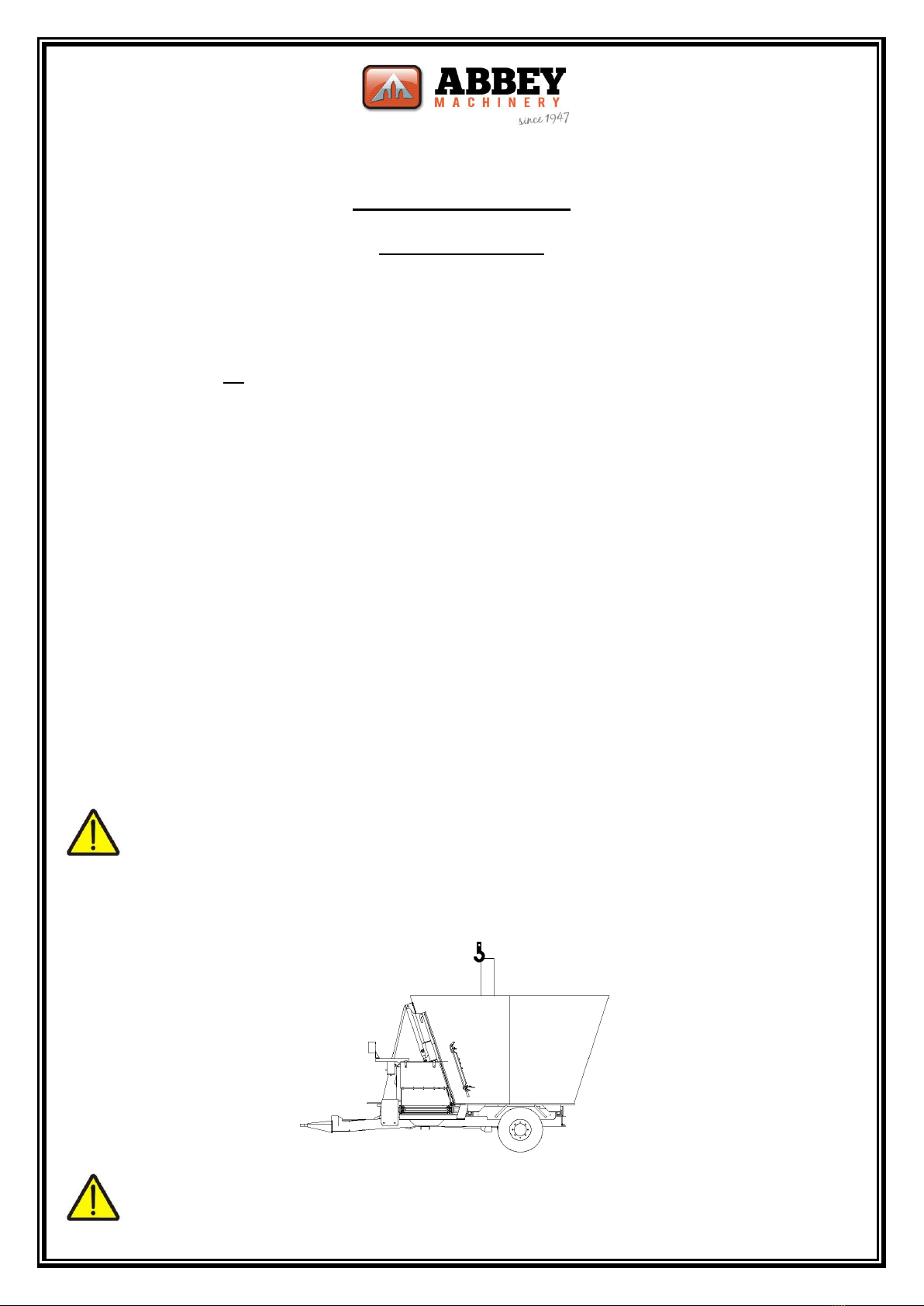
6.0 THE FUNCTION OF THE TUB FEEDER
The Abbey Tub Feeder is a trailed machine which is capable of independently mixing, transporting and feeding
set weights of ingredients to make a complete diet for cattle. It could be also used as a processing unit to
produce rations for other animals (i.e. pigs, sheep, or poultry). The Tub Feeder has been solely designed for
agricultural use, but may in certain circumstances be used to produce mixed rations for other purposes (it
must be noted that the standard Abbey Tub Feeder (unladen) has not been designed to travel at speeds over
25km/h).
The principle of the standard Abbey Tub Feeder is to be loaded with set weights of ingredients which are
mixed as they are loaded into the machine. The Abbey Tub Feeder uses a central vertical auger to chop and
mix the material with the door of the machine closed, and to feed out the material with the door of the
machine open. The ingredients are weighed by the feeder weighing system as they are loaded and unloaded. A
range of functions on the digital scales allows a number of formulae for each ration to be stored.
The feeder can be fitted with one of three systems for feeding out the ration. The standard system is a
conveyor used to transfer the ration to the feed passage. The second optional system is an elevator, and is
used to feed the material into walled troughs or over barriers. The elevator’s height can also be controlled
from the tractor cab and can be set to suit the operator’s needs. The third optional system allows the machine
to be used in blind passages by feeding out through two rear doors. The Abbey Tub Feeder was solely built for
this function and should be operated within the limit of the instruction manual. The above descriptions of the
functions of each Tub Feeder, are provided to show how each Tub Feeder can be used. Further detail on the
Tub Feeder and their variations can be found on the relevant leaflets.
* IMPORTANT *
READ INSTRUCTIONS CAREFULLY BEFORE
OPERATING THIS MACHINE
* The entire manual must be read and understood before operating
this machine, If there is confusion about the safe operation
of any part of the machine, contact your dealer
before operating it.

6
Abbey Tub Feeders
2.0 SAFETY WARNING
1. Always ensure that before operating the machine both the feeder guards and PTO shield are in
place.PTO shields and feeder covers should be properly maintained and must always be replaced
after carrying out adjustments or repairs.
2. Before making adjustments or carrying out any maintenance work it is important that:
(6) The tractor engine is stopped
(ii) The PTO shaft and the hydraulic hoses are disconnected.
3. Operators should not wear loose, flapping clothing when working near PTO driven machinery.
Dangling chains and torn clothing could get caught up in moving parts.
4. Care should be taken while carrying out maintenance inside the feeder, because the barrel of the
feeder can be extremely slippy.
5. Do not distract people who are using machines.
6. Do not leave the feeder loaded overnight.
7. Keep clear of all moving or rotating parts while the machine is operating. Rotating knifes and fodder
(i.e. round bales) inside the machine may cause injury. Keep clear of tub top edge while machine is
working.
8. Always check the machine is in good working order before starting it.
9. Non-standard Abbey parts should not be used on the feeder especially not on the weighing system.
10. Under no circumstances should anyone climb the ladder while the machine is operating or be
transported on the machine ladder.
11. The operator must ensure that all persons are standing clear both of the door and of the conveyor
before starting the machine. They will risk being injured if they come in contact with the machine.
12. The accompanying shaft instruction manual must be consulted before operating or maintaining the
PTO shaft.
13. Standard points on the machine must be used if the Feeder is required to be lifted (drawing A).
Warning:
Standard lifting points if the machine is to be lifted for transport, use the relevant holes located at
the top of the mixing tub
Drawing A: Lifting positions for Diet Feeder
Caution: Four Lifting points most be used.

7
Abbey Tub Feeders
2.0 SAFETY WARNING (cont’d)
14. The PTO shaft of the machine is to be left on the stand provided, when the machine is not in use to
prevent the shaft guard from being damaged.
15. If you have any doubt as to the safe operation or maintenance of your Tub Feeder contact your local
dealer.
16. The operator must work the feeder in a safe manner and must obey the road regulations of that
person’s country
17. Persons unfamiliar with the Tub Feeder must be supervised until the required level of competence is
gained in operating and maintaining the machine safely
18. Care must be taken when operating the hydraulic systems of the feeder. Particular attention must be
given to the safe operation of the conveyor and the machine door.
19. The ladder must only be used as a means of access to the machine only when it is unsafe to enter by
the door of the machine.
20. Extreme care must be taken to prevent touching the sharp edges of the blades in the feeder if you are
required to enter the machine.
21. Do not stand over or above the machine when loading it (e.g. for manual loading). All baled fodder
should be opened on the ground before loading it into the machine. Extreme care should be taken
when loading the feeder manually
22. Never work PTO shafts which are not fully engaged on their mating 6 spline shafts or nor fully
guarded.
23. Never use the Tub Feeder to mix products other than those normally used to feed live stock.
24. Never leave the feeder unattended whilst it is working.
25. The machine should not be transported while it is working or fully loaded at speeds exceeding 8
km/hr. Transporting up to speeds of 25 km/hr should only be done with the machine empty.
Excessive speed may cause a risk of overturning the machine.
26. Extreme care should be taken when operating the Counter Blades in or out. Beware of possible back
lash when gripping the Counter Blade handle, keep thumbs clear.
Diet Feeder Noise Levels
Continuous A-weighted sound level at workstations noise levels exceeds 70 db (a).
Peak C-weighted instantaneous sound pressure exceeds 63 pa.
Caution
The necessary protective devices should be worn when operating the machine.

8
Abbey Tub Feeders
6.0 SETTING UP FOR USE
1. Connect the Tub Feeder to the tractor pick-up hitch or drawbar. If connected to the tractor drawbar
the optional necessary hitch eye reducer bush must be used. Measure the P1’O shaft of the machine
and ensure that it is fitted according to its instructions.
2. Set the hitch eye of the feeder so that the machine is level when hooked to the tractor.
3. Ensure all guards are in place before operating the machine.
4. Connect hydraulic hoses to the tractor. Check that the hydraulic brakes on the machine are working
correctly. Check that all the required functions on the machine are operating correctly. Connect and
check the lights of the machine. Ensure that the digital scale of the machine is functioning correctly
before filling the machine. Also read through and understand the accompanying digital scales manual
before operating the feeder.
5. Check that the wheel nuts are tight and hubs are greased Check Tyre Pressures:
- 235/75 R17.5 7 bar
- 30/l1.5x14.SHD 8.0 bar
- 400/60-15.5 4.7 bar
- 405/60 -15.5 7.1 bar
- 435/50 x 19.5 8 bar
6. Ensure all persons are aware that the machine is about to start. Run the feeder for a short time to
ensure it is working correctly. This will also allow the gearbox oil warm up and its working parts
lubricate.
7. On a new machine start-up torque and power requirements may seem high. These will reduce after
the painted wall has been polished by the mixing action of the feed .Three quarters of a full load
should be mixed for the first few loads to allow mixing feed polish the barrel and prevent premature
shear bolt failures.
8. The feeder should never be run at a higher speed than 540 r.p.m.

9
Abbey Tub Feeders
6.0 SETTING UP FOR USE–Wiring

10
Abbey Tub Feeders
6.0 SETTING UP FOR USE–Wiring
We wire the indicator clock up to the lights junction box on the machine. Below is the
Wiring diagram. Once side lights are turned on, there is power to the indicator.

11
Abbey Tub Feeders
6.0 SETTING UP FOR USE–Wiring

12
AbbeyTub Feeders
4.0 OPERATING INSTRUCTIONS
Before operating the Tub Feeder ensure that you and all operators of the machine are familiar with the safety
warnings in this manual.
Connect all the necessary hydraulic hoses and electrical plugs to the tractor. If you are not familiar with the
electronic weighing system of the feeder please read the accompanying Digi-Star Electronics operators
manual. Ensure that the parking lights of the machine are switched on to supply power to the digital scales.
Once the digital scales has been programmed the operation of the feeder can begin. Before operating the
machine make sure the barrel of the feeder is clean and that all other persons around the machine are aware
that it is about to be started up.
Before loading the feeder run it at low r.p.m. for a number of minutes so that the gearbox oil can warm up and
all working parts are lubricated. Increase this time during winter.
LOADING:
1. Before filling the machine ensure that the interior of the feeder is clear, the feeding out door is fully
closed, and all other persons around the machine are aware it is about to be started up.
2. If necessary zero the scales first and then select a pre-programmed recipe if required. Once the
correct recipe for the particular animals has been selected loading of the feeder can begin.
3. Start the engine running at low tractor r.p.m. i.e. 1800 - 2000 r.p.m. for mixing.
4. The following sequence should be used to load the machine for best mixing results.
a. Round baled hay & straw and baled silage
b. Meals, grain or concentrates
c. Pit silage
d. Molasses or other liquids
5. Remove all plastic, twines and net wrap from big round bales before loading. Always fill the machine
and avoid touching the central auger during loading.
6. Push in the Counter Blades to the correct position. Beware of back lash when operating counter
blades. Keep thumbs clear.
7. Check that large bales (i.e. round) have been chopped to the desired length. If so pull out the counter
blades and continue loading other ingredients.
8. Once the required total weight has been loaded into the machine reduce the r.p rn. Of the feeder to
allow the ingredients mix.
9. The mix is then complete and ready for unloading.
PROLONGED MIXING TIMES
Further increasing mixing time may not improve the mix but may have the following negative effects:
-Finer chopping of the ingredients.
-Higher horsepower requirements.

13
Abbey Tub Feeders
4.0 OPERATING INSTRUCTIONS (Contd).
UNLOADING
1. Select the desired unloading program.
2. Lower the elevator (if fitted) to the correct unloading height and start the conveyor & elevator
running in the correct direction.
3. Adjust the speed of the conveyor and open the door of the feeder the required amount as indicated
by the scale on the door. The door can only be fully closed when the machine is empty Never close
the dour more than 12 inches from the fully open position when the machine is unloading.
4. Start the PTO and keep the tractor r.p.m. between 1900 - 2100 r.p.m. The unloading rate of the feed
can be controlled by the forward speed of the tractor. It can also be controlled by the amount that
the unloading door is open and the speed of the conveyor.
5. The feed can be unloaded once the above variables are set.
6. As the machine nears empty, the unloading door can be opened fully to allow the remaining material
to be quickly removed.
7. The feeder can then be refilled with another mix of material.

14
Abbey Tub Feeders
4.0 OPERATING INSTRUCTIONS (Cont’d).
USEFUL ADVICE ON TUB FEEDERS
Chopping baled silage to a length of 5-10cm or shorter will give the best mix and unloading performance.
Check that no foreign objects have been allowed into the mix, these may cause damage to livestock or
machinery.
Well chopped pit silage has a higher density than comparable baled silage. A Tub feeder load will feed more
animals if there is less long fibrous ingredients (i.e. round bales) used in the mix.
ADDITIONAL FD Sliding PVC Conveyor Model
The front door machine is supplied in a fixed and sliding conveyor model. With the Sliding conveyor version the
reach achieve with some versions is considerable, while the fixed version conveyor works within the machine
width (depending on model).
In addition to the normal operation of the machine the following pints should be considered before operating
the machine. Three hydraulic services are required operate the front door machine. The following is a
suggested method of feeding out the mixed load using the conveyor after your feeder is in position in front of
the feeding area is,
1. Gradually open the door to the predetermined position. A low setting for materials that flow easily
and a higher setting for more high fiber dry mixes.
2. Slide the conveyor out to the correct side and by the amount required. Its position can be changed
during conveyor belt use but depending on the tractor it may cause intermittent belt operation.
3. Belt speed is controlled by a simple flow control unit on the motor hydraulic line. Initially set this at a
low setting and increase accordingly to match your requirements.
4. Start the conveyor belt operating, then the tractor PTO and drive forward at a consistent speed to
discharge the load.
A rubber discharge flap on the right hand side of the front door is provided and should be lowered to retain
material on the belt when almost maximum reach is required to discharge to the left hand side of the machine.
Finally always make a habit of sliding the conveyor back to its central position to avoid accidental collision with
builds on the farm and minimize the transport width.

15
Abbey Tub Feeders
5.0 CARE AND MAINTENANCE
1. Grease should be applied to all grease points at regular intervals during the working season on the
machine. (A suggested interval would be every 7 days).
2. Before maintaining any part under the machine always support the machine mixing tub with suitable
stands. Only when the machine is stable and safe should maintenance be carried out.
3. Check the tension on the conveyor on a regular basis. A light coat of oil on the chain regularly is
necessary.
4. Check wheel nuts are tight and grease wheel bearings regularly.
5. Check the hydraulic hose connection on a regular basis during the working season of the machine and
replace defective or worn parts with genuine Abbey parts only.
6. When travelling over long distances the scales of the feeder should be reversed so that the front of
the digital scales faces the feeder cover to prevent it from being damaged by stone/dirt.
7. Parts of the weighing system that require replacing should be replaced with genuine Abbey parts
Only.
8. The feeder should be cleaned down at the end of each feeding season, and care should be taken if
any form of power washer is used. Avoid high pressure power-washing any part of the weighing
system to prevent water ingress causing dampness problems.
9. Warning: Maintaining or adjusting the conveyor must only be made by obeying safety warning No.2.
10. Warning: If the operator is required to enter the feeder, ensure that the machine cannot be started
unintentionally by obeying safety warning No. 2 (particularly if cleaning the feeder is required).
11. Check gearbox oil reservoir levels daily. Gearbox Top 85W 140 with Ep aditive should be used. Please
refer to the table for correct Qty’s
12. Warning: When the machine is empty and internal maintenance is required, ensure that the rotor of
the machine cannot turn. By wedging the rotor in one position it will prevent it from turning and
causing injury to the person who is maintaining or cleaning the machine.
13. Checking the following bolts for tightness on the machine at regular intervals during working season is
important. The gearbox to floor bolts, the auger to gearbox studs and the knife bolts should be
tightened fully prior to using the machine and during the feeding season. Ref Page 21 for correct
procedure for Gearbox Bolt Assembly.
Tub Feeder
Gearbox Oil
Oil qty
Min
Oil Type
Extra Oil qty front
reservoir
Gearbox no.
Typical Tub Model
Description
Litre
Litre
5717.004.8543.c
VF1850,2250 or 2450
Large T box twin tubs
23
85W140
4 Per reservoir
5717.004.8581.c
VF1000,1250 or 2250
Large Std. box all tubs
15.5
85W140
4 Per reservoir
5367.005.013
VF2250 or Optional
C3A 2 Speed box
10
EP90
none
57170008571
VF1500
Small T box
10
85W140
4 Per reservoir

16
Abbey Tub Feeders
5.0 CARE AND MAINTENANCE (Contd)
Check after the first 10 hours of use:
- Weigh bar and chassis bolts are tight.
- Wheel nuts and bearings are tight.
Check Monthly:
- Conveyor chain tension and adjust if necessary
- All grease points.
- PTO shaft condition (refer to its leaflet)
- Oil levels in gear box reservoirs and top up if necessary.
- Auger Gearbox Bolt are tight (torque setting Ref Page 20).
Maintenance on Conveyers:
Slat and chain
Lubricate chain with a light oil or chain grease throughout the operational season and grease up chain
before putting into storage.
Check tightness of chain after first few hours and regularly throughout the working season. Deflection
on center of chain for standard side door elevator is 5-7mm and on front door elevators will be 20-
30mm.
PVC Type Elevator
It is vital that the side skirts of the elevator and the rollers remains clean form material at all times.
The following is normal operational maintenance on the belt conveyer throughout the operational season:
Wash down elevator
Grease bearings
Check flange bearing bolts are tight.
Check that tensioner bolts are tight and rollers are all square.
It is vital that side skirts don’t get damaged to let material get under the belt. Never let material
knowing get under the belt.
Check that the cage rollers are not building up with material, if so. See instructions over leaf.
Once the machine has done 300hrs service the belt. See instructions over leaf.
If the belt starts to slip it is best to service the belt and follow the instructions overleaf.
Conveyor belt alignment and adjustment is the responsibility of the purchaser and we recommend that the
elevator be completely stripped down at least once every season. We recommend this to be done every
300hrs of feeder use.
Please note that this maintenance is necessary to prolong the life of the belt. Slat and chain, PVC belts and
related components are a wearing part and as such normally not subject to warranty.

17
Abbey Tub Feeders
5.0 CARE AND MAINTENANCE (Contd)
Instructions on dismantling a belt Elevator
Loosen flange bearing bolts on both rollers. Four in total
Loosen tensioner bolts so the roller is free to slide up and
down on both sides.
Remove belt joiner cable and remove belt from the
elevator
Clean out cage rollers completely with a bush and air gun.
Clean bearings completely and grease.
Check rollers and shaft are straight.
Place belt flat on the ground and measure the long sides.
Check that they are even. (A) and the width C is
consistent from one end to the other.
Measure the diagonal corers and check that they are
even and belt is still square. (B)
A
A
B
B
C

18
Abbey Tub Feeders
5.0 CARE AND MAINTENANCE (Contd)
Instructions on assembling the belt
Place belt around both rollers and match up joiners
Fit new belt joiner cable.
Square up rollers on frame.
Tension both roller tensioners on each roller (Note:
rollers should only be tightened until the roller starts to
turn the belt. Any more will over tighten the belt, tension
all four evenly).
Check that both rollers are the same distance away from
each other.
Tighten up bolts on flange bearings.
When using the tensioners make sure that the pressure
of the bolt is not on the bearing itself but the slider plate
it sits on as shown.
Double check position of rollers.
Run elevator.
Instructions for Slat and Chain Elevators
With Slat and chain elevators the procedure is slightly different. There is no need to remove the chain but to
loosen the chain by slacking either one or two of the rollers so it is easier to clean the underside of the slats
and around the sprockets. Make sure the chain is well lubricated and replace any slats that may get damaged
during the season. Use the same procedure as above to tighten and square the rollers.
Elevator Speeds
Recommended that only the hydraulic motor supplied with the machine be used to discharge fodder. It is
advised that the oil flow rate of 30-40 ltr/min be used when discharging.
Fitting a smaller motor to increase the speed of the belt will result in warranty being voided.

19
Abbey Tub Feeders
5.0 CARE AND MAINTENCE (Contd).
Service Intervals
Daily
Weekly
First
100hr's
300hrs/
Season
1000hrs/
Season
Grease universal joints on each end of P.T.O. shaft.
√
Check Gearbox Oil level.
√
Change Gearbox oil
√
√
Check tightness of gearbox bolts. Ref Page 21.
√
Tighten wheel nuts
√
Check tyre pressure and grease wheel hubs.
√
Check bolts on knives
√
Check bolts between auger and gearbox
√
Ensure any additional components are operating correctly
i.e. elevator, hydraulic counter knives and electric controls.
√
Completely Strip down belt elevator and clean down cage
rollers and bearing
√
Check Sharpness of knives and replace if required
√
Wash down Feeder fully.
√
Brake cam levers pulling evenly
√

20
Abbey Tub Feeders
5.0 CARE AND MAINTENCE (Contd).
Changing the Gearbox Oil (Planetary Gearbox)
Period First at 100 hours
Thereafter, every 1000 working hours or at least once per season.
Oil type and quantity: 85 W140 and 18 litres minimum for each planetary gearbox.
1. Remove bottom drain plug and drain all the oil into a suitable container, remove the breather plug
from the oil reservoir to assist oil Flow.
2. Always drain the gear oil while it is warm to avoid the deposit of sludge’s. Clean the drain plug prior to
refilling the oil.
3. Refit the drain cap. Remove the top hose from the reservoir, allowing the top hose act as a breather
while filling. The opposite end of this hose connection to the top of the planetary box (access to this
connection is through a flange on the side of the auger tube).
4. Refill the Oil into the gearbox via the bottom hose on reservoir. Pumping the oil into the gearbox
(using e.g. a barrel pump) will reduce the filling times. A planetary gearbox requires a minimum of 18
litres of oil.
5. Reconnect the hose to the reservoir after oil consistently flows through it and top up the oil to the
sight glass on the reservoir.
Oil reservoir is housed on machine front
Top hose connection to reservoir
Gearbox Oil Level eye glass, Oil is to be kept up to
this level at all times.
Please note: It is normal for the planetary gearbox to be filled to this
level with oil.
Planetary gearbox oil
drain plug
Access to top connection on gearbox is via an access flange on
the auger tube.
This manual suits for next models
14
Table of contents
Popular Industrial Equipment manuals by other brands

ABB
ABB HT610733 Operation manual

Leader Evaporator
Leader Evaporator PATRIOT MAX manual

Flexco
Flexco EZP1T Series Installation, operation and maintenance manual

Brouwland
Brouwland 057.110 Series manual

Versum Materials
Versum Materials GASGUARD AP10 Installation, operation & maintenance manual

Intelitek
Intelitek Bench Router user manual