Motrona AX 346 User manual

control – motion – interface
Ax34607b_e.doc / Mrz-08 Page 1 / 27
AX 346
Process Indicator with Two Analogue Inputs,
Calculations and Programmable Analogue Output
AX 345 Process Indicator, Display only
(separate manual available)
AX 346:
Process Indicator with Analogue Outputs 0 - 10 V und 0/4 – 20 mA
AX 347:
Process Indicator with 2 Presets and Optocoupler Outputs
(separate manual available)
•Two analogue inputs with independent scaling, each +/- 10V or 0/4 – 20 mA
•Operating modes for display of input A, input B as well as combinations
A + B, A - B, A x B und A : B
•Fully programmable scaling and zero definitions
•Useful supplementary functions like Tare function, programmable averaging
functions, programmable linearization etc.
•Power supply 115/230 VAC and 17-30 VDC in the same unit
•Aux. output 24 VDC / 100 mA for sensor supply
Operating Instructions
ELEKTRO-TRADING sp. z o.o
Tel. +48 (0-32) 734-55-72
Tel/Fax +48(0-32) 734-55-70
E- ail [email protected]
http://www.elektro-trading.com.pl

Ax34607b_e.doc / Mrz-08 Page 2 / 27
Safety Instructions
•This manual is an essential part of the unit and contains important hints about
function, correct handling and commissioning. Non-observance can result in
damage to the unit or the machine or even in injury to persons using the
equipment!
•The unit must only be installed, connected and activated by a qualified electrician
•It is a must to observe all general and also all country-specific and application-
specific safety standards
•When this unit is used with applications where failure or maloperation could cause
damage to a machine or hazard to the operating staff, it is indispensable to meet
effective precautions in order to avoid such consequences
•Regarding installation, wiring, environmental conditions, screening of cables and
earthing, you must follow the general standards of industrial automation industry
•- Errors and omissions excepted –
Version: Description:
AX34607a_hk/kk/04/2007 First edition
AX34607b_hk/kk/10/2007 Add new key CMD commands

Ax34607b_e.doc / Mrz-08 Page 3 / 27
Table of Contents
1. Introduction....................................................................................................4
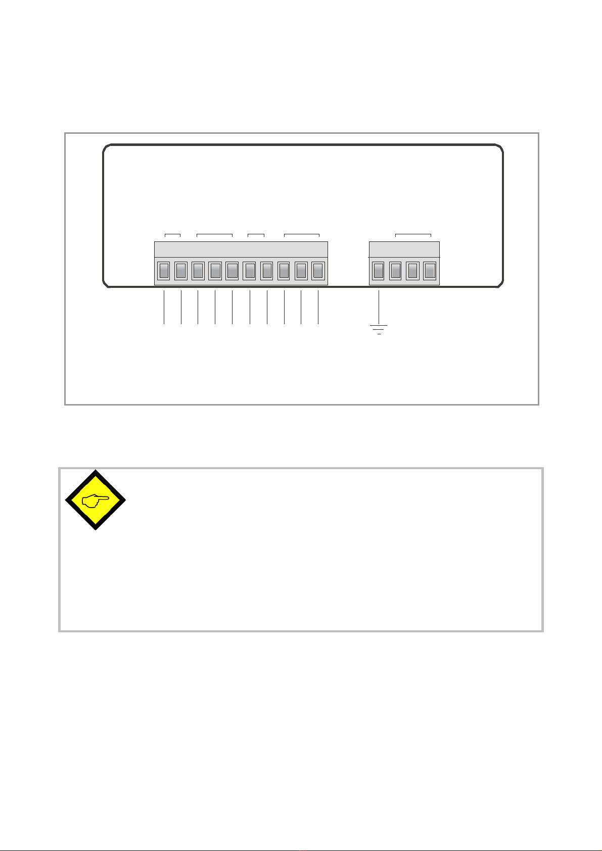
2. Terminal Assignments ...................................................................................5
2.1. Power supply .........................................................................................................6
2.2. Aux. voltage output ...............................................................................................6
2.3. Analogue inputs ....................................................................................................6
2.4. Adjustable Analogue Output.................................................................................6
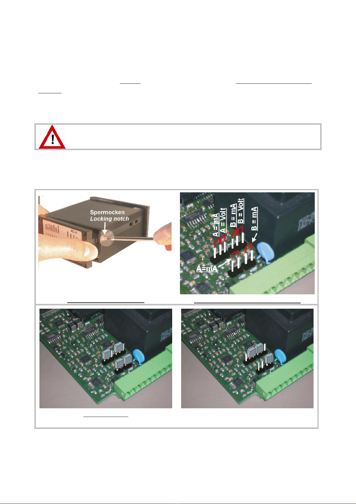
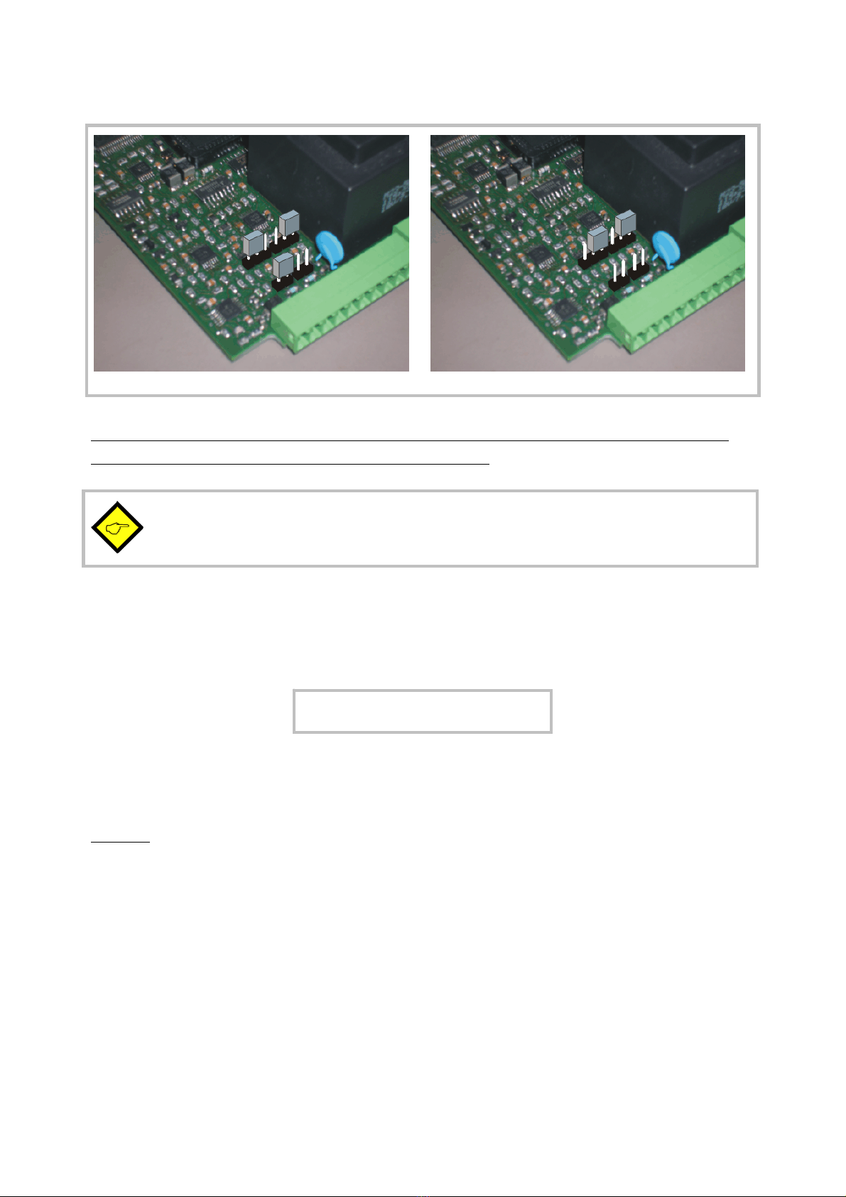
3. Jumper Settings.............................................................................................7
4. How to Operate the Keys...............................................................................9
4.1. Normal display state .............................................................................................9
4.2. Parameter settings ..............................................................................................10
4.2.1. How to select a parameter ...........................................................................................10
4.2.2. How to change parameter settings..............................................................................10
4.2.3. How to store settings ...................................................................................................10
4.2.4. Time-out function..........................................................................................................10
4.3. Teach operation...................................................................................................11
4.4. Set all parameters to “Default“ ..........................................................................11
5. The Parameter Menu ...................................................................................12
6. Setup Procedure...........................................................................................13
6.1. Basic Parameters.................................................................................................13
6.2. Operational parameters ......................................................................................15
6.3. Keypad locking ....................................................................................................15
6.4. Modes of operation.............................................................................................16
6.4.1. Single mode (input A only)............................................................................................16
6.4.2. Dual Mode (Inputs A and B separately) .......................................................................17
6.4.3. Combined Modes (A+B, A-B, A:B, A•B) .......................................................................18
6.4.4. Parameters for scaling of the analogue output............................................................19
7. Commissioning............................................................................................. 20
8. Special Functions.........................................................................................21
8.1. Tare / Offset function..........................................................................................21
8.2. Linearization ........................................................................................................21
8.3. Manual input or „Teaching“ of the interpolation points.....................................23
8.4. Update time of the display and the analogue output .........................................24
9. Technical Specifications ..............................................................................25
9.1. Dimensions..........................................................................................................25
9.2. Technical data .....................................................................................................26
9.3. Commissioning Form ...........................................................................................27

Ax34607b_e.doc / Mrz-08 Page 4 / 27
1. Introduction
Some of the general demands to an up-to-date process controller for automation industry are
always high flexibility, combined with easy and simple operability.
Many applications require two separate analogue inputs for use with single or combined
operation.
Also it may be important to display and evaluate both, linear and non-linear analogue inputs at
an acceptable accuracy, which requires programmable linearization functions.
Process controllers of series AX345 to AX347 have been designed for this kind of requirements.
Model AX 345 provides display function only.
Model AX 346 provides additional analogue outputs instead of the Preselections
Model AX347 provides two additional programmable Preselections with Optocoupler outputs
All other functions within this controller family are fully similar.
The present operating instructions are valid for model AX 346 only.
Separate operating instructions are available for models AX 345 and AX 347

Ax34607b_e.doc / Mrz-08 Page 5 / 27
2. Terminal Assignments
*) The connection of PE is optional and not necessary for safety or for EMC.
However, with some applications, it can be useful to ground the common potential of all
signal lines
•When using this earthing option, please be aware that all terminals marked
GND or AGND will be earthed.
•Multiple earthing on different positions of an installation may cause
problems, especially with poor overall performance of the whole earthing
and screening system!
•The minus potential of analogue inputs is internally connected to the
minus of the DC supply. When you like to use current loops through
several units, it is therefore necessary to supply the units from either AC
power or from several, potential-separated DC sources.
1
GN D ( 0V )
2
+17...30VCD
34567 8910
GND
230 VAC
115 VAC
0 V AC
I nput A
Input B
GND analogue
+24V D C
optional,
see *)
GN D ( 0V )
GND analogue
+/- 10 V
0 / 4 - 20 mA
DC power supply
Inputs
+/- 10 V or
0 / 4 - 20 mA
Aux. output
Analogue out
AC power supply

Ax34607b_e.doc / Mrz-08 Page 6 / 27
2.1. Power supply
The unit accepts DC supply from 17V to 30V when using terminals 1 and 2, and the
consumption depends on the level of the supply voltage (typical 80 mA at 30V or 130mA at 17V,
plus current taken from the aux. output).
For AC supply, terminals 0 VAC and 115 VAC or 230 VAC can be used. The total AC power is
approximately 7.5 VA.
2.2. Aux. voltage output
Terminal 7 provides an auxiliary output of 24 VDC / 150 mA max. for supply of sensors and
encoders. This is valid for AC supply and DC supply of the unit as well.
2.3. Analogue inputs
There are two analogue inputs with common minus potential available (Input A and Input B).
Both refer to the AGND potential of terminal 5 which is internally connected to terminals 1, 6
and GND.
The analogue inputs can be configured for voltage input (+/- 10 V) or current input
(0/4 – 20 mA), by means of internal jumpers (see 2.)
Ex factory, both inputs are always configured for current input.
(see section 3 for jumper settings)
2.4. Adjustable Analogue Output
The outputs provides a voltage output (0 … +10V or -10 … +10V) and a current output 0/4 – 20
mA proportional to the display value. Both analogue outputs refer to GND potential. The
polarity of the output signal depends on the sign shown in the display.
The output resolution is 14 bits and the response time about 58 msec. (see 8.4)
The voltage output accepts output currents of 2 mA, and the current output accepts load
resistors from 0 to 270 ohms.

Ax34607b_e.doc / Mrz-08 Page 7 / 27
3. Jumper Settings
When your input signal is a current of 0-20 mA or 4-20 mA, there is no need to change jumper
settings and you can skip this section.
Where, however, you intend to use one or both inputs for voltage signals, you must change the
internal jumper settings correspondingly.
Wrong jumper settings may cause serious damage to the unit!
To access the jumpers, you have to disconnect the rear screw terminal strips, remove the back
plane from the unit and pull the PCB out of the housing
Removal of the back plane
Location and function of the jumpers
Factory setting:
Input A = current, input B = current
Input A = voltage, input B = current

Ax34607b_e.doc / Mrz-08 Page 8 / 27
Input A = current, input B = voltage
Input A = voltage, input B = voltage
After setting the jumpers, please shift the print carefully back to the housing, in order not to
damage the front pins for connection to the keypad plate.
Current inputs are automatically scaled to an input range of 0/4 – 20 mA.
Voltage inputs use the standard range of +/- 10V.
You are free to measure voltages up to 120 volts DC by use of a remote resistance in series to
the input line (please observe applicable safety standards!). You can calculate the value from
the formula
R = resistance value
V = input voltage
Example: Desired input = 100 volts:
R = 300 – 30 (kΩ) = 270 kΩ
With regard to the scaling procedure described later, the new maximum input with resistance
will work like a 10 volts signal with no resistance
R [ kΩ] = 3 x Vx [ volts ] - 30

Ax34607b_e.doc / Mrz-08 Page 9 / 27
4. How to Operate the Keys
The unit uses 3 front keys for all setup operations. Subsequently, the key functions will be
named as shown in the table below.
ENTER
SET
Cmd
(Command)
The functions of the keys are depending on the actual operating state of the unit.
The following three operating states apply:
•Normal display state
•Setup state
a.) Basic setup
b.) Operational parameter setup
•Teach operation
4.1. Normal display state
You can only change over to the other states while the unit is in the normal
display state.
Change over to Key operation
Basic setup Keep ENTER and SET down simultaneously for 3 seconds
Operational
parameter setup
Keep ENTER down for 3 seconds.
Teach operation Keep SET down for 3 seconds
The Cmd key is only used with the Tare and Reset function, and for the Teach procedure with
linearization (see section 8).
«
)

Ax34607b_e.doc / Mrz-08 Page 10 / 27
4.2. Parameter settings
4.2.1. How to select a parameter
The ENTER key will scroll through the menu. The SET key allows to select the corresponding
item and to change the setting or the numeric value. After this, the selection can be stored by
ENTER again, which automatically changes over to the next menu item.
4.2.2. How to change parameter settings
With numerical entries, at first the lowest digit will blink. When keeping the SET key down, the
highlighted digit will scroll in a continuous loop from 0 … 9 … 0 … 9. When you release the
SET key, the actual digit will remain and the next digit will be highlighted (blink).
This procedure allows setting all digits to the desired values. After the most significant digit
has been set, the low order digit will blink again and you can do corrections if necessary.
With signed parameters, the high order digit will only scroll between the values “0” (positive)
and “-“ (negative)
4.2.3. How to store settings
To store the actual setting, press the ENTER key, which will also automatically scroll forward
the menu.
The unit changes from programming mode to normal operation when you keep down the ENTER
key again for at least 3 seconds.
4.2.4. Time-out function
The “time-out” function will automatically conclude every menu level, when for a break period
of 10 seconds no key has been touched. In this case, any entry which has not been confirmed
by ENTER yet would remain unconsidered.

Ax34607b_e.doc / Mrz-08 Page 11 / 27
4.3. Teach operation
The Time-out function will be switched off during all Teach operations
Key Function
«
ENTER will conclude or abort any Teach operation in progress
SET function is fully similar to normal set-up operation
Cmd will store the display value to the register and will change over to the
next interpolation point.
For details of the Teach procedure see section 8.3.
4.4. Set all parameters to “Default“
At any time you can return all settings to the factory default values.
The factory default settings are shown in the parameter listings in section 6.
When you decide to set all parameters to „default“, please be aware that all
previous settings will be lost and you will need to do the whole set-up
procedure once more
To execute the „Default“ setting function:
•Power the unit down.
•Press the ENTER key.
•Power the unit up again while the ENTER key is kept down

Ax34607b_e.doc / Mrz-08 Page 12 / 27
5. The Parameter Menu
The menu provides one section with “basic parameters” and another section with “operational
parameters”. On the display you will only find those parameters which have been enabled by
the basic settings. E.g. when the Linearization Functions have been disabled in the basic set-up,
the associated linearization parameters will also not appear in the parameter menu.
All parameters, as good as possible, are designated by text fragments. Even though the
possibilities of forming texts are very limited with a 7-segment display, this method has proved
to be most suitable for simplification of the programming procedure.
The subsequent table is to show the general structure of the whole menu only.
Detailed descriptions of all parameters will follow in section 6.
Menu overview:
Basic Parameters Operational Parameters
Single Mode Dual Mode Verknüpfte Modes
"modE " „inPutA" „inPutA" „inPutA"
"briGht" „StArtA" „StArtA" „StArtA"
"UPdAt” „End A" „End A" „End A"
"CodE " „dPoi A" „dPoi A" „dPoi A"
"LinEAr" „FiLt A" „FiLt A" „FiLt A"
"A-CHAr" "OFFS A" *) "OFFS A" *)
"GAin " „inPutb" „inPutb"
"OFFSEt" „StArtb" „StArtb"
“Crnd” „End b" „End b"
„dPoi b" „dPoi b"
„FiLt b" „FiLt b"
"OFFS b" *)
*) appears only „n) FAc"
when Tare function is „d FAc"
enabled „P FAc"
„dPoint"
"An-bEG"
"An-End"
**) appears only "P01_H " **)
when linearization is "P01_Y " **)
enabled ---->
"P16_H " **)
"P16_Y " **)

Ax34607b_e.doc / Mrz-08 Page 13 / 27
6. Setup Procedure
6.1. Basic Parameters
In general, the parameters described subsequently must be set with the very first
commissioning of the unit only.
Menu Text Default
Mode of operation
Single input operation (input A only)
Dual input operation (input A and input B separately)
Sum operation (input A + input B)
Differential operation (input A – input B)
Dividing operation (ratio A : B)
Multiplying operation (product A x B)
Brightness of the display „100“
„ 100“ 100% of maximum brightness
„ 80“ 80% of maximum brightness
„ 60“ 60% of maximum brightness
„ 40“ 60% of maximum brightness
„ 20“ 20% of maximum brightness
Update time of the display „0.300“
Updates the display every x.xxx seconds. Setting range from
0.050 to 9.999 seconds.
Keypad interlock code
Keypad enabled continuously
Keypad locked for any access, see 6.3
Mode of linearization
No linearization. The corresponding parameters will
not appear in the menu.
Linearization for the numeric range 0 – 99999.
Interpolation points to be set in the positive range
only (negative values will appear as a mirror).
Linearization over the full range
–99999 to +99999

Ax34607b_e.doc / Mrz-08 Page 14 / 27
Menu Text Default
Analogue output characteristics
Full range from -10V to +10V
Positive range only 0 – 10V
Current range 0 – 20 mA
Current range 4 – 20 mA
Analogue output swing 0 … 1000 1000
Setting 1000: results in a full-scale output of
10 V respectively 20 mA
Setting 200: reduces the full scale output to
2 V respectively 4mA
Analogue zero definition -9999 … 9999
0
Setting 0: Output generates 0 V respectively
0 mA with zero in display.
Setting 5.000: Output generates already 5 V
respectively 10 mA with zero in display.
Command key enable
The Command key is switched off and no Offset values
will appear in the menu
The Cmd key will execute the Tare/Offset function
The Cmd key will execute the Teach function
The Cmd key will execute both, the Tare and the Teach
function

Ax34607b_e.doc / Mrz-08 Page 15 / 27
6.2. Operational parameters
After the basic setup, you can access the operational parameters by pressing ENTER for at
least 3 seconds. You will only find those parameter texts that are relevant for your mode of
operation.
The parameters for scaling of the analogue output will appear at the end of each menu. Since
they are absolutely the same with all operating modes, these parameters will be described
separately in section 6.4.4.
To exit the menu, keep again ENTER down for at least 3 seconds, or just wait for the automatic
Time-Out function.
6.3. Keypad locking
When the code locking of the keypad has been switched on, any key access first results in
display of
To access the settings, within the next 10 seconds you have to press the key sequence
«
«
«
or the unit will automatically return to the normal display mode

Ax34607b_e.doc / Mrz-08 Page 16 / 27
6.4. Modes of operation
6.4.1. Single mode (input A only)
Menu Text Setting Range Default
Input A range
Set the desired range for input A
Voltage +/-10V
Current 0-20 mA
Current 4-20 mA
Start value
Value which the unit will display with a
zero input signal of 0 volts or 0/4 mA
-99999 … 99999 0
End value
Value which the unit will display with a
full scale input of 10 volts or 20 mA
-99999 … 99999 1000
Decimal point for signal A
Select the desired position of the decimal point
00000.0
000000 No decimal point
00000.0 one decimal position
---->
0.00000 five decimal positions
Average filter input A
Adjustable floating average filter for smoothing
the display with unsteady input signals
2
No filtering
2,4,8,16 Number of floating averaging
cycles
Offset value for input A *)
Offset value for the zero displacement of input
A signals
-99999 … 99999 0
*) When Tare function is switched on only

Ax34607b_e.doc / Mrz-08 Page 17 / 27
6.4.2. Dual Mode (Inputs A and B separately)
A
B
With this mode, the SET key selects between display of channel A and
display of channel B, and the bar of the high order LED indicates which
of the two channels is actually in display.
Menu Text Input Range Default
Input B range
Set the desired range for input B
Voltage +/-10V
Current 0-20 mA
Current 4-20 mA
Start value B
Value which the unit will display with a
zero input signal of 0 volts or 0/4 mA
-99999 … 99999 0
End value B
Value which the unit will display with a
full scale input of 10 volts or 20 mA
-99999 … 99999 1000
Decimal point for signal B
Select the desired position of the decimal
point
000000
000000 No decimal point
00000.0 one decimal position
---->
0.00000 five decimal positions
Average filter input B
Adjustable floating average filter for
smoothing the display with unsteady input
signals
No filtering
2,4,8,16 Number of floating averaging
cycles
Offset value for input B *)
Offset value for the zero displacement of
input A signals
-99999 … 99999 0
*) When Tare function is switched on only

Ax34607b_e.doc / Mrz-08 Page 18 / 27
6.4.3. Combined Modes (A+B, A-B, A:B, A•B)
These modes allow displaying either the single channels A and B or the calculated result
according to the selected combination. The SET key allows scrolling between the three
displays.
A
B
<AB>
The upper bar of the high order digit indicates that you display
channel A.
The lower bar of the high order digit indicates channel B.
When no bar is lit, the display shows the result of the calculation,
according to the combination set.
When you use one of the combined modes, you will first have to do the same settings as with
the “Dual” mode for individual display of inputs A and B.
The combined display will then be the result calculated from both single values.
The following additional parameters provide a final scaling facility, so you can read out the
result of your combination in proper engineering units:
Menu Text Setting Range Default
Proportional Scaling Factor
Multiplies the result by this setting
-10000 … 10000 1000
Reciprocal Factor
Divides the result by this setting
1 … 99999 1000
Additive Constant
Adds or subtracts this setting
-99999 … 99999 0
Decimal Point
Sets the decimal point for the combined
display value
000000
000000 No decimal point
00000.0 one decimal position
---->
0.00000 five decimal positions
Calculation Formula:
Final display value
=
value calculated from <AB>
x
m_Fac
d_Fac
+/-
P_Fac

Ax34607b_e.doc / Mrz-08 Page 19 / 27
6.4.4. Parameters for scaling of the analogue output
The analogue output operates at any time under control of the display value and the scaling
parameters explained below. This means that the analogue signal also will contain the same
calculations, combinations and linearization as shown in display.
Output swing and zero definition have already been set with the basic parameters under 6.1.
The operating range of the output can be set by means of the following parameters:
Menu Text Setting Range Default
Analogue Begin:
Start value of the operating range
-99999 … 99999 0
Analogue End:
End value of the operating range
-99999 … 99999 1000
It is easy to understand that these settings allow to either converting the full range or only a
selected window of the full range to analogue.
Example: Anabeg = “-1500” and Anaend = “2100”
will generate the initial value as defined under “Offset” with a display of
“-1500”, and the final value as defined by “Gain” with a display of “2100”
(see 6.1 Basic settings)

Ax34607b_e.doc / Mrz-08 Page 20 / 27
7. Commissioning
Commissioning of this unit is easy and uncomplicated when following the subsequent steps:
Step Action See section
1 Analogue inputs •Set jumpers 3
2 Basic settings •Select Operation mode 6.1
•Keep linearization and Tare function off firstly 6.1
3 Parameter settings •Configuration of the analogue inputs, scaling
of the display
•If applicable, select combination and final
scaling
6.4
6.4.3
•Configuration of switching outputs
6.4.4
4 Supplementary
functions
•Set Tare function and Linearization, if
applicable
8
5 Analogue Output •Scaling of the analogue output signal 6.1 and 6.4.4
A Set-Up Form is available in the appendix of this manual, which may be used for a most
convenient and clearly arranged setup procedure.
It is advisable to do settings for Tare and linearization functions quite at the end, after all other
functions have already proved to work fine.
This manual suits for next models
2
Table of contents
Other Motrona Measuring Instrument manuals

Motrona
Motrona AX320 User manual

Motrona
Motrona MS 640 User manual

Motrona
Motrona touchMATRIX DP350 User manual

Motrona
Motrona IX 345 User manual

Motrona
Motrona SD Series User manual

Motrona
Motrona TouchMATRIX DM350 User manual

Motrona
Motrona DS230 Series User guide

Motrona
Motrona IX348 User manual

Motrona
Motrona DX350 User manual

Motrona
Motrona AX 345 User manual