Electrical Requirements
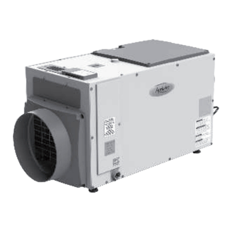
The ATTIC DH200 can be connected to a typical 115 VAC socket. This appliance uses 4.9
Amps and 80°F and 60% RH. Find the dehumidifier in a territory where the wire's length (9')
effectively arrives at a 115 VAC electrical outlet with at least 15 Amp circuit limit. Whenever
utilized in a region that may get wet, a GFCI ensured circuit is suggested. For further
information consult local electrical codes. Abestorm offers an assortment of control gadgets for
use with the ATTIC DH200. The control is to be found remotely from the dehumidifier and set
in the space to be molded. A low voltage (24 Volt) control MUST be utilized with the
ATTIC DH200 and MUST be associated with low voltage (18-22 measure) indoor regulator wire.
DRAIN INSTALLATION
You can condensate the drains easily by gravity through the drain port. Use 0.75” male PVC NPT
pipe. Also, route every single drain to drain. If possible install a trap. All in all, be careful when
installing the drain pipe to the drain port. You can make use of an adjustable wrench to protect
the drain port from damage. An optional water removal pump kit may be fixed if a lift is needed
to dispose of the water. You can contact the company if you would like to order a pump kit.
Duct Supply and Return
In order to promote the rate at which dehumidification occurs, you can add the supply and/or
return duct to help circulate air. You can make use of the return duct to draw moist and warm air
from the near ceiling in order to obtain optimal drying. In a simpler remote installation procedure,
you can make use of the humid room and the Abestorm discharge room. The Uni-P dehumidifier inlet
usually draws air from the room where it is installed. For that reason, this installation procedure
works well if the unit is installed in a room that has got adequate air flow. Such rooms may
include rooms with the wall grill, louvered doors, and/or high door undercut. Such conditions
promote airflow and hence, eliminates the requirement to remote mount the humidity controller.
Warning: it is important that you first seek guidance from a qualified device operator before you
opt to use the device as described above. The experts will provide you with instructions on how
to complete the procedure. If backdraft devices are such as the hot water heater are present in
the place that needs to be dehumidified, it is important that the manufacturer or certified service
provider completes the installation.
It may be necessary to slightly pressurize and/or dehumidify the room if the dehumidifier is to be
located in a smaller room that is separate from the main area that requires dehumidification. The
purpose of pressurization is to make sure that any open combustion devices present in the room
do not backdraft. Backdraft can be prevented by simply allowing the abestorm dehumidifier to
release dehumidified air into the room where it is located. It can also be prevented by installing a
circulation pipe from the humid room into the dehumidifier inlet. All in all, there should be
adequate air circulation between the two rooms for this procedure to work well.
WARNING!
Attic DH200 remote control is operated by a low-voltage alternating current (24 VAC). High
voltage circuits must be ignored to avoid any inconvenience.
CAUTION!
Try not to permit the wires of the 24V terminal to interact with the wires from the COM terminal or
DMPR terminal, in any case the transformer will be harmed.
CAUTION!
Attic DH200 contains some terminals which accommodate some specific controls.
Electrical Precautions
The Controlles can not be installed where it may not precisely sense the relative dampness for
example, located close to HVAC supply registers, close to outside entryways, on an outside wall,
close to a window, or near a water source.
ATTIC DH200 contains screw terminals which are marked with labels to avoid confusion.
Before making control, connections make sure to consult the electrical schematic where the control
section is present of the manual or use access panel of the ATTIC DH200.
TRANSFO
RMER
PCB
FUSE
NO COM
IN-FAN
N
RT
TEMP.SE
NSOR
GRN
RUN
CAP.
C
S
R
COMPRESSOR
GRN
BLACK
RED
WHITE
A1~A9
EX-FAN
MOTOR
N
N
LN
BROWN
RUN
CAP.
BLACK
BROWN
BLUE
FAN
GRN
TRANSF
ORMER
To ensure that the unit drains well, follow these steps:
While cleaning the drain, feet should be extended in such a way that the machine is raised two and a
half feet from the ground.
After the hose gets in contact with the ground, guarantee that you coil the channel hoseunderneath
itself or attempt to situate a spacer to help lift the hose at any rate one feet starting from the ground.
Along these lines the procedure assists with guaranteeing that the unit depletes well.
5 6
