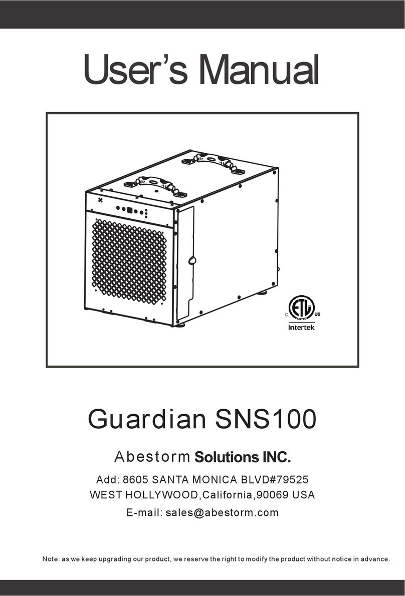
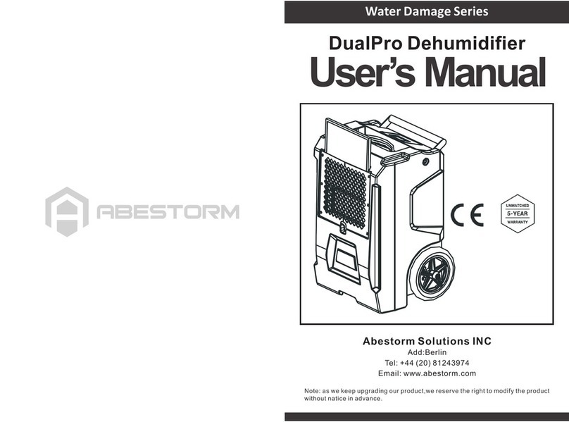
Abestorm Water Damage Series User manual

User’s Manual
Note: as we keep upgrading our product,we reserve the right to modify the product
without natice in advance.
Abestorm Solutions INC
Water Damage Series
Add:Berlin
Tel: +44 (20) 81243974
Email: www.abestorm.com
AbesTec 4000i Dehumidifier

Operation and control instructions
Duct instructions
Transportation and storage
Maintenance
PUMP PURGE BUTTON
SYSTEM MESSAGES
Troubleshooting
Specifications
Important Notes
Warranty Registration
Before first use
Limited Warranty
Warranty Exclusions 18
17
16
14
12
12
10
10
8
4
4
2
3
Important Notes
The unit should not be altered or modified in any way. Only use replacement parts approved
by Abestorm. Modifying or using components that are not approved could cause a hazard,
thus voids the warranty. For assistance, reach any Abestorm dealers near you.
Warning!
CORRECT PLUG REMOVAL
Hold the IEC plug and pull straight.
Damage to the IEC receptacle or dehumidifier due to incorrect removal of the
power cord is not covered by the limited warranty. Besides, the IEC power cord is
bound to experience wear.
Examine the power cord for damage before use. Do not use it if the cord is damaged. To unplug from the
power supply, always grasp the plug and not the cord.
WARNING! Risk of Electric shock, hot surface, rotating fan hazards. Power off the
unit and unplug from supply before opening the front cover for servicing or
cleaning. The unit must be connected to a grounded power supply.
The three-prong plug should only be inserted into a matching outlet that is electrically grounded. The cord
should never be used with an adapter. Do not remove the third prong from the plug. Do not connect with
an extension cord.
The dehumidifier should run on a 115Volts/60Hz circuit connected to a GFCI (Ground Fault Circuit
Interrupter) device.
1 2
The Abestorm® AbesTec 4000i water damage dehumidifier controls humidity in an environment by getting
rid of the water vapor present in the air. The Abestec 4000i is ideal for structural drying, water damage
restoration, construction, and is particularly adapted for eliminating moisture from structural contents
and materials in environments that face between low and medium Relative Humidity, and cold
temperatures where the traditional refrigerant dehumidifier are less efficient.
Spare Parts 15

Do not try to repair the equipment on your own. Contact Abestorm to get
service from Authorized Service Centers.
The motor and wiring should be kept dry at all times.
Warranty Registration
To register your dehumidifier, visit abestorm.com. Registering the unit allows us
to assist you in the operation, maintenance, and servicing of your unit. Also, we will be able to
contact you for any important safety information on your Abestorm dehumidifier. For servicing,
present information on the unit's model, serial number, and proof of purchase, and reach your
local distributor to obtain a return material authorization (RMA).
For additional questions concerning your dehumidifier, contact your local installer or
call Abestorm at 44(20)81243974.
INSTRUCTIONS FOR GROUNDING
WARNING: Incorrect connection of the unit to a grounding conductor may cause an
electric shock. Consult with an approved electrician or service person for clarity on
whether the outlets are grounded properly. If the provided plugs do not fit the
appliance, do not try to modify them. Instead, have a qualified electrician install the
correct outlets.
This equipment should only be used on circuits that have a nominal rating of not
above 120V.
The unit Should Be Handled Carefully.
Position the unit on a surface that is level and stable when running. Do not throw, drop, or
place the unit where it could tumble. Rough handling of the unit could lead to damages
that void the warranty. It could also create a hazardous environment.
The equipment is intended for commercial and household use only.
Before first use
The unit features
2 duct rings with an adaptor kit inside the storage section.
A three-millimeter Allen wrench for installing the component.
Required: Install the Reactivation Air Outlet duct ring. Attach the Reactivation
Duct Ring (Figure B)
Optional: Install Air Inlet duct ring Fix on the inlet with the included
thumbscrews, (Figure B)
Optional: Install Process Air Outlet screws
You may install the Process Air Outlet Adaptor Kit using the included offset
screws, (Figure B).
Operation and control instructions
Place the equipment away from obstructions that may hinder the airflow in and
out of the dehumidifier. Route a reactivation outlet duct outdoors through a dryer
vent or window adapter.
Positioning the Dehumidifier
3 4

49-109J F533 2 Legend Brands, Inc.
are properly grounded. Do not modify the plugs pro-
vided with the appliance – if the plugs do not fit the
outlets, have proper outlets installed by a qualified
electrician.
This equipment is for use on circuits with a nominal rat-
ing of no more than 120V.
Handle the unit carefully
Always operate the unit on a stable, level surface. Do
not drop, throw, or place where it could fall. Rough treat-
ment can damage the unit, and may create a hazardous
condition or void the warranty.
This unit intended for household and commercial use.
BEFORE FIRST USE
The unit is shipped with two duct rings and an adaptor kit
packed inside the storage compartment. A 3 mm Allen
wrench is required for installation of these components.
Required: Install Reactivation Air Outlet duct ring
Install the Reactivation Duct Ring, See Fig. B.
Optional: Install Air Inlet duct ring
Attach to inlet with the thumbscrews provided. See Fig.
B.
Optional: Install Process Air Outlet offset screws
The Process Air Outlet Adaptor Kit may be installed us-
ing the offset screws provided. See Fig. B.
CONTROLS AND OPERATING
INSTRUCTIONS
Positioning the Dehumidifier
For best results, operate your dehumidifier in an en-
closed area. Close all doors and windows that open to
the outside to maximize water removal efficiency. Place
your dehumidifier away from any obstructions that could
block airflow into and out of the unit. Duct reactivation
outlet outdoors through window adapter or dryer vent.
Plug in electrical cords
Always plug the cords firmly into the sockets in the
top compartment first, then into the wall outlets. En-
sure that the cords are routed properly through the
cord cutout notch before closing the storage com-
partment lid.
NOTICE: The power cords of the DriTec must be
plugged into separate GFCI-protected 120V outlets rated
for at least 15A.
CONTROL PANEL
Press the ON/OFF to turn the unit on.
Fig. A: Parts Identification
Air filter
Power sockets inside
compartment. Stor-
age for power cords,
react ducting.
Air inlet
Reactivation
Air Outlet
(installation
of duct re-
quired)
Control panel
Process Air Out-
let (optional duct
attachment kit
provided)
Plug-in Electrical cables
Ensure that the cables are firmly plugged in the top compartment and then to the wall
outlets. Make sure that you route the cables correctly through the cutout notch before
placing the storage compartment lid.
Notice: The DriTec power cords must be connected to a separate 120V outlet with a
Ground Fault Circuit Interrupter, and a minimal rating of 15 Amperage.
ON/OFF
DISPLAY MENU
MENU SELECTION
UP KEY
WATER REMOVAL
When the unit is powered, the screen will display PLEASE
WAIT WARMING UP. Upon completion of the warm-up
procedure it will display UNIT ON XXX
HRS and will cycle between INLET XX% (RH) and INLET
XXX°F.
The Display Menu is used for cycling through the displays
of additional User Settings and dehumidifier conditions.
Press once on the ON/OFF key to go back to the main
menu.
Alter system settings. The MENU SELECTION key works
as the UP key when cycling through the selected
setpoints. Press once and release to display the amount
of water eliminated in pints per day. After five minutes of
operation, the unit displays WATER REMOVAL XXX
PINTS/24HRS. After a few seconds, the display
automatically returns to reading "Unit on.
For the best results, use your dehumidifier in an area
that is enclosed. Close all windows and doors opening to
the outside to increase the water removal efficiency.
Note: Connect the unit only to two different circuits of 15A. A bright green illumination on the face of the screen
shows that the connection is correct. The green light will not illuminate if both the power cords are inserted
into the same circuit or when using a single cord.
For maximum efficiency, use both circuits while ensuring that the green light illuminates.
However, the dehumidifier may run on one power cord if the second circuit is not
available. Plug into Circuit 1. When using a single power cable, the dehumidifier
operates at half the rated performance.
Positioning the Dehumidifier
When connecting the dehumidifier to power for the first time, the control panel briefly cycles
through various readouts. This is a regular self-diagnosis procedure for the unit; thus,
no intervention by the user is required.
Ducting Setup
Note, the unit is designed for indoor use only. The equipment should not be exposed to snow or rain.
If any electrical component becomes wet, allow for thorough drying before operating the unit.
Reactivation Outlet Ducting
To attach the ducting on the duct ring, use the provided duct clamp. Ensure that the reactivation air is ducted
to the outside.
NOTICE
During operation, condensate may collect inside the reactivation duct. Water should not run back into the unit;
this could damage the unit. Or lead to a shock hazard.
Note: The temperatures in the React Out ducting may reach 66°C (150°F).
Only use the heat-rated ducting provided.
Process Outlet Ducting
The out air should be ducted, where more drying is required. It should only be used with a lay-flat ducting.
Maximum Ducting length
For maximum performance, ducting should not exceed these lengths:
Reactivation air: 20 feet |. 6m
Inlet air: 30 feet |. 9.1m
Process air: 10feet | 3 m
For additional ducting options, see figure C
5 6
USER SETTINGS
Menu items that are followed by the greater-than (>) symbol can be adjusted. For menu
items with read-on data (CURRENT, REACT & HEATER 1, INLET, OUTLET), the display
returns to normal mode if no key is selected within five minutes. In other menu selections,
the display returns to normal mode after about twenty seconds. Items lacking the (>)
symbol are only for information and cannot be reset or adjusted.
MAIN MENU
Display Menu
Press
SUBMENUS: Press MENU SELECTION to change the setting
Ducting Options
A.Basic Setup
It is recommended to duct the Reactivation Outlet to an outside location.
The Reactivation ducting MUST be connected to a reactivation outlet.
Ducting should not be longer than six meters (20 feet). Set the ducting with the
least number of bends that can be attained.
Tips
The ducting should slope downwards away from the equipment.
Always duct the Reactivation Outlet, preferably to an outdoor location.
Notice: Sometimes, water may collect inside the Reactivation ducting. Thus, whenever
the ducting is moved, take care not to spill water in the machine or on the floor.
It is recommended to duct the Reactivation Outlet to an outside location.
B.Advanced Options
Duct inlet (2) to maximize performance
Allowing drier and colder air into the inlet increases the performance of the desiccant.
7 8

Tips
Avoid ducting the process air from a refrigerant dehumidifier, since
it could impair the performance of the desiccant.
Duct process outlet (3) for even drying
Keep the dehumidifier near a suitable area for air reactivation and duct the
process air outlet in areas that are hard-to-reach.
Tips
For directing the process air to areas that are affected, use a lay-flat ducting.
For a wider supply of process air, make cuts of between fourto six inches along the
lay-flat at intervals. Tie off the end to increase efficiency.
Use in low clearance areas/ crawlspaces. When controlling clearance/ low ceiling
areas, operate the unit laid on its back. Reactivation outlet 1 should be ducted
outdoors. If preferred, the process air outlet 3 and air inlet 2 may be ducted as
explained in setups B1 and B2 above.
Tips
For even air distribution, the process air can be ducted between floor joists. For wider
distribution, make slits of six inches along the lay-flat ducting at intervals, and seal off
at the end to release dry, warm air in the areas required.
Use in crawlspace/low clearance areas. Operate the unit on its back in low
ceiling/clearance areas. Duct the reactivation outlet (1) outdoors. If desired, the air
inlet (2) and process air outlet (3) may be ducted as described in B1 and B2 above.
Tips:
Transportation and storage
Note: Handle the equipment with caution. Subjecting it to rough handling may cause
damage and create a perilous condition or render the warranty void.
The control panel should NOT be exposed to rain, moisture, or snow.
Ensure that the unit is secured before storage and transporting to avoid damaging
impact on the internal components.
During transportation, ensure that the unit is secured to prevent possible sliding and
cause injury to the occupants in the vehicle.
Maintenance
**For more detailed instructions, visit www.unipdry.com**
WARNING! RISK OF ELECTRIC SHOCK. Disconnect the unit from the power
supply before servicing or cleaning.
9 10
WARNING! Dust and contaminants exposes you to hazards. The use of hand
gloves and respirator mask is highly recommended. If you realize that the
product has been exposed to a possibly harmful contaminant, clean thoroughly
by disinfecting before operating.
As Needed (Exterior components)
Inspect the filter. Replace if the accumulation of debris and dust is visible.
Note: Used filters should only be replaced with new Abestorm filter part #
F590 (24pack). Other types of filters do not offer adequate airflow or filtration.
The filters are individually wrapped to preserve effectiveness infiltration. Take
the filter out of the wrapper before installing it into the unit.
To retain appearance, wipe the exterior and interior surfaces using a damp cloth.
Inspecting the reactivating air outlet ducting for splits, cracks, or breaks is recommended.
Replace as necessary using appropriate heat-proof ducting.
NOTE: Risk of electric shock. Unplug the unit from the power supply before removing
the side panels.
As Needed (Interior parts), see figure D.
NOTE: The equipment features sensitive electronic sensors. To protect the sensors and
lead wires from possible damage, avoid exposing them to cleaning solution or water.
The following supplies and tools are necessary for the completion of the maintenance
procedures outlined in this manual.
Three- millimeter Allen wrench, or cordless drill and bit
Clean pieces of cloths
A vacuum cleaner with a high-pressure nozzle or soft brush tool
Remove the side panels. Unscrew the screws from the air inlet/ react panel.
NOTICE: The inlet RH/ Temp sensor cable is attached to the inside of the panel and should be attached
before placing the panel aside. Unclip the plug and slide the cable downwards from the cable tie to
remove the cable. Once it gets released, set aside the panel.

Fig. D: Interior views
Notice! RH/Temperature
The sensor cable is attached onto the interior of panel. Before
Setting aside the panel, unclip and slide it out from the cable tie
Advanced Pump Cleaning
Complete as needed
1. Press the drain button to drain the water from the reservoir (a wet-dry
vacuum or towels can be used to remove any remaining water).
2. Unplug the dehumidifier and remove the cover so you have access
to the pump.
3. Remove the pump head from the reservoir by unscrewing the screw.
Wipe reservoir clean with a paper towel.
4. Reassemble pump.
5. Mix a 16 ounce solution of bleach (1 oz bleach + 15 oz water) OR
vinegar (4 oz white vinegar + 12 oz water).
6. Pour the cleaning solution into the drain tray at the base of the coils.
If any cleaning solution gets on the coils, flush with water.
7. Allow solution to soak for 15 minutes.
8. Reconnect the dehumidifier to power.
9. Fill the reservoir with water (16-32 ounces) and flush/cycle the pump
at least 2x.
Unit Diagram
Handle
Side Panel
Filter Cover
Control Panel
Pre-Filter
Discharge Grille
Power Cord
Auxiliary Terminals
Drain Hose
Connection
11 12
Before setting aside the panel, detach the sensor cable. When
Replacing the panel, remember to reinstall the cable.
Air in/ react out panel. Only remove this panel
for routine cleaning and inspection
Storage compart-ment.
Blower
Bel t ten sio ner
(seedetailbe-
low)
Desiccant
rotor
Reactair
outlet
Belt tensioner.Lift arm upward
to release belt.
Inspect the blower and clean as necessary
Ensure that the impeller rotates without restrictions. Wipe clean or vacuum all surfaces.
Inspect the desiccant rotor and clean as necessary
Use pressurized air or dry-vacuum to get rid of dust collected on the rotor.
Inspect the rotor belt. Check for cracks and excessive wear. For replacement
options, contact your local distributor or retailer.
Vacuum the interior to get rid of debris and dust. Wipe the interior surface using a
clean and dry cloth. Do not attempt to use water or any kind of cleaning solution.
Take caution not to damage the electronic sensors and lead wires.
Reattach the side panel: Reattach the sensor cable inside the panel. Thread the cable
upwards over the zip tie and plug it in. Install the screws and fasten sing fingers only,
starting from the top working downwards. Once the screws are correctly started, use a
hand screw to tighten them lightly, do not overtighten the screws. Also, do not tighten the
screws using a power screw since they tend to impact more pressure.
PUMP PURGE BUTTON
When the Pump Purge Button is used, the control panel displays
the following messages.
C O N T R O L P A N E L
M E S S A G E E X P L A N A T I O N
PLEASE WAIT
CALCULATING
PERFORMANCE
XXX PINTS/24H
The dehumidifier is calculating water removal..
The unit displays the calculated water removal
in Pints per day.
SYSTEM MESSAGES
The Control Panel will display the following messages based on system performance
and environmental conditions. User action, if any is required, is indicated in
the third column.
C O N T R O L P A N E L
M E S S A G E E X P L A N A T I O N U S E R A C T I O N
INITIALIZING Unit is powering up.
FIRMWARE
VERSION XXX
Indicates the control board
firmware version number
None
None

13 14
Fan will not operate until unit reaches
proper operating temperature,
approximately 10 seconds
Model number
F533XX
OFF/ON
PLEASE WAIT
WARMING UP
UNIT ON XXXX HRS
INLET XXX°F / XX%
PLEASE WAIT
COOLING
XXXXX POWER
FAILURE>
CLEAN FILTER
> XXXXX
CLEAN ROTOR
> XXXXX
None
None
None
None
None
None
Press the > key to reset
Change or clean filter.
Press the > key to reset
Clean rotor. Press
the > key to reset
Unit has finished powering
up and is operating
First line: specifies total operating
hours.Second line: Toggles between
displaying inlet temperature and inlet
RH every two seconds.
HUMIDISTAT INLET
XXX°F / XX%
First line: indicates that dehumidifier
is in humidistat mode Second line:
Toggles between inlet temperature
and inlet RH every 2 seconds.
Fan will operate until unit cools down.
Approx 30 sec-onds.
Indicates power has been interrupted
during operation.
Prompt to change or clean the filter.
Prompt to clean the rotor.
ERROR MESSAGES
The control board displays an error message ("ER") when an error is detected. When this
occurs, unplug the unit from the power supply and again plug it back. Usually, this resets the
electronics, and the equipment will function normally. If the error message shows again, refer
to the explanation and options below. If the following solutions do not solve the problem, reach
an authorized service center near you.
IMPORTANT! The message "POWER FAILURE" is not an error message. When this
message is displayed, it indicates that the power supply was interrupted and then
reestablished. Use the MENU SELECTION key to clear the message.
Pump Alarm- E4 Error Code
**UNIT WILL NOT FUNCTION UNTIL ERROR CODE IS CLEARED.
If E4 (pump alarm) is shown on the display, complete the following steps:
1. Reset the unit by unplugging the power cord and then reconnecting it.
2. Manually check to see if the pump is operational by pressing the drain button. Check
if the pump energizes and de-energizes properly. Additionally, check to see if any water
purged from the system.
3. If you haven’t cleaned the system recently, check the discharge line for an obstruction,
then clean as described in the Maintenance section.
4. Replace the hose and/or pump, if maintenance alone isn’t sufficient.
Spare Parts
Fan Components
Filter + External Components
Cables
Duct + Ventilation Accessories
N-100
N-101
N-102
N-1209
N-1206
N-1208
N-1207
Main Control Board
Display Board
RH/Temp. Sensor
Fan Motor
Complete Fan Assembly
Fan Capacitor
N-1210
N-1211
N-1205
N-1200
N-1201
N-1202
N-1203
N-125
Prefilter
MERV 8
HEPA
Carbon Filter
Foot adjustable
Display/Control
Inernal Components
N-120
N-121
N-122
Temp/RH Sensor Cable
Display Ribbon Cable
CaТ: 5 Port Internal Cable
N-1204 Supply Duict Collar
Assembly
Compressor
Compressor Capacitor
Coil Assembly
Condensate Pump
Assembly
W-100
W-101
W-102
Remote Control Assembly
(includes W-101 and W-102)
Remote Control
Remote Control Cable
Remote Control
Troubleshooting
Display is Blank
No Airflow
Error Code:E1
Error Code:E4
Error Code:LO
Error Code:HI
Tripped GFCI
Outlet or Breaker
Cause Solution
Poor Connection
Power Outage
Filter is dirty
Air Inlet or Outlet
is Blocked
Humidity Sensor or
Communication Error
Problem with Pump
Room Temperature
is below 33℉
Room Temperature
is above 105℉
Not a Dedicated Circuit
Defective GFCI Outlet
Dirt, Dust, or
Moisture on Outlet
Lightning or Externa
Electrical Surge
Possible Dehumidifier
Issue
Verify that both ends of the
cord are plugged in
Reset power
Clean the Filter
Clean the blockage
Check to ensure that the sensor wire
is connected at both ends. if no issues
are visible, the sensor may be faulty.
Verify that the pump is properly
installed and functioning. If so, unplug
the unit for two minutes,then restart.
Increase the room temperature so it is
within operating range (above 33℉). If
error still displays, check sensor.
Decrease the room temperature so it is
within operating range (below 105℉).
If error stille displays, check the
sensor
Identify all sources connected to outlet
and confirm source of trip.If it is
dehumidifier, contact technical
support. If not, move dehumidifier to
dedicated circuit for future use.
Replace Outlet
Clean or Replace Outlet as necessary
Reset or Replace Breaker/GFCI, as
necessary
If none of above options work, contact
technical support
Symptom
12 13

15 16
Spare Parts
Fan Components
Filter + External Components
Cables
Duct + Ventilation Accessories
N-100
N-101
N-102
N-1209
N-1206
N-1208
N-1207
Main Control Board
Display Board
RH/Temp. Sensor
Fan Motor
Complete Fan Assembly
Fan Capacitor
N-1210
N-1211
N-1205
N-1200
N-1201
N-1202
N-1203
N-125
Prefilter
MERV 8
HEPA
Carbon Filter
Foot adjustable
Display/Control
Inernal Components
N-120
N-121
N-122
Temp/RH Sensor Cable
Display Ribbon Cable
CaТ: 5 Port Internal Cable
N-1204 Supply Duict Collar
Assembly
Compressor
Compressor Capacitor
Coil Assembly
Condensate Pump
Assembly
W-100
W-101
W-102
Remote Control Assembly
(includes W-101 and W-102)
Remote Control
Remote Control Cable
Remote Control
Specifications
Power 115V/60HZ
Amperages(max.) 24Amperes
Amperages(at 80℉/60%RH) Circuit 1:10.7
Circuit 1:10.8
Process air 395 CFM
65 CFM
Reactivation air
Water removal capacity
(at 80°F/60%RH) 118 pints per day | 55.8 L per/day
Weight
Dimensions (H × W × D)
33.13 × 21.14 × 20.25 in.
(With handle upright = 42. 250 in.)
84.15 × 53.7 × 51.4 cm
(With handle upright = 107.3 cm.)
95 lbs. | 43.1 kg
Air filter
Safety
F590 (24 pk)
ETL listed to CSA dehumidifier
standards
If the problem you are experiencing is not listed here, contact your local distributor or call our
Service Department toll-free line at +44 (20) 81243974 for assistance.
Parts Included
Reactivation Out duct ring adapter
Reactivation Out heat-resistant ducting, 20 feet × 6 inches
6-inch duct clamp
Air inlet duct ring adapter (optional, installation required)
Process air outlet lay-flat duct adaptor kit (optional, requires installation)
2 power cords, 25 ft. each

Warranty Exclusions
There is no warranty for the following:
FLOODING
WATER DAMAGE
2. IMPROPER USAGE/WRONG – SUCH AS, BUT NOT LIMITED TO:
1. ACTS OF NATURE- SUCH AS, BUT NOT LIMITED TO:
POOL/SPA/TUB APPLICATIONS
IMPROPER VOLTAGE
IMPROPER INSTALLATION OR DESIGN
FAILURE TO FOLLOW INSTRUCTIONS
LACK OF NORMAL CARE
TAMPERING, MISUSE OR ABUSE WHETHER ACCIDENTAL OR INTENTIONAL
FIRE
HURRICANE/STORM DAMAGE
3. ANY COSTS DUE TO LOST PROFIT OR DELAY
5. ANY ADDITIONAL COSTS DUE TO CHANGES IN LAWS OR BUILDING CODES
4. FREEZING
6. FREIGHT CHARGES
7. CORROSION
8. CAUSE BEYOND CONTROL
9. FILTERS
10. CONSUMABLE PARTS, INCLUDING BUT NOT LIMITED TO:
SWITCHES
POWER CORDS
BATTERIES
VALVES
RUBBER PARTS
5 Years (From Date of Purchase):
Customer Responsibilities:
1. The client should send the warranty card via email to Abestorm will. If there is not card submitted, the
warranty starts at the point of dispatch from the warehouse. Note the serial number of the product
and the date when it was installed on page 2 of the manual provided. The information will be required
to grant you an RA number.
Warranty Procedure:
Limited Warranty
ABESTORM INC.
Berlin,GermanyPhone
+44 (20) 81243974
www.abestorm.com
Warranty rights only apply to the original owner of the product and are counted from the date of purchase.
If resold, it will continue within the original period. Abestorm provides a warranty that will work free of
defects in material and workmanship. Abestorm will repair or replace any parts that malfunction free of
charge (the owner will take care of transportation charges).
1. To gain the full advantage of the warranty, the customer is expected to care for the unit including cleaning
and routine maintenance.
3. All the costs related to transporting the unit to a certified technician will be borne by the owner, including
ancillary charges such as wrapping, labeling, picking up the customer and palletizing.
2. Reinstallation and removal of the unit will be done by the owner.
4.The customer is also responsible for risks related to damage and loss while shipping If shipped, customer
is responsible for all risk of loss or damage.
2. If there is a need for warranty service, the customer should contact Abestorm Tech Support on
to get an RA ( Return Authorization number)44(20) 81243974
3. After you have been issued with your RA, the customer is the one to take the unit to a certified
technician/repair center. If the customer is unable to arrange for the same, Abestorm will arrange for
shipping at the expense of the customer.
4. Once the unit is received BY Abestorm, an inspection will be done. If the results show that the warranty
is invalid, the repair or other associated action will only be taken following the receipt of payment from
the owner of the unit
6. Remember that we only provide service during the normal working hours. Before the units that have
brought in for repair are released back to the customer, they are taken through a rigorous testing process.
5. If a defect is noted, the unit will be fixed and the relevant parts repaired or replaced. It will be ready for
picking up from the repair point via shipment, at the cost of the customer.
7. After the unit or part is repaired and returned to the customer, the original warranty continues to apply –
there is no extension.
17 18
Other manuals for Water Damage Series
4
This manual suits for next models
1
Table of contents
Other Abestorm Dehumidifier manuals

Abestorm
Abestorm SLGR Elite User manual

Abestorm
Abestorm Guardian SN90 User manual

Abestorm
Abestorm Living Environment Series User manual

Abestorm
Abestorm Water Damage Series User manual

Abestorm
Abestorm DualPro Water Damage Series User manual

Abestorm
Abestorm Guardian SNS90 User manual

Abestorm
Abestorm Guardian SNS100 User manual

Abestorm
Abestorm Living Environment Series User manual

Abestorm
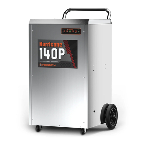
Abestorm Hurricane 140P User manual