Abit VA-11 User manual

VA-10/VA-11
Socket 462 System Board
User’s Manual
4200-0376-23
Rev. 1.01

Copyright and Warranty Notice
The information in this document is subject to change without notice and does not
represent a commitment on part of the vendor, who assumes no liability or
responsibility for any errors that may appear in this manual.
No warranty or representation, either expressed or implied, is made with respect to the
quality, accuracy or fitness for any particular part of this document. In no event shall
the manufacturer be liable for direct, indirect, special, incidental or consequential
damages arising from any defect or error in this manual or product.
Product names appearing in this manual are for identification purpose only and
trademarks and product names or brand names appearing in this document are
property of their respective owners.
This document contains materials protected under International Copyright Laws. All
rights reserved. No part of this manual may be reproduced, transmitted or transcribed
without the expressed written permission of the manufacturer and authors of this
manual.
VA-10/VA-11

Table Of Contents
Chapter 1. Introduction .................................................... 1-1
1.1. Features & Specifications....................................................... 1-1
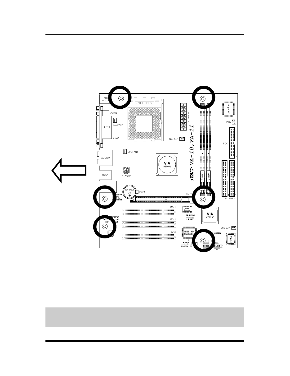
1.2. Layout Diagram...................................................................... 1-3
1.3. Jumpers & Connectors Description........................................ 1-4
Chapter 2. Hardware Setup.............................................. 2-1
2.1. Precautions ............................................................................. 2-1
2.2. Installing the System Board ................................................... 2-2
2.3. Install CPU and Heatsink ....................................................... 2-3
2.4. System Memory ..................................................................... 2-5
2.4.1. Memory Configuration Table...................................2-5
2.4.2. Installing and Removing Memory Modules............. 2-6
2.5. Connectors, Headers, and Switches ....................................... 2-7
2.5.1. ATX Power Connectors............................................ 2-7
2.5.2. FAN Connectors ....................................................... 2-8
2.5.3. CMOS Memory Clearing Header............................. 2-9
2.5.4. Accelerated Graphics Port Slot............................... 2-10
2.5.5. Front Panel Switches & Indicators Connection
Headers ................................................................... 2-11
2.5.6. Infrared Device Connection Header ....................... 2-12
2.5.7. Additional USB Port Connection Header............... 2-13
2.5.8. Additional IEEE1394 Port Headers........................ 2-14
2.5.9. Internal Audio Source Connectors .........................2-15
2.5.10. Floppy Disk Drive Connector................................. 2-16
2.5.11. IDE Disk Drive Connectors.................................... 2-17
2.5.12. External I/O Panel................................................... 2-18
Chapter 3. BIOS Setup...................................................... 3-1
3.1. Standard CMOS Features....................................................... 3-2
3.2. Advanced BIOS Features ....................................................... 3-6
3.3. Advanced Chipset Features.................................................... 3-8
User’s Manual

3.4. Integrated Peripherals........................................................... 3-13
3.5. Power Management Setup.................................................... 3-19
3.6. PnP/PCI Configurations ....................................................... 3-21
3.7. PC Health Status................................................................... 3-23
3.8. Frequency/Voltage Control .................................................. 3-25
3.9. Load Fail-Safe Defaults........................................................ 3-26
3.10. Load Optimized Defaults ..................................................... 3-26
3.11. Set Supervisor Password ...................................................... 3-26
3.12. Set User Password ................................................................ 3-26
3.13. Save & Exit Setup ................................................................ 3-26
3.14. Exit Without Saving ............................................................. 3-26
Chapter 4. Driver Installation .......................................... 4-1
4.1. Setup Items ............................................................................. 4-2
Appendix A. How to Get Technical Support ..................... A-1
VA-10/VA-11

Introduction 1-1
Chapter 1. Introduction
1.1. Features & Specifications
Processor
• Supports AMD Athlon XP Socket A Processors with 333/266 MHz
Front Side Bus
• Supports AMD K7 Athlon™ XP FSB 333/266MHz Processors
Chipset
• VIA KM400 / VT8235 chipset
• Supports Hi-Speed Universal Serial Bus (USB 2.0)
• Int. S3 UniChrome™ 2D/3D Graphics with motion compensation
• Ext. Accelerated Graphics Port connector supports AGP 8X/4X (0.8V
/1.5V)
Memory
• Two 184-pin DIMM sockets (Un-buffered Non-ECC DIMM)
• Supports 2 DIMM DDR 333/266/200 (Max. 2GB)
IEEE 1394 (For VA-11 only)
• Onboard VIA VT6307 IEEE 1394 Controller
Audio
• Onboard VIA VT1616 6-Channel AC 97 CODEC
• Professional digital audio interface supports Optical S/PDIF Out
LAN
• Onboard VIA VT6103 10/100Mbps LAN
Internal I/O Connectors
• 1x AGP slot
• 3x PCI slots
• 1x Floppy Port supports up to 2.88MB
• 2x Ultra ATA 133/100/66/33 Connectors
• 2x IEEE 1394 headers
• 1x USB 2.0 header
• 1x CD-IN, 1x AUX-IN
• 1x IrDA
User’s Manual

1-2 Chapter 1
Back Panel I/O
• 1x PS/2 Keyboard, 1x PS/2 Mouse
• 1x Serial Port connector
• 1x VGA Port connector
• 1x Parallel Port connector
• 1x Audio connector (S/PDIF Out, Center/Subwoofer, Surround
Speaker) (Front Speaker, Line-in, MIC-in)
• 4x USB Connectors
• 1x RJ-45 LAN Connector
Specifications and information contained herein are subject to change
without notice.
VA-10/VA-11

Introduction 1-3
1.2. Layout Diagram
User’s Manual

1-4 Chapter 1
1.3. Jumpers & Connectors Description
Jumpers Description Default Setting
CCMOS1 CMOS Memory Clearing Header Pins 1-2 Closed (Normal)
Connectors Description
AGP1 Accelerated Graphics Port Slot
ATX12V1 4-pin ATX12V Power Connector
ATXPWR1 20-pin ATX12V Power Connector
CD1/AUX1 Internal Audio Connectors
CPUFAN1/SYSFAN1/
AUXFAN1/NBFAN1
Fan Connectors
DIMM1/DIMM2 DDR DIMM Slots
FDC1 Floppy Disk Drive Connector
FPIO1 Front Panel Switch Connection Headers
FPIO2 Infrared Device Connection Header
FP-1394-1/FP-1394-2 Additional IEEE1394 Port Headers
FP-USB1 Additional USB Port Connection Header
IDE1/IDE2 Hard Disk Drive Connectors
PCI1/PCI2/PCI3 32bit/33MHz PCI Slots
VA-10/VA-11

Hardware Setup 2-1
Chapter 2. Hardware Setup
2.1. Precautions
Please pay attention to the following precautions before setting up any hardware.
1. Always switch off the power supply and unplug the power cord from the wall
outlet before installing the board or changing any settings.
2. Ground yourself properly by wearing a static safety wrist strap before removing
the board from the antistatic bag.
3. Hold the board by its edges. Avoid touching any component on it.
4. Avoid touching module contacts and IC chips
5. Place the board on a grounded antistatic surface or on the antistatic bag that came
with the board.
User’s Manual

2-2 Chapter 2
2.2. Installing the System Board
Before installing the system board, exam your chassis to ensure this system board fits
into it.
1. Face the side of the I/O ports toward the rear part of the chassis.
2. Locate the screw holes on the system board and the chassis base.
3. Place all the studs or spacers needed on the chassis base and have them tightened.
4. Line up all the screw holes on the board with those studs or spacers on the chassis.
5. Tightens all the screw holes.
ATTENTION: To prevent shorting the PCB circuit, please REMOVE the metal studs
or spacers if they are already secured on the chassis base and are without
mounting-holes on the system board to align with.
VA-10/VA-11

Hardware Setup 2-3
2.3. Install CPU and Heatsink
• Installing a heatsink and cooling
fan is necessary for heat to
dissipate from your processor.
Failing to install these items
may result in overheating and
processor damage.
• The AMD Socket A processor
will produce a lot of heat while
operating, so you need to use a
large heat sink that is especially
designed for the AMD socket A
processor. Otherwise, it may
result in overheating and
processor damage.
• If your processor fan and its
power cable are not installed
properly, never plug the ATX
power cable into the
motherboard. This can prevent
possible processor damage.
• Please refer to your processor
installation manual or other
documentation with your
processor for detailed
installation instructions.
This motherboard provides a ZIF
(Zero Insertion Force) Socket 462
to install AMD Socket A CPU. The
CPU you bought should have a kit
of heatsink and cooling fan along
with. If that’s not the case, buy one
specially designed for Socket A.
Please refer to the figure shown here
to install CPU and heatsink. (For
reference only. Your Heatsink &
Fan Assembly may not be exactly
the same as this one.)
User’s Manual

2-4 Chapter 2
1. Locate the Socket 462 on this motherboard. Pull the CPU release lever sideways
to unlatch and then raise it all the way up.
2. Align the CPU notch to the socket notch for CPU. Drop the processor with its pin
side down into the CPU socket. Do not use extra force to insert CPU; it only fit in
one direction. Close the CPU release lever.
3. Remove the plastic film adhesive on the heatsink. Make sure the stepped portion
of the heatsink is facing toward the end of the socket that reads “Socket 462”. Put
the heatsink faces down onto the processor until it covers the processor
completely.
4. Push down the short end of the retaining clip first to lock up with the center lug at
the bottom of the socket.
5. Use a screwdriver to insert into the slot at the long end of the retaining clip. Push
the clip downward to lock up with the center lug at the top of the socket. The
heatsink & fan assembly is now firmly attached on the CPU socket.
6. Attach the fan connector of Heatsink & Fan Assembly with the fan connector on
the motherboard.
ATTENTION: Do not forget to set the correct bus frequency and multiple for your
processor.
VA-10/VA-11

Hardware Setup 2-5
2.4. System Memory
This system board provides two 184-pin DDR DIMM slots for DDR 333 memory
modules with memory expansion size up to 2GB.
2.4.1. Memory Configuration Table
DIMM DIMM Module Total Memory
1 128MB, 256MB, 512MB, 1GB 128MB ~ 1GB
2 128MB, 256MB, 512MB, 1GB 128MB ~ 1GB
Total System Memory 128MB ~ 2GB
User’s Manual

2-6 Chapter 2
2.4.2. Installing and Removing Memory Modules
Power off the computer and unplug the
AC power cord before installing or
removing memory modules.
1. Locate the DIMM slot on the board.
2. Hold two edges of the DIMM
module carefully, keep away of
touching its connectors.
3. Align the two notch keys on the module with the two ribs on the slot.
4. Firmly press the module into the slots until the ejector tabs at both sides of the slot
automatically snaps into the mounting notch. Do not force the DIMM module in
with extra force as the DIMM module only fit in one orientation.
5. To remove the DIMM modules, push the two ejector tabs on the slot outward
simultaneously, and then pull out the DIMM module.
ATTENTION: As the static electricity can damage the electronic components of the
computer or optional modules, make sure you are discharged of static electricity by
touching a grounded metal object briefly before starting these procedures.
VA-10/VA-11

Hardware Setup 2-7
2.5. Connectors, Headers, and Switches
All the connectors, headers and switches mentioned here are depending on your
system configuration. Some features you may (or may not) have to connect or to
configure depending on the peripherals you have connected.
WARNING: Always power off the computer and unplug the AC power cord before
adding or removing any peripheral or component. Failing to so may cause severe
damage to your system board and/or peripherals. Plug in the AC power cord only after
you have carefully checked everything.
2.5.1. ATX Power Connectors
It would be recommended to supply an ATX12V power with 300W, 20A +5VDC
capacity at least for heavily loaded system, and 720mA +5VSB at least for supporting
Wake-On-LAN feature.
User’s Manual

2-8 Chapter 2
2.5.2. FAN Connectors
These 3-pin connectors each provide power to the cooling fans installed in your
system.
The CPU must be kept cool by using a powerful fan with heatsink. The system is
capable of monitoring the speed of the CPU fan.
• CPUFAN1: CPU Fan
• SYSFAN1: System Fan 1
• AUXFAN1: Auxiliary Fan 1
• NBFAN1: N.B. Chipset Fan
WARNING: These fan connectors are not jumpers. DO NOT place jumper caps on
these connectors.
VA-10/VA-11

Hardware Setup 2-9
2.5.3. CMOS Memory Clearing Header
This header uses a jumper cap to clear the CMOS memory.
• Pin 1-2 shorted (default): Normal operation.
• Pin 2-3 shorted: Clear CMOS memory.
ATTENTION: Turn the system power off first (including the +5V standby power)
before clearing the CMOS memory. Failing to do so may cause your system to work
abnormally or malfunction.
User’s Manual

2-10 Chapter 2
2.5.4. Accelerated Graphics Port Slot
This slot supports an optional AGP graphics card up to AGP 8X/4X mode. Please
refer to our Web site for more information on graphics cards.
ATTENTION: This motherboard does not support 3.3V AGP cards. Use only 1.5V
or 0.8V AGP cards.
VA-10/VA-11

Hardware Setup 2-11
2.5.5. Front Panel Switches & Indicators Connection Headers
These headers are used for connecting switches and LED indicators on the chassis
front panel. The mark “+” align to the pin in the figure below stands for positive
polarity for the LED connection.
• HLED (Pin 1, 3):
Connects to the HDD LED cable of chassis front panel.
• RST (Pin 5, 7):
Connects to the Reset Switch cable of chassis front panel.
• SPK (Pin 15, 17, 19, 21):
Connects to the System Speaker cable of chassis.
• SLED (Pin 2, 4):
Connects to the Suspend LED cable (if there is one) of chassis front panel.
• PWR-ON (Pin 6, 8):
Connects to the Power Switch cable of chassis front panel.
• PLED (Pin 16, 18, 20):
Connects to the Power LED cable of chassis front panel.
User’s Manual

2-12 Chapter 2
2.5.6. Infrared Device Connection Header
This header connects to an optional IR device attached to chassis. This motherboard
supports standard IR transfer rates.
VA-10/VA-11
This manual suits for next models
1
Table of contents
Other Abit Motherboard manuals