Abit BX6 User manual

Notice
The information in this document is subject to change without notice and
does not represent a commitment on part of the vendor, who assumes no
liability or responsibility for any errors that may appear in this manual.
No warranty or representation, either expressed or implied, is made with
respect to the quality, accuracy or fitness for any particular part of this
document. In no event shall the manufacturer be liable for direct, indirect,
special , incidental or consequential damages arising from any defect or error
in this manual or product.
Product names appearing in this manual are for identification purpose only
and trademarks and product names or brand names appearing in this
document are property of their respective owners.
This document contains materials protected under International Copyright
Laws. All rights reserved. No part of this manual may be reproduced,
transmitted or transcribed without the expressed written permission of the
manufacturer and authors of this manual.


Part No:MN-133-2A1-41 Rev:1.01
BX6 Motherboard
USER’S MANUAL
Table of Contents
Chapter 1 Introduction of BX6 Features 1-1
(1) Specifications 1-1
(2) Layout Diagram 1-3
(3) The System Block Diagram 1-4
Chapter 2 Installing the Motherboard 2-1
(1) Installing the Motherboard to the Casing 2-2
(2) Standard External Connectors 2-3
(3) Jumper and Switches 2-9
(4) Installation of the PentiumII/III, CeleronCPU 2-11
(5) Installing System Memory 2-12
Chapter 3 Introduction of BIOS 3-1
(1) CPU Setup <CPU SOFT MENU™
II> 3-3
(2) Standard CMOS Setup Menu 3-8
(3) BIOS Features Setup Menu 3-11
(4) Chipset Features Setup Menu 3-17
(5) Power Management Setup Menu 3-21
(6) PnP/PCI Configuration 3-28
(7) Load Setup Defaults 3-31
(8) Integrated Peripherals 3-32
(9) Password Setting 3-37
(10) IDE Hard Disk Detection 3-37
(11) Save & Exit Setup 3-38
(12) Exit Without Saving 3-38

Appendix A Quick Installation A-1
Appendix B General Discussion About HDD Installation B-1
Appendix C BIOS Flashing User Instructions C-1
Appendix D How to install the IDE Bus Master driver D-1
Appendix E How to install the PCI bridge driver for the 440BX chipset E-1
Appendix F Install HighPoint XStore Pro Utility F-1
Appendix G Install Winbond Hardware Doctor Utility G-1
Appendix H Technical Support H-1

Introduction of BX6 Features 1-1
Chapter 1 Introduction of BX6 Features
The motherboard is designed for a new generation CPUs. It supports the Intel
SLOT1 structure (PentiumII/III and Celeronprocessors), up to 1GB of memory,
super I/O, and Green PC functions. The motherboard provides high performance
for server systems and meets the requirements for desktop system for multimedia
in the future.
(1) Specifications
1. CPU
qCPU SOFT MENU™II eliminates the need for jumpers or DIP switches
needed to set CPU parameters
qEmploys switching type regulators to stabilize CPU operation
qSupports 66 and 100MHz MHz CPU external clock speeds
qSupports Intel®
Pentium®
III450 ~ 500MHz processor cartridge (Based on
100MHz)
qSupports Intel®
Pentium®
II 350 ~ 450MHz processor cartridge (Based on
100MHz) and Pentium®
II 233 ~ 333MHz processor cartridge (Based on
66MHz)
qSupports Intel®
Celeron®
266~433MHz processor (Based on 66MHz)
2. Chipset
qIntel®
440BX chipset (82443BX and 82371EB)
qSupports Ultra DMA/33 IDE protocol
qSupports Advanced Configuration and Power Management Interface(ACPI)
qAccelerated Graphics Port connector supports AGP 1x and 2x mode
(Sideband) 3.3V device
3. Cache Memory
qLevel 1 and Level 2 cache built into Intel®
Pentium®
II/III processor cartridge
qLevel 1 cache (without L2 cache) built into Intel®
CeleronprocessorŒ
4. Memory(System Memory)
qFour 168-pin DIMM sockets support SDRAM modules
qSupports up to 1GB
qECC support
q6 Data Buffers
5. System BIOS
qAWARD BIOS
qSupports Plug-and-Play (PnP)
qSupports Advanced Configuration Power Interface (ACPI)
qSupports Desktop Management Interface (DMI)
qYear 2000 compliant

Chapter 11-2
6.
Multi I/O Functions
qFloppy port supports up to 2.88MB, and 3 mode floppies
qUltra DMA/33 bus master IDE supports up to 4 IDE devices ( Including LS-
120 MB floppy drive )
qBuilt-in Standard/EPP/ECP parallel port connector
qTwo built-in 16550 fast UART compatible serial port connectors
qBuilt-in PS/2 keyboard and PS/2 mouse port connectors
qBuilt-in standard IrDA TX/RX header
qTwo built-in USB connectors
7.
Miscellaneous
qATX form factor
qOne AGP slot, Five PCI slots and Two ISA slots
qWake Up On LAN header
qSB-LINK header
qHardware monitoring¡GIncluded fan speed, voltages, CPU and system
environment temperature
qKeyboard Wake Up or PS/2 Mouse Wake Up (need +5VSB at least720mA)
qBoard size: 305 * 210mm
Note:
All brand names and trademarks are the property of their respective owners.
ŒThe actual specs of Intel®
Celeron®
processor will depend on Intel’s shipping specs.
¯Above 66MHz/100MHz bus speed supported but not guaranteed due to the PCI and chipset
specs.
¯Sound Blaster™
is a registered trademark of Creative Technology Ltd.in the United States
and certain other countries. Sound Blaster - LINK™
and SB-LINK™are trademarks of
Creative Technology Ltd.
¯Specifications and information contained in this manual are subject to change without
notice.

Introduction of BX6 Features 1-3
(2) Layout Diagram
Figure 1-1 Motherboard Component Locations

Chapter 11-4
(3) The System Block Diagram

Installing the Motherboard 2-1
Chapter 2 Installing the Motherboard
This BX6 motherboard not only provides all standard equipment for classic
personal computers, but also provides great flexibility for meeting future upgrade
demands. This chapter will introduce step by step all the standard equipment
and will also present, as completely as possible, future upgrade capabilities. This
motherboard is able to support all IntelPentiumII/III processors and Intel
Celeronprocessor now on the market. (For details, see specifications in
Chapter 1.)
This chapter is organized according the following features:
(1) Installing the Motherboard to the Casing
(2) Standard external connectors
(3) Jumpers and switches
(4) Installation of the PentiumII/III, CeleronCPU
(5) Installing the system memory
NNNN
Before proceeding with the installation
Before installing the motherboard please be sure to turn off or disconnect the
power supply unit. Before making any modifications to the hardware
configuration of the motherboard, the power supply to any areas of the
motherboard you plan to modify should be turned off to avoid unnecessary
damage to the hardware.
&
User friendly instructions
Our objective is to enable the novice computer user to perform the installation by
themselves. We have attempted to write this document in a very clear, concise
and descriptive manner to help overcome any obstacles you may face during
installation. Please read our instructions carefully and follow them step-by-step.

Chapter 22-2
(1) Installing the Motherboard to the Casing
Most computer cases will have a base on which there will be many mounting
holes that allows the motherboard to be securely attached and at the same time,
prevents short circuits.
There are two ways to attach the motherboard to the base.
lwith spacers
lor with bolts
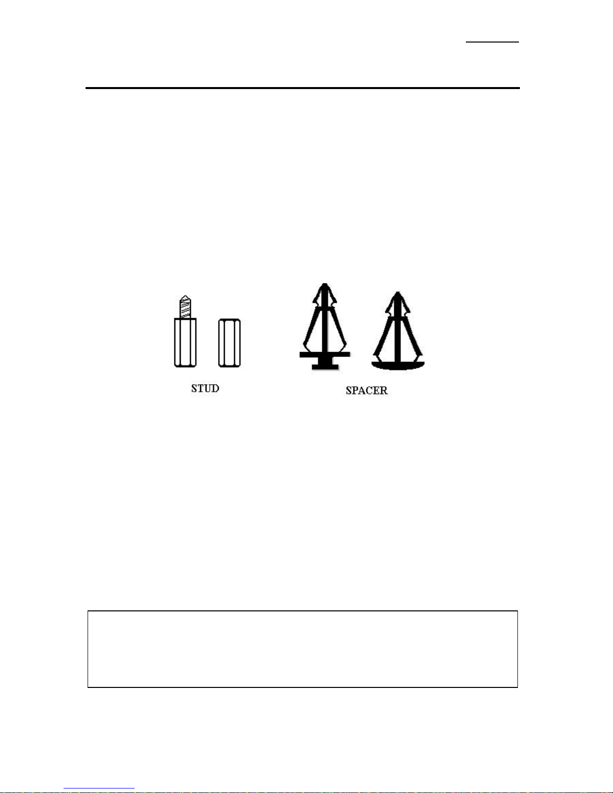
Please refer to the figure below that shows the studs and spacers, they may have
several types, but all look like the figures below:
Figure 2-1. The outline of stud and spacer
In principle, the best way to attach the motherboard is with bolts, and only if you
are unable to do this should you attach the board with spacers. Take a careful look
at the motherboard and you will see many mounting holes on it. Line these holes
up with the mounting holes on the base. If the holes line up, and there are screw
holes this means you can attach the motherboard with bolts. If the holes line up
and there are only slots, this means you can only attach the motherboard with
spacers. Take the tip of the spacers and insert it into the slots. After doing this to
all the slots, you can slide the motherboard into position aligned with the slots.
After the motherboard has been positioned, check to make sure everything is OK
before putting the casing back on.
Note: If the motherboard has mounting holes, but don’t line up with the holes on the base and
their are no slots to attach the spacers, don’t worry, you can still attach the spacers to
the mounting holes. Just cut the spacers (along the dotted line) (the spacer may be a
little hard so be careful of our hands). In this way you can still attach the motherboard
to the base without worrying about short circuits.

Installing the Motherboard 2-3
(2) Standard External Connectors
Inside the case of any computer several cables and plugs have to be connected.
These cables and plugs are usually connected one-by-one to connectors located
on the motherboard. You need to carefully pay attention to any connection
orientation the cables may have and, if any, notice the position of the first pin of
the connector. In the explanations that follow, we will describe the significance
of the first pin.
PN1(Pin 1-2-3-4-5): Keylock and Power LED Header
There is a specific orientation for pin 1 through pin 5. Insert the two-threaded
keylock cable into pin 4 and pin 5, and three-threaded power LED cable to Pin 1
~ pin 3. Check to make sure the correct pins of connector on the motherboard.
Pin number Name or significance of signal Connector Name
1+5VDC
Power LED
2No connection Power LED
3Ground Power LED
4Keyboard inhibit Signal Keylock
5Ground Keylock
PN1(Pin 7-8): HDD LED Header
Attach the cable from the case’s HDD LED to this connector.
Pin number Name or significance of signal
7
LED power
8
HDD active

Chapter 22-4
PN1 (Pin 10-11): Power Switch Header
Pin number Name or significance of signal
10 Power On/Off switch
11 Ground
PN1 (Pin 13-14): Hardware Suspend Switch (SMI Switch) Header
Attach the cable from the case’s suspend switch (if there is one) to this switch.
Use this switch to enable/disable the power management function by hardware.
Pin number Name or significance of signal
13 Vcc
14 Suspend signal
PN2(Pin 1-2): Hardware Reset Header
Attach the cable from the case’s Reset switch to this connector. Press and hold the
reset button for at least one second to reset the system.
Pin number Name or significance of signal
1Reset input
2Ground
PN2(Pin 4-5-6-7): Speaker Header
Attach the system speaker to connector PN2.
Pin number Name or significance of signal
4+ 5VDC
5Ground
6Ground
7Speaker data
PN2(Pin 9-10): Suspend LED Header
Pin number Name or significance of signal
9LED power
10 Suspend LED active

Installing the Motherboard 2-5
KM1 MOUSE: PS/2 Mouse Connector
Attach a PS/2 mouse to this 6-pin Din-connector.
Pin number Name or significance of signal
1Mouse data
2No connection
3Ground
4+5VDC
5Mouse clock
6No connection
KM1 KB: PS/2 Keyboard Connector
Attach a keyboard to this 6-pin Din-connector.
Pin number Name or significance of signal
1Keyboard data
2No connection
3Ground
4+5VDC
5Keyboard clock
6No connection

Chapter 22-6
CONT1: ATX Power Input Connector
Caution: If power supply connectors are not properly attached to ATXPWR, the power
supply or add-on cards may be damaged.
Attach the connectors from the power supply to CONT1.
Pin number Name or significance of signal
1+3.3VDC
2+3.3VDC
3Ground
4+5VDC
5Ground
6+5VDC
7Ground
8Power Good
9+5VSB
10 +12VDC
11 +3.3VDC
12 -12VDC
13 Ground
14 On/Off control signal
15 Ground
16 Ground
17 Ground
18 -5VDC
19 +5VDC
20 +5VDC
FAN1, FAN2, FAN3 (CPU FAN)
Pin number Name of the signal or signification
1Ground
2+12V
3Sense signal

Installing the Motherboard 2-7
IR1: IR Header (Infra-red)
Pin number Name or significance of signal
1+5V
2No connection
3IR_RX
4Ground
5IR_TX
I/O Port Connectors
Name Pin number Description
IDE1 40 IDE channel 1 connector
IDE2 40 IDE channel 2 connector
FDC 34 Floppy disk connector
LPT 25 Parallel port
COM1 9Serial port COM1 connector
COM2 9Serial port COM2 connector
USB 8Universal serial Bus
Notes: *IDE1, IDE2 are high performance PCI IDE connectors. Up to four IDE interface
devices are supported.
WOL1: Wake On LAN Header
Pin number Name or significance of signal
1+5VSB
2GND
3Sense input
SB1: SB-Link™
Header
Pin number Name or significance of signal
1GNTA
2Ground
3KEY
4REQA
5Ground
6SERIRQ

Chapter 22-8
RT2 Header (Optional)
This header is for you to connect an additional thermistor to detect the CPU
temperature. You can buy the thermistor at an electronics store, and ask for a
10KΩthermistor which will be OK. Please don’t use too long of a lead wire for
the thermistor. You can see the detected temperature in the BIOS menu. (see
Chipset Features Setup Menu)
According to ACPI specifications, CPU fan speed is relative to the CPU
temperature. In order to avoid confusing ACPI functions, we strongly suggest that
you connect the additional thermistor to the CPU.
Note: Before you install or unplug any connectors or add-on cards, please remember to turn
the ATX power supply switch off (fully turn the +5V standby power off), or take power
cord off. Otherwise, you may cause the motherboard components, add-on cards to
malfunction or be damaged.

Installing the Motherboard 2-9
(3) Jumper and Switches
You can set jumper switches on the motherboard to configure various hardware
options. See Figure 1-1 for jumper locations.
Throughout this section, the following symbols are used to indicate jumper
settings.
For 3-pin jumpers, the symbols below are used:
For 2-pins jumpers, the following symbols are used:
Note: To avoid losing jumper caps, attach the removed jumper cap to one of the jumper pins.
Short Pins 1 and 2 with a jumper cap.
Short Pins 2 and 3 with a jumper cap.
Place the jumper cap over the two pins of the
jumper to Short the jumper.
Remove the jumper cap to Open the jumper cap.

Chapter 22-10
CCMOS 1 : CMOS Discharge Jumper
Jumper CCMOS discharge CMOS memory. When you install the motherboard,
make sure this jumper is set for Normal Operation (1-2). See the jumper below.
Setting CCMOS
Normal Operation
(Default)
Discharge CMOS
Note: Before you clear the CMOS, you have to turn the power off first (including the +5V
standby power). Otherwise, your system may work abnormally or malfunction.

Installing the Motherboard 2-11
(4) Installation of the Pentium
II/III, Celeron
CPU
The installation method for the CPU is printed on the package of the retention
mechanism that comes with the motherboard. You can refer to it while you install
the CPU. This motherboard also supports the Celeron®
PPGA processor. If you
want to install the Celeron®
PPGA processor, you have to use an additional
adapter that allows you to use a Celeron®
PPGA processor in a slot 1 board. For
this ABIT makes the SlotKETadapter.
Note:
lInstalling a heat sink and cooling fan is necessary for proper heat dissipation from your
CPU. Failing to install these items may result in overheating and damage of your CPU.
lPlease refer to your boxed processor installation or other documentation attached with
your CPU for detailed installing instructions.

Chapter 22-12
(5)
Installing System Memory
The motherboard provides four 168-pin DIMM sites for memory expansion.. The
DIMM socket supports 1Mx64(8MB), 2Mx64(16MB), 4Mx64(32MB),
8Mx64(64MB), 16Mx64(128MB), and 32Mx64(256MB) or double sided DIMM
modules. Minimum memory size is 8MB and maximum memory size is 1GB
SDRAM.
There are four Memory module sockets on the system board.(Total eight banks)
In order to create a memory array, certain rules must be followed. The following
set of rules allows for optimum configurations.
lThe memory array is 64 or 72 bits wide. (Without parity or with parity)
lThose modules can be populated in any order.
lSupport single and double density DIMMS.
The following is the valid memory configuration:
Bank Memory Module Total Memory
Bank 0, 1
(DIMM1) 8MB, 16MB,32MB,
64MB, 128MB, 256MB 8MB ~ 256MB
Bank 2, 3
(DIMM2) 8MB, 16MB,32MB,
64MB, 128MB, 256MB 8MB ~ 256MB
Bank 4, 5
(DIMM3) 8MB, 16MB,32MB,
64MB, 128MB, 256MB 8MB ~ 256MB
Bank 6, 7
(DIMM4) 8MB, 16MB,32MB,
64MB, 128MB, 256MB 8MB ~ 256MB
Total System Memory 8MB ~ 1GB
Other manuals for BX6
1
Table of contents
Other Abit Motherboard manuals

Abit
Abit Fatal1ty F-I90HD User manual

Abit
Abit BX133-RAID User manual

Abit
Abit BX133-RAID User manual

Abit
Abit KT7 User manual

Abit
Abit AB-CX6 User manual

Abit
Abit Fatal1ty AA8XE User manual

Abit
Abit IC7-MAX3 User manual

Abit
Abit AMD ATHLON KV8 PRO User manual

Abit
Abit IL9 Pro User manual

Abit
Abit AN9 32X User manual