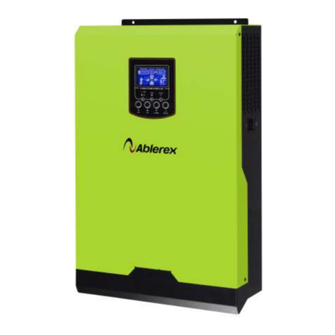
Ablerex EnerSolis ES3000T User manual

VERSION 0.1
Ablerex Grid-Tied PV Inverter
EnerSolis Series
ES3000T / ES3680T
ES4000T / ES4600T
ES5000T / ES5500T
User Manual
1
Table of Contents
Introduction ............................................................................................................. 2
Safety Instructions .................................................................................................. 3
1. Introduction......................................................................................................... 6
1.1 External Dimensions ................................................................................. 6
1.2 Equipment Description .............................................................................. 7
2. Installation .......................................................................................................... 8
2.1 Unpacking .................................................................................................. 8
2.2 Installation site requirements .................................................................... 9
2.3 Mounting the unit ..................................................................................... 11
2.4 Electrical Installation ............................................................................... 13
2.5 Connecting to the Grid (AC utility) ......................................................... 16
2.6 PV Array Input Wiring ............................................................................. 20
3. 2.9" Panel ......................................................................................................... 23
3.1 Functions of the 2.9" Panel..................................................................... 23
3.2 Display and Operation of 2.9" Panel Measurement Messages ........... 25
3.3 Status Display of the 2.9" Panel PV Inverter ......................................... 30
3.4 Setup Mode of the 2.9" Panel PV Inverter............................................. 31
4. Communication Ports ...................................................................................... 34
4.1 Standard Communication Ports ............................................................. 34
4.2 Optional Communication Interface Card ............................................... 35
5. PV Inverter Troubleshooting and Solutions ................................................... 39
6. Specification Table .......................................................................................... 42

2
Introduction
Thank you for purchasing EnerSolis Grid-Tied PV Inverter.
We are a specialized manufacturer of power equipment, with
years of experience in development and production. We hope that
this equipment will facilitate smooth and error-free operation of
your solar system for years to come. However, a power system
with PV inverter is a complicated system and failures may occur. If
you encounter any errors or malfunctions in the PV inverter or
system, please call us or the local distributor. We will provide
prompt assistance to solve your problems.
Please read this user manual carefully to ensure quick and
correct installation of the equipment.
3
Safety Instructions
Please read all the installation instructions in
this EnerSolis user manual before installing or
maintaining your system.
The PV inverter should be opened by qualified electrical
technicians only.
When the photovoltaic array is exposed to light, it
supplies a d.c. voltage to the PV Inverter.
CAUTION:
Maintenance of EnerSolis should be performed by
qualified electrical technicians, and only after all AC and
DC power are completely disconnected from EnerSolis.
EnerSolis must be disconnected from the utility and
make sure that there is no accidental connection with the
utility. The PV array must also be disconnected
with EnerSolis.
CAUTION:
As EnerSolis has a built-in high voltage capacitor, fatal
high voltage remains in the inverter for some time after
it is shut down.

4
After the inverter is shut down and the utility and the PV
array are disconnected from EnerSolis, please wait for
the internal capacitor to discharge before opening the
unit for maintenance.
Warnings
Description of warning symbols:
Symbol Description
Caution! Risk of electric shock!
Caution! Danger!
Caution! High Temperature on Surface!
The enclosure surface temperature of PV
inverter may exceed +70 °C.
Caution! Risk of electric shock!
Residual energy release time!
Please refer to the user manual.
10min
5
Repair and Maintenance
PV inverter should be repaired by trained electrical
technicians only.
PV Array
When installing and configuring the PV array, make sure
that the PV array's rated voltage parameters which provided by
the manufacturer could meet the applicable specifications.
Make sure the open-circuit voltage of the PV array under
intensive sun, with ambient temperature of -13°F (-25°C), does
not exceed maximum withstanding voltage of EnerSolis
(500Vdc). Voltage exceeding 500Vdc will cause permanent
damage to PV inverter.
Grid connection
Only the distributor whom has a licensed electrical
engineer can install the PV inverter. To install and operate to
the grid require the permission from the local power company.
Please contact your local distributor for installation details.

6
1. Introduction
1.1 External Dimensions
Product Model No.
Dimensions (mm)
ES3000T / ES3680T
ES4000T / ES4600T
ES5000T / ES5500T
H 539
W 469
D 157
7
1.2 Equipment Description
1. LCD panel and LED indicators: Shows PV inverter
operation information and status.
2. DC input terminals: The input connections of PV array.
3. Standard communicationports: RS485, EPO.
4. Optional communication expansion slots: USB, Dry contact,
TCP/IP, and Wi-Fi.
5. AC output terminal: PV inverter transmit the AC power to
the utility.
4
5
2
3
1

8
2. Installation
Please read the safety instructions carefully before the PV
inverter installation.
2.1 Unpacking
Although the manufacturer has designed robust
packaging for the product, still the damages may occur during
the shipment. When you received your PV inverter, please
check them carefully. If there is any damage, please notify
your local distributor. (Packaging container can be recycled
and reused.)
Take out the PV inverter from the carton and check the
package content. Standard accessories include:
Two accessory packs.
A data disc
A wall mount kit set (include two wall mounting
brackets and a backplate position paper).
9
2.2 Installation site requirements
When selecting an installation location and method, be
sure to take the weight of the PV inverter into account.
An appropriate installation location will optimize system
performance, reduce the chances of malfunctions, and
extend the product lifetime. Please follow the guidelines
below for an appropriate location.
PV inverter are designed for outdoor use, with protection
class IP65, and can be installed outdoors and in wet
environments. Power generation capacity of the PV inverter
varies due to ambient temperature, humidity, and installation
location. Recommend locations shall out of direct sunlight,
with ambient temperatures between the recommended
operating temperatures.
ES3000T
ES3680T
ES4000T
ES4600T
ES5500T
-25 °C
~
+50 °C
-25 °C
~
+45 °C
The PV inverter should be hung perpendicularly against
the wall. Please make sure that the wall mounting location
-25 C 50 C
0%~90%
45 C/

10
does not cause the PV inverter to tilt forward or backward
during installation.
When choosing an installation site, ensure that there is
enough space for the PV inverter to dissipate the heat
generated during operation. Please see the diagram
below for recommended heat dissipation space.
20cm
20
cm
20
cm
20cm
5
cm
11
2.3 Mounting the unit
It is recommended to use the enclosed backplate to
mount the PV inverter on the wall. When selecting an
installation location, be sure to consider whether it can
withstand the weight of PV inverter. It is recommended to
install the unit vertically on a solid concrete or a brick wall.
Wall Mount

12
2.3.1 Installation steps
Method I: Use the wall mounting brackets to fix the unit.
Step 1: Put the backplate position paper on the intended
spot of the wall. Drill holes based on the diameter
of the backplate to fix holes. Finally, fix the
backplate on the wall.
Step 2: Hang the PV inverter on the brackets. Make sure
the inverter holds firm and securely.
Inv erter
13
Method II: Use screws to fix the unit.
Step 1: As shown in the figure below, drill holes on the
wall at the marked distances and fasten the
screws to the drilled holes.
Step 2: Mount the PV inverter on the wall. Make sure the
unit is installed securely and not slanted.

14
2.4 Electrical Installation
CAUTION:
Maintenance of EnerSolis should be performed by
qualified electrical technicians, and only after all AC and
DC power are completely disconnected from EnerSolis.
Make sure the AC circuit breaker has been installed
between the PV inverter and the utility.
Note: The Ue: 240Vac / Ie: 30A circuit breaker is
recommended.
Make sure the DC circuit breaker has been installed
between the PV inverter and the PV array.
Note: The Ue:600Vdc / Ie: 20A circuit breaker is
recommended.
The AC and DC circuit breaker must be disconnected
during installation process.
During installation, make sure that both the AC and DC
circuit breakers are turned off.
15
The wiring of the PV inverter is shown in Figure
1.Detailed installation steps for AC output and PV array input
are explained in the following sections.
Figure 1

16
2.5 Connecting to the Grid (AC utility)
CAUTION:
An AC circuit breaker should be installed between the
PV inverter and the utility before wiring the unit to the
utility.
Step 1: Make sure that the utility voltage and utility frequency
meet the specifications of the PV inverter.
Step 2: Make sure the circuit breaker which connected to the
utility is opened before installed the PV inverter’s AC
output. The AC circuit breaker should be closed only
after completed the electrical installation of the PV
inverter.
Step3: As shown in Figure 2, remove the cover of AC
output. Follow the steps in Figure 3 to set the AC
output wiring by using the recommended wire
diameter. You can follow the instructions in Figure 4 to
adopt different wiring methods for the desired output
voltage.
17
Figure 2
Figure 3

18
Figure 4
Step 4: Fasten the AC output water-proof cover securely, as
shown in Figure 5.
Figure 5
19
To prevent electric shock hazard, make sure the ground of
the PV inverter is connected to the ground properly before
any operation.
Recommended wire diameter for AC cable
Model Diameter Φ(mm)
Area (mm2) AWG no.
ES3000T / ES3680T
>2.05 >3.5 >12
ES4000T / ES4600T
ES5000T / ES5500T
≥2.59 ≥5.5 ≥ 10

20
2.6 PV Array Input Wiring
The PV inverter is equipped with specific quick installation
terminals for PV array, as shown in Figure 6.
Figure 6
2.6.1 Precautions of PV Array Configuration
The number and connection of the PV modules have to
meet the PV inverter specifications and the following three
requirements:
1 To prevent damage to the PV inverter, make sure that the
maximum open-circuit voltage (Voc) less than500Vdc in
each PV array. Voltage exceeding 500Vdc will cause
permanent damage to the PV inverter.
2 Maximum short circuit current (Isc) for each PV array
should less than the maximum input current which
specified on PV inverter.
3 The maximum power voltage for the PV array should
remain within the maximum power tracking range under
any kind conditions.
21
2.6.2 Installation steps for PV array input
CAUTION:
An independent DC circuit breaker shall be installed
between the inverter and the PV array before the PV
inverter is connected to the PV array.
Follow the steps below for connecting of the PV array to
the PV inverter:
Step 1: Ensure the correct polarity of the PV array, and
the voltage less than the PV inverter's maximum
input voltage (500Vdc).
Step 2: Connect the PV array's positive polarity to the PV
inverter's positive terminal.
Step 3: Connect the PV array's negative polarity to the PV
inverter's negative terminal.
Step 4: For a multi-string PV array, repeat Steps 1 to
Steps 3.
Step 5: Cover up other unused terminals on the PV
inverter with the protective lids to avoid potential
electric shock.
Recommended wire diameter for PV array input
Model Diameter Φ(mm)
Area (mm2) AWG no.
ES3000T / ES3680T
>2.05 >3.5 >12
ES4000T / ES4600T
ES5000T / ES5500T
≥2.59 ≥5.5 ≥ 10

22
PV Array Wiring Methods
1. Standard mode: Two strings that each of them in
different numbers of PV array can be configured
independently, as shown in Figure 7.
Figure 7
2. Parallel Mode: A single-string PV array is connected to
String A and String B. It should be configured in the
Setup Mode, as shown in Figure 8. (See Section 3.4 for
details of the Setup Mode.)
Figure 8
23
3. 2.9" Panel
3.1 Functions of the 2.9" Panel
Panel symbols described below the table:
(1) LCD screen
Symbol Description
The PV inverter is operating in Special Mode
Grounding fault, or DC-
input insulation impedance too
low
Utility
PV array
PCS PV inverter
LOAD PV inverter power generation indication
5
8
6
7
1
2
3
4

24
The operation process chart
, showing the relationship
between the PV inverter, PV array input
, and AC output
power
Measured value of the PV inverter
LED indicators
(2)
Red LED on indicates some errors occurred in PV
inverter
(3)
Yellow LED on indicates the
electrical conditions
exceeding the PV inverter’s allowable operating range
(4)
Green LED on or flashing indicates that energy
generation by the solar panel is greater or less than the
value of PV inverter's sleeping power
Buttons
(5) Setup /Query
(6) Previous page
(7) Next page
(8) Confirm Setup changes
25
3.2 Display and Operation of 2.9" Panel
Measurement Messages
When the PV inverter starts, all the LED indicators and
all the LCD screen 's symbols are on, as shown in Figure A.
The following information describes various electrical
parameters shown up on the LCD screen when the inverter is
in operation. Use the▲ and ▼keys to navigate between the
pages. The general views of displayed messages are shown
as follows.
3.2.1 String A input voltage, as shown in Figure B.
3.2.2 String B input voltage, as shown in Figure C.
A
B
C

26
3.2.3 String A input current, as shown in Figure D.
3.2.4 String B input current, as shown in Figure E.
3.2.5 String A input power, as shown in Figure F.
3.2.6 String B input power, as shown in Figure G.
3.2.7 Output voltage, as shown in Figure H.
D
E
F
G
H
27
3.2.8 Output frequency, as shown in Figure I.
3.2.9 Output current, as shown in Figure J.
3.2.10 Output power, as shown in Figure K.
3.2.11 Total energy generation, as shown in Figure L.
I
J
K
L

28
3.2.12 When the total energy generation exceeds 10,000
KWH, the information will be displayed alternately. For
example, when the total energy generation was
999,999 KWH, as shown in Figures L1 and L2.
3.2.13 The enclosure surface temperature can be displayed
in Celsius or Fahrenheit, as shown in Figures M1 and
M2.
M1
M2
L1
L2
29
3.2.14 Heat sink temperature can be displayed in Celsius
or Fahrenheit, as shown in Figures N1 and N2.
N1
N2

30
3.3 Status Display of the 2.9" Panel PV
Inverter
When the voltage of the PV array exceeds 120Vdc, the
PV inverter starts running automatically.
The following table describes various PV inverter’s
operation mode:
Mode
LCD screen display
Description
Power
generation
When the voltage of the PV array is
between 120Vdc and 500Vdc, the
PV inverter is in the power
generation mode, indicated by a
long light green LED.
Standby
When the voltage of the PV array is
below 120Vdc, the PV inverter is in
standby mode, indicated by flashing
green and yellow LED individually.
Fault
Electrical conditions exceeding the
PV inverter’s allowable operating
range are indicated by the
corresponding alarm codes and
a flashing yellow LED.
PV inverter failures or malfunctions
are indicated by the corresponding
error codes and a flashing red LED.
EPO
Emergency power off. When the
user short-circuit the EPO terminal,
the PV inverter will stop output
immediately and remains in s
tandby
mode. It indicated by a flashing red
LED.
Shutdown
When PV array cannot generate
enough energy (such as at night or
in rainy days), the PV inverter will
automatically shutdown to stop
output.
31
3.4 Setup Mode of the 2.9" Panel PV
Inverter
Precautions of PV Inverter Setup:
a Make sure that the PV inverter is disconnected from the
utility.
b Only the well trained professional electrical technicians
could be allowed to manipulate the PV inverter on site..
c In Setup mode, it can change country code setting,
standard or parallel mode for the PV array, and the unit
ID number.
d Please change the settings as needed. Do not alter the
remaining settings to avoid PV inverter malfunctioning.
Follow the steps below to make changes in Setup mode:
Step 1: To enter the Setup mode, press both the ▲ and
▼keys on the panel simultaneously for about five
seconds.
Step 2: In the setup mode, set the country code first. The
screen displays SET and country code alternately,
as shown in Figures O1 and O2. Use the ▲ and ▼
keys to change the country code.
CAUTION:
Do not change the country code unnecessarily, it result
the PV inverter may not working properly.

32
Note:
The country codes are listed as follows
de / Germany es
/ Spain it
/ Italy
fr / France be
/ Belgium tw
/ Taiwan
usa
/ U.S.A pt
/ Portugal au
/ Australia
gb / U.K. cz
/ Czech gr
/ Greece
nl / Holland sl
/ Slovenia at
/ Austria
jp / Japan ch
/ China kr
/ Korea
ec / custom
Step 3: Press the key to set the standard or parallel
mode for the PV array. Use the ▲ and ▼ keys to
switch to either standard or parallel mode, as shown
in FiguresP1 and P2.
Note:
STD: Standard Mode ; PAR: Parallel Mode
P1
P2
O1
O2
33
Step 4: Press the key to set the ID number of the PV
inverter. The panel now shows the SET and
ID setting alternately, as shown in Figures O1 and Q.
Use the ▲ and ▼ keys to set the ID number as
needed.
CAUTION:
Do not change the ID setting unnecessarily, it will result
the monitoring software’s communication abnormal.
Step 5: Press the key to exit the Setup mode. The
screen now displays SAVE, as shown in Figure R.
Step 6: Wait until the changes are saved, then restart the PV
inverter.
Q
R

34
4. Communication Ports
4.1 Standard Communication Ports
4.1.1 RS485 communication port definition
The RS-485 communication port setting is shown
as follows:
Baud rate 9600 bps
Data length 8 bits
Stop bit 1
Parity None
Pin definitions for RS-485:
4.1.2 EPO (Emergency Power Off) RJ45
Connector
User can short-circuit Pin 4 and Pin 5 to force the PV
inverter shutdown immediately.
Note:
Make sure the wiring of the RJ45 connector is
correct.
EPO is intended for system emergency power off.
The operating PV inverter can be stopped
immediately and remains in standby mode. by
shorting the circuit with the pins which specified in
the right figure.
PIN 1:Reserve
PIN 2:Reserve
PIN 3:485 GND
PIN 4:EPO GND
PIN 5:EPO
PIN6:Reserve
PIN 7:485 A/Data+
PIN 8:485 B/Data-
35
4.2 Optional Communication Interface Card
4.2.1 Hardware Installation Instructions
CAUTION:
Risk of electric shock!
Please disconnect the DC circuit breaker and AC
circuit breaker first, and make sure the PV inverter is
powered off. Follow the steps and the figures below to
install the communication interface card.
Insert the communication
interface card into the slot
and wiring it properly.
Remove the 4 screws on the
waterproof lid.

36
4.2.2 USB card
a. CN2 is for USB connectors.
b. Compliant with USB 1.0 version, which transmission
rate can up to1.5Mbps.
c. Compliant with USB HID 1.0 (Human Interface Devices)
version.
d. Pin Definitions:
Fasten the 4 screws back to the
waterproof lid.
PIN1:VCC (+5V)
PIN2:D-
PIN3:D+
PIN4:Ground
37
4.2.3 Relay Junction Card (DCE-B)
a. Pin definitions for the terminals:
1
2
3
4
5
6
7
8
PIN 1: Utility voltage is too high or too low.
PIN 2: The input voltage for the maximum power tracker A or B
is within the rated range.
PIN 3: The input voltage for the maximum power tracker A or B
is too high or too low.
PIN 4: The frequency of utility voltage is too high or too low.
PIN 5: Islanding effect.
PIN 6: A over current situation in the PV inverter.
PIN 7: The heat sink temperature of the PV inverter is too high.
PIN 8: Common point.
b. Contact capacity of each relay is 40dc/25mA.
c. JP1~5 is for selection of the relay contact action:
PIN 1&2 short-circuit is for N.C. action.
PIN 2&3 short-circuit is for N.O. action.

38
4.2.4 TCP/IP Card
User can use the TCP/IP card to communicate and
monitor the PV inverter via external devices. See
TCP/IP (Ethernet) card user manual for details.
4.2.5 Wi-Fi Card
User can use the Wi-Fi card to communicate and
monitor the PV inverter via external devices. See
Wi-Fi card user manual for details
39
5. PV Inverter Troubleshooting and
Solutions
Error or Alarm Codes are displayed automatically on the
LCD screen of the PV inverter. See Tables 1 and 2 below for its
explanations.
Table 1:Description of PV inverter error and alarm codes
LCD
Display
Cause Description Solution
ER00
DC_BUS
charging
abnormal
During DC boot process,
DC_BUS failed to reach
the setting value.
1. Disconnect the PV array
from the PV inverter.
2. Wait until the LCD monitor
is completely off.
Then reconnect the PV
array to the PV inverter.
3. If the problems persist,
please contact your local
distributor.
ER02 Slave MCU errors
Slave MCU failed to
work normally.
ER07 DC_BUS voltage
too high DC_BUS voltage is
higher or lower than
rated value during
operation.
ER08 DC_BUS voltage
too low
ER12
DC_BUS
charging
abnormal
Prior to connecting to the
utility, DC_BUS fails to
reach the setting value.
ER17 EEPROM error Unable to
access EEPROM
ER22 Output relay
abnormal
PV inverter’s output relay
is abnormal.
ER24
Output current
detection
abnormal
System detected the
output current abnormal
during DC boot process.
ER25 String A input
over current Input current exceeds
rated current.
ER26 String B input
over current
This manual suits for next models
5
Table of contents
Other Ablerex Inverter manuals
Popular Inverter manuals by other brands

Fenner
Fenner QD:E Series Installation and operating instructions

PrimeVOLT
PrimeVOLT PV 4K6HB-60 user manual

Rich electric
Rich electric Invertek SuperCombi SC-1500-12X user manual

Keysight Technologies
Keysight Technologies E4360A Service guide

AEROCOMPACT
AEROCOMPACT CompactGROUND GS10plus Assembly instructions

Victron energy
Victron energy EasyPlus manual

Generac Power Systems
Generac Power Systems IM Series owner's manual

Benning
Benning Tebevert III Operation and maintenance manual

Sterling Power
Sterling Power Pro Combi S+ 1600 Series manual

Kohler
Kohler 6EKOD Operation manual

Dynamo Power
Dynamo Power DP7100 owner's manual

Mosa
Mosa GE 35 PS Use and maintenance manual