Abov AT3212U User manual

Contents AT3212U Demo board quick start guide
2
Contents
1Introduction ....................................................................................................................................4
2User requirements..........................................................................................................................5
2.1 Hardware.............................................................................................................................5
2.1.1 I2C to UART Board.................................................................................................5
2.1.2 Touch Demo Board.................................................................................................5
2.2 Software ..............................................................................................................................6
2.3 Reference documents .........................................................................................................6
2.4 System requirements ..........................................................................................................7
2.5 ABOV website .....................................................................................................................7
3Building and running project ..........................................................................................................8
3.1 Prepare the I2C to UART Board and Touch Demo Board ..................................................9
3.1.1 Hardware components of the I2C to UART Board .................................................9
3.1.2 Hardware components of the Shield Board..........................................................10
3.2 Set up the I2C to UART Board and Touch Demo Board ...................................................11
3.2.1 Set jumpers to control the I2C to UART Board ....................................................11
3.2.2 Connect to the I2C to UART Board to use the Touch Demo Board .....................12
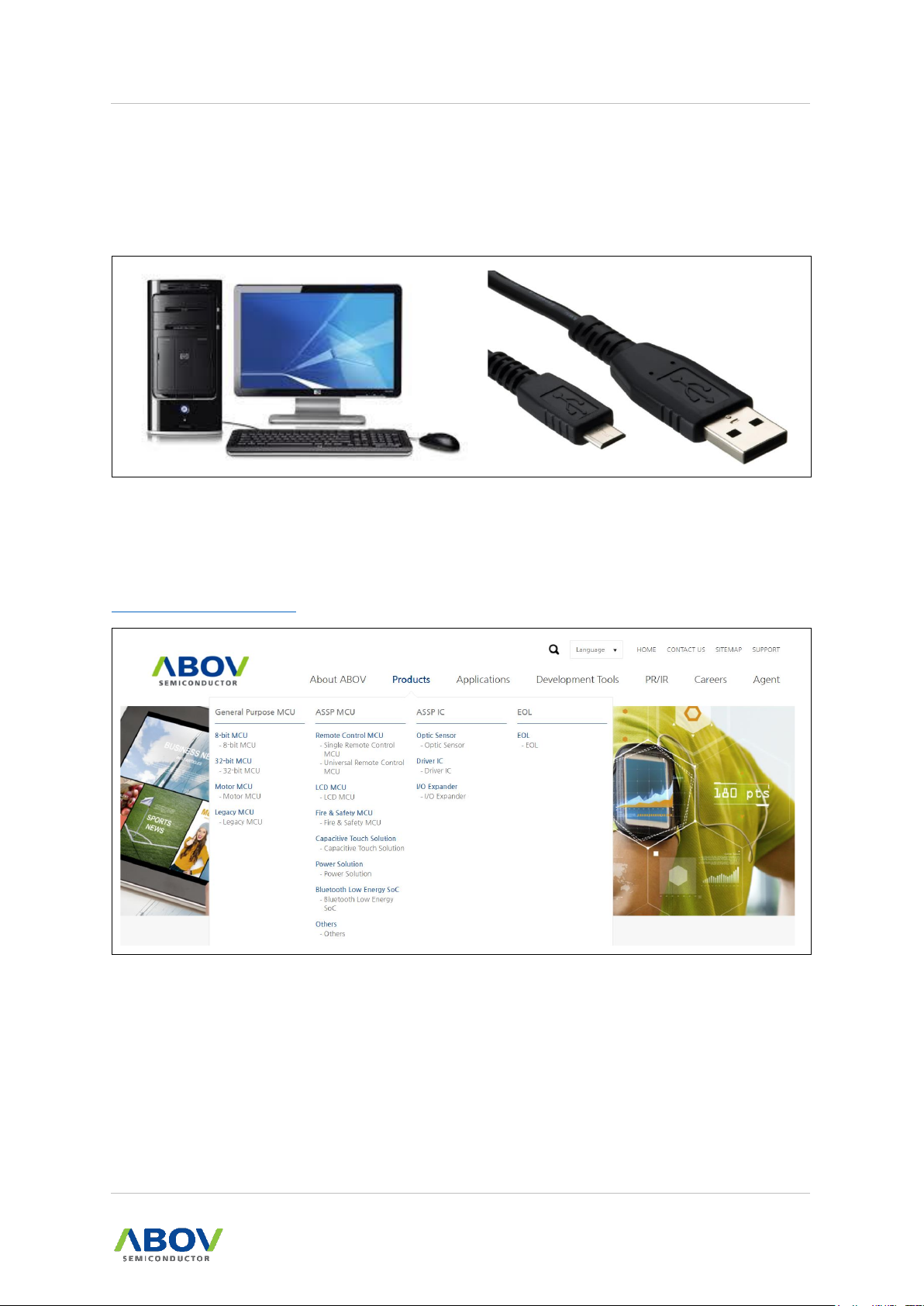
3.3 Connect the I2C to UART Board to your PC.....................................................................13
3.3.1 Connect PC via USB on the I2C to UART Board .................................................13
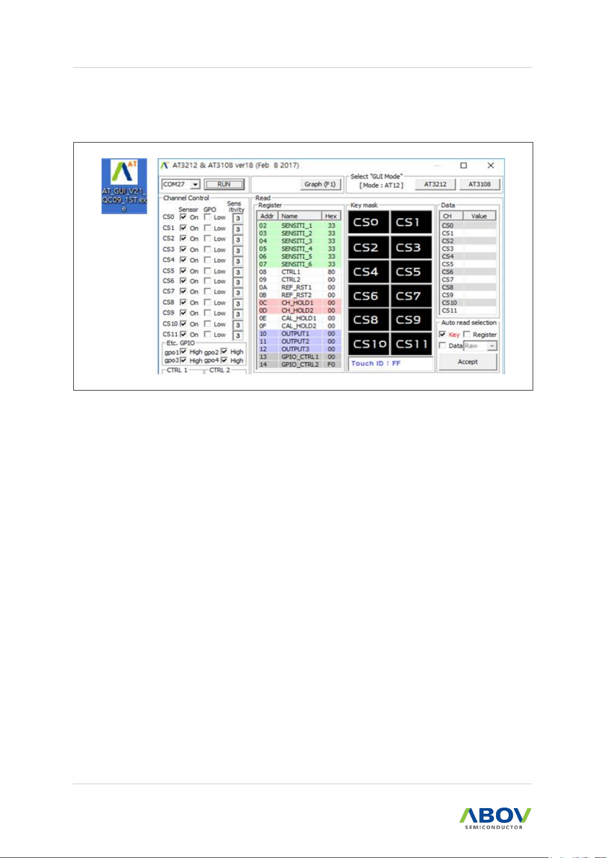
3.4 AT GUI program practice...................................................................................................14
3.4.1 Run the AT GUI program ......................................................................................14
3.4.2 Viewing values in AT GUI program .......................................................................15
3.4.3 Options of Auto Read Selection ...........................................................................16
3.4.4 View Graph (Plot) .................................................................................................18
3.4.5 Register value settings .........................................................................................19
3.5 Software description..........................................................................................................21
3.5.1 Flow chart for overall workflow .............................................................................21
3.5.2 Touch Mode Selection ..........................................................................................22
3.5.3 How to enter Sleep Mode .....................................................................................23
3.5.4 I2C Communication method during Sleep Mode .................................................24
3.5.5 Register value settings and digital output pin use ................................................25
3.5.6 Loop operation and register value update............................................................26
3.5.7 I2C master example code.....................................................................................27
Revision history .....................................................................................................................................31

AT3212U Demo board quick start guide List of figures/ List of tables
3
List of figures
Figure 1. I2C to UART Board Layout (Hardware) ...................................................................................5
Figure 2. AT3212U Touch Board Layout (Hardware) ..............................................................................5
Figure 3. AT GUI Program (Software) .....................................................................................................6
Figure 4. Window PC and Micro B Cable ...............................................................................................7
Figure 5. ABOV Semiconductor Website ................................................................................................7
Figure 6. I2C to UART Board Layout ......................................................................................................9
Figure 7. Touch Demo Board Description .............................................................................................10
Figure 8. I2C to UART Board Description .............................................................................................11
Figure 9. I2C to UART Board and Touch Demo Board Connection......................................................12
Figure 10. USB Cable and I2C to UART Board Connection.................................................................13
Figure 11. AT GUI Program Icon ...........................................................................................................14
Figure 12. AT GUI Program Menu.........................................................................................................14
Figure 13. Viewing Values in AT GUI Program .....................................................................................15
Figure 14. Run (Start Code Execution) .................................................................................................16
Figure 15. Data Menu Options ..............................................................................................................17
Figure 16. Graph of Channels...............................................................................................................18
Figure 17. Register Value Settings (Part1) ...........................................................................................19
Figure 18. Register Value Settings (Part2) ...........................................................................................20
Figure 19. Flow Chart of Register Setup Operations ............................................................................21
Figure 20. Timing Diagram of Touch Sensor Operation in Fast Mode (Active Mode) ..........................22
Figure 21. Timing Diagram of Touch Sensor Operation in Sleep Mode (Snap Mode)..........................22
Figure 22. Timing Diagram of Delay Time in Sleep Mode (Snap Mode) ..............................................23
Figure 23. Timing Diagram of Touch Event Occurrences in Sleep Mode .............................................24
Figure 24. Timing Diagram of I2C_EN occurrences in Sleep Mode .....................................................24
Figure 25. Flow Chart of Register Setup Loop Operations...................................................................26
Figure 26. AT3212.h ..............................................................................................................................27
Figure 27. AT3212.c ..............................................................................................................................29
List of tables
Table 1. Touch Demo Board Description...............................................................................................10
Table 2. Example Register Value Settings (Part2) ................................................................................20

1. Introduction AT3212U Demo board quick start guide
4
1Introduction
AT3212 Demo Board Quick Start Guide introduces software environment and development
recommendations for the ABOV Logic Type Touch Key.
In this document, we introduce an AT GUI program and a method to operate AT3212U Touch Demo
Board with examples. By reading this document thoroughly, you can learn the easy way to develop the
ABOV Logic Type Touch Key.

AT3212U Demo board quick start guide 2. User requirements
5
2User requirements
2.1 Hardware
2.1.1 I2C to UART Board
Figure 1. I2C to UART Board Layout (Hardware)
2.1.2 Touch Demo Board
Figure 2. AT3212U Touch Board Layout (Hardware)

2. User requirements AT3212U Demo board quick start guide
6
2.2 Software
You can debug using the AT GUI program.
Figure 3. AT GUI Program (Software)
2.3 Reference documents
AT3212U Quick Guide
AT3212U HW Manual
AT3212U Schematic
Product User’s Manual
Master Example Code

AT3212U Demo board quick start guide 2. User requirements
7
2.4 System requirements
Windows PC (7, 8, 10)
USB Micro B type cable
Figure 4. Window PC and Micro B Cable
2.5 ABOV website
For detailed information about the corresponding software and documents, you can visit our website at
https://www.abovsemi.com.
Figure 5. ABOV Semiconductor Website

3. Building and running project AT3212U Demo board quick start guide
8
3Building and running project
Running the AT GUI program makes it easier to start the Touch Demo Board. Follow the steps below
to start the Demo Board:
Step 1. Prepare the I2C to UART Board and Touch Demo Board.
Step 2. Set up the I2C to UART Board and Touch Demo Board.
Step 3. Connect the I2C to UART Board to your PC.
Step 4. Run the AT GUI program.

AT3212U Demo board quick start guide 3. Building and running project
9
3.1 Prepare the I2C to UART Board and Touch Demo Board
3.1.1 Hardware components of the I2C to UART Board
1. The I2C to UART Board operates as an I2C Master based on the Touch Demo Board, and
contacts your PC through UART communication.
2. The I2C to UART Board is connected to the USB port on your PC, and can be tested using
the GUI program.
Figure 6. I2C to UART Board Layout

3. Building and running project AT3212U Demo board quick start guide
10
3.1.2 Hardware components of the Shield Board
1. AT3212 (24-QFN) chip: Touch Sensing 12CH (channel) and LED 4 pins are supported.
2. The 2mm (2T) Thick plastic cover is attached to the Touch PAD.
Table 1. Touch Demo Board Description
Function
Description
Remark
Touch Key
User SW
Touch Only Pin (CS0~CS11)
GPIO
User SW
GPIO12, GPIO13, OUT1, OUT2
External Interface
User SW
VDD, GND, INT,SDA, SCL, I2C_EN, RESET, OUT_MODE
Figure 7. Touch Demo Board Description

AT3212U Demo board quick start guide 3. Building and running project
11
3.2 Set up the I2C to UART Board and Touch Demo Board
3.2.1 Set jumpers to control the I2C to UART Board
1. You can select a power source between USB power and external power using a jumper pin
(recommended to use +5V USB power). A 9-volt battery (a square battery) can be used as an
external power (max. 12V).
2. Again, you can use a jumper pin to select one between +5V and +3.3V of the selected power
source.
3. If the Option Jumper pin shown in Figure 8 is not connected (OFF), 12CH Logic Type Touch
Sensors are supported. (e.g., AT3212, ATS12)
4. If the Option Jumper pin shown in Figure 8 is connected (ON), 8CH Logic Type Touch Sensors
are supported. (e.g., AT3108)
Figure 8. I2C to UART Board Description

3. Building and running project AT3212U Demo board quick start guide
12
3.2.2 Connect to the I2C to UART Board to use the Touch Demo Board
Connect a header socket of the Touch Demo Board and the header pin of the I2C to UART Board as
shown in Figure 9.
Figure 9. I2C to UART Board and Touch Demo Board Connection

AT3212U Demo board quick start guide 3. Building and running project
13
3.3 Connect the I2C to UART Board to your PC
3.3.1 Connect PC via USB on the I2C to UART Board
1. Connect the USB 2.0 (micro-B type) cable to the I2C to UART Board as shown in Figure 10.
Figure 10. USB Cable and I2C to UART Board Connection

3. Building and running project AT3212U Demo board quick start guide
14
3.4 AT GUI program practice
3.4.1 Run the AT GUI program
1. Run the AT GUI program by double clicking over the icon shown in Figure 11.
Figure 11. AT GUI Program Icon
2. After the program starts, the COM port number is displayed on the screen as shown in Figure
12.
A. Click on the ‘RUN’button.
B. Click on the ‘AT3212’button, regardless of whether it is before or after the ‘RUN’button.
C. Click on the ‘Accept’button after marking the ‘Key’box.
Figure 12. AT GUI Program Menu

AT3212U Demo board quick start guide 3. Building and running project
15
3.4.2 Viewing values in AT GUI program
When a Touch Key on the Demo Board is touched by your finger, a corresponding LED on the
Communication Board (I2C to UART Board) lights up. At the same time, the GUI program displays the
corresponding key in red, as shown in Figure 13.
If the GUI program does not display the key in red, users can solve the problem by marking
the ‘Key' box in the ‘Auto read selection’ settings and pressing the ‘Accept’key.
The ‘Auto read selection’ settings allow to automatically read and display the values,
regardless of whether or not the Touch Event is generated.
Figure 13. Viewing Values in AT GUI Program

3. Building and running project AT3212U Demo board quick start guide
16
3.4.3 Options of Auto Read Selection
1. Key: It supports key display activation.
Figure 14. Run (Start Code Execution)

AT3212U Demo board quick start guide 3. Building and running project
17
2. Data: RAW, Baseline, Threshold, Percentage
A. RAW Data (Original touch sensitivity value)
B. Baseline Data (Baseline reference value)
C. Threshold (THD; Touch detection reference value)
D. Percentage (Current Sensitivity percentage based on the THD value of 100%)
Example)
The percentage value of 223% implies that the Current Sensitivity value is 2.23 times
higher than the THD value. That is, in a condition of THD = 80, the Current Sensitivity
value is 178 (80 X 2.23 = 178).
Figure 15. Data Menu Options

3. Building and running project AT3212U Demo board quick start guide
18
3.4.4 View Graph (Plot)
1. Press the ‘Graph’ button at the top of the GUI program or press ‘F1’ function key. You can see
the values of all channels on the screen, as shown in Figure 16.
2. To activate, make sure to select a Data type in the ‘Auto read selection’ settings.
—Data: RAW, Baseline, Threshold, Percentage
⬧RAW Data (Original touch sensitivity value)
⬧Baseline Data (Baseline reference value)
⬧Threshold (THD; Touch detection reference value)
⬧Percentage (Current Sensitivity percentage based on the THD value of 100%)
Figure 16. Graph of Channels

AT3212U Demo board quick start guide 3. Building and running project
19
3.4.5 Register value settings
For the register value settings, we provide two methods: Part 1 and Part 2. Using the Part 1, you can
mark check boxes or write values to set the registers. Using the Part 2, you can write I2C commands
directly to set the registers.
1. Part 1:
A. Click on the ‘Refresh’ button to read the register values currently set in the Touch Sensor
chip. This will update the registers.
B. When you finish changing the settings, press the ‘Write’ button to complete the change.
You can see the changes in the ‘Register window’ as shown in Figure 17.
Figure 17. Register Value Settings (Part1)

3. Building and running project AT3212U Demo board quick start guide
20
2. Part 2:
A. Write register address and setting value in the Part 2-input window, as shown in Figure
18. Then, press the ‘Write’ button.
B. Or you can enter Multi-byte data that has the address as a starting address. Then, press
the ‘Write’ button.
Figure 18. Register Value Settings (Part2)
C. Example settings)
⬧In Single Key Result Mode, for the simultaneous keys, the result is always 1 Key
(initial value).
⬧In Single Key Noise Mode, for the simultaneous keys, the result is Not Touch.
⬧In Multi Key Mode, for the simultaneous keys, the result is Simultaneous Key.
Table 2. Example Register Value Settings (Part2)
Function
Description
Remark
SENSITIVITY1 Update
02 22
Start F0 02 22 Stop
SENSITIVITY1~6 Update
02 44 44 44 44 44 44
Start F0 02 44 44 44 44 44 44 Stop
Single Key Result Mode
1F 09
Start F0 1F 09 Stop
Single Key Noise Mode
1F 19
Start F0 1F 19 Stop
Multi Key Mode
1F 0D
Start F0 1F 0D Stop
Sleep Mode (Snap Mode)
08 00 04
Start F0 08 00 04 Stop
Fast Mode (Active Mode)
08 80 00
Start F0 08 80 00 Stop
GPIO_CTRL2 Update
14 F0
Start F0 14 F0 Stop
Table of contents
Other Abov Motherboard manuals