Abov E-PGM+ User manual

Contents E-PGM+ / E-GANG4/6 / E-PGM Serial User’s Manual
2
Contents
1Introduction ....................................................................................................................................6
2Hardware........................................................................................................................................7
2.1 Specifications ......................................................................................................................7
2.2 Functions.............................................................................................................................8
2.2.1 E-PGM+ Programmer.............................................................................................8
2.2.2 E-PGM Serial Programmer...................................................................................10
2.2.3 E-GANG4/E-GANG6 Programmer .......................................................................12
2.3 Pin Configuration...............................................................................................................15
2.3.1 40-pin DIP TEXTOOL Socket ...............................................................................15
2.3.2 10-pin Connector ..................................................................................................16
3Software .......................................................................................................................................17
3.1 Software Release ..............................................................................................................17
3.2 Software Installation ..........................................................................................................18
3.3 Software UI Descriptions...................................................................................................22
3.4 Device Selection................................................................................................................33
3.5 Programmer Self Check....................................................................................................35
3.6 Programming Error Messages ..........................................................................................37
3.7 Troubleshooting.................................................................................................................38
3.7.1 Error Message: ‘The program can’t start because WDAPI1010.dll is missing.‘ ...38
3.7.2 Error Message: ‘No firmware found’ or ‘Device file not found!‘ ............................38
3.7.3 Error Message: ‘No valid license‘ or ‘Received an invalid 32-bit LOCTL’ ............39
4Connection of Handler .................................................................................................................40
4.1 E-PGM+ / E-PGM Serial Handler Connections.................................................................40
4.2 E-GANG4 Handler Connections .......................................................................................41
4.3E-GANG6 Handler Connections .......................................................................................42
5Connecting Multiple E-PGM+ Units .............................................................................................43
6PCB V5.5 SW3 Settings...............................................................................................................44
Revision History ....................................................................................................................................46

E-PGM+ / E-GANG4/6 / E-PGM Serial User’s Manual List of Figures
3
List of Figures
Figure 1. Programmer .............................................................................................................................6
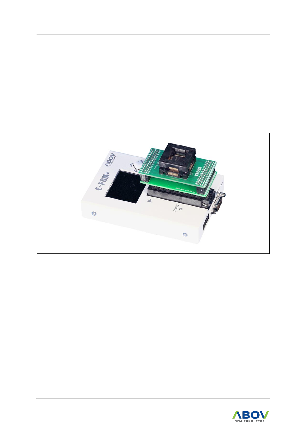
Figure 2. E-PGM+ with Target Socket Module........................................................................................8
Figure 3. E-PGM+ Top and Side Views for Function Description ...........................................................9
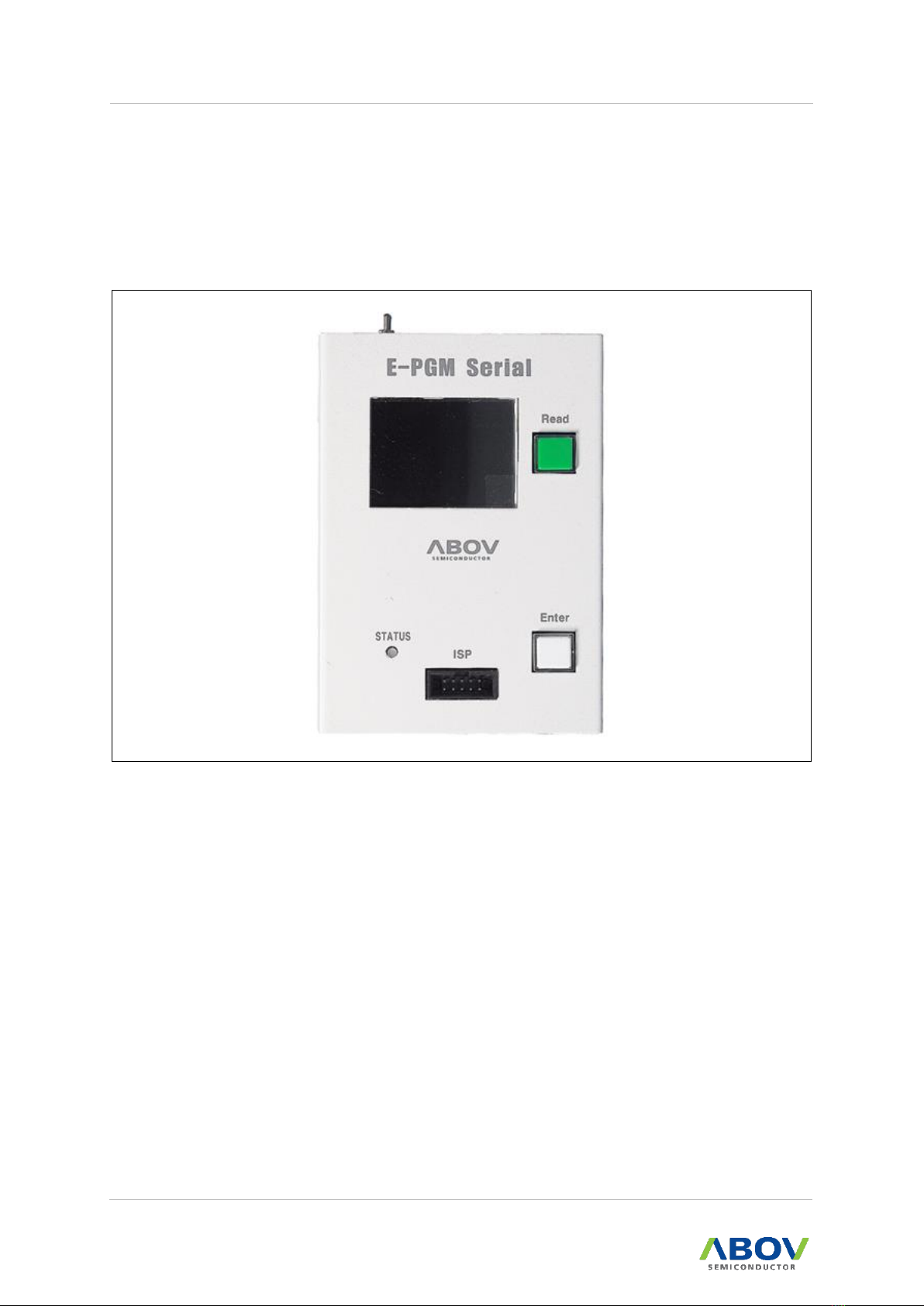
Figure 4. E-PGM Serial Programmer ....................................................................................................10
Figure 5. E-PGM Serial Top and Side Views for Function Description .................................................11
Figure 6. E-GANG4 Programmer..........................................................................................................12
Figure 7. E-GANG6 Programmer..........................................................................................................12
Figure 8. E-GANG6 Top and Side Views for Function Description .......................................................13
Figure 9. Programming Pin Assignment for 40-pin DIP TEXTOOL ......................................................15
Figure 10. Programming Pin Assignment for 10-pin Connector ...........................................................16
Figure 11. Software Download ..............................................................................................................18
Figure 12. USB_driver_install.exe ........................................................................................................18
Figure 13. Windows security .................................................................................................................19
Figure 14. Driver Installation .................................................................................................................19
Figure 15. Device Manager...................................................................................................................20
Figure 16. E-PGM+.exe ........................................................................................................................20
Figure 17. Windows’ Warning Message................................................................................................21
Figure 18. Unblock under Security in Properties Menu ........................................................................21
Figure 19. E-PGM+ PC Program ..........................................................................................................22
Figure 20. Software Version Information...............................................................................................22
Figure 21. Select Hex File Type ............................................................................................................23
Figure 22. Save HPO ............................................................................................................................23
Figure 23. Displayed Progress Bar .......................................................................................................24
Figure 24. Example: Options of A96T418 .............................................................................................24
Figure 25. Device Password .................................................................................................................25
Figure 26. Device Select .......................................................................................................................26
Figure 27. Displayed Progress Bar .......................................................................................................26
Figure 28. Choose Type........................................................................................................................27
Figure 29. Save HOP (OFF LINE)/Get Code Checksum......................................................................27
Figure 30. Set VDD ...............................................................................................................................28
Figure 31. Tool Options: Erase Data Flash ...........................................................................................29
Figure 32. Tool Options: Config. Serial ID.............................................................................................29
Figure 33. Options of Config. Serial ID .................................................................................................30
Figure 34. Tool Options: Config. Limit Number of Write........................................................................31
Figure 35. Write Counter.......................................................................................................................31
Figure 36. Log Dialog............................................................................................................................32
Figure 37. Port Selection.......................................................................................................................33
Figure 38. Device Selection, Load Hex, and Update ............................................................................33
Figure 39. E-PGM+ Software Settings for Self Check ..........................................................................35
Figure 40. Button of Programmers........................................................................................................36
Figure 41. Self Check Results...............................................................................................................36
Figure 42. Error Message of WDAPI1010.DLL.....................................................................................38
Figure 43. Error Message of Firmware or Device File ..........................................................................38
Figure 44. Error Message of Validity .....................................................................................................39
Figure 45. windrvr6.ssys .......................................................................................................................39
Figure 46. E-PGM+ Handler Connections ............................................................................................40
Figure 47. E-GANG4 Handler Connections ..........................................................................................41
Figure 48. E-GANG6 Handler Connections ..........................................................................................42

List of Figures E-PGM+ / E-GANG4/6 / E-PGM Serial User’s Manual
4
Figure 49. Example of Multiple Connections of E-PGM+ .....................................................................43
Figure 50. Internal Step-up Power Selection ........................................................................................44
Figure 51. Insertion of 200 Ohms in VPP Line......................................................................................45

E-PGM+ / E-GANG4/6 / E-PGM Serial User’s Manual List of Tables
5
List of Tables
Table 1. Programmer Specifications .......................................................................................................7
Table 2. Programmer Functions..............................................................................................................7
Table 3. Pin Assignment for 40-pin TEXTOOL Socket..........................................................................15
Table 4. Connection Table for 10-pin IDC Connector............................................................................16
Table 5. Error Messages and Causes ...................................................................................................37

1. Introduction E-PGM+ / E-GANG4/6 / E-PGM Serial User’s Manual
6
1Introduction
E-PGM+, E-GANG4/6 and E-PGM Serial series are the universal programming equipment for the
ABOV Semiconductor’s MCU series, delivering superior performance and reliability.
This product line-up has the following features:
Fast programming speed for mass manufacturing
Standalone programming and automated programming
Supports USB (2.0 Full-Speed) interface with Microsoft Windows.
Built-in protection circuit for the Programmer and programmed device
Data port inputs are protected against ESD up to 15kV.
Supports single chip programmer mode using socket for a device (Except for E-PGM
Serial).
Supports Gang programmer mode using four or six socket devices.
Supports On-board Programmer using In-System Programming (ISP) mode.
Up to 1Mbit internal Flash memory for target binary or hex format data
Programming supports the main code area and the option area as well.
(a) E-PGM+
(b) E-PGM Serial
(c) E-GANG4
(d) E-GANG6
Figure 1. Programmer

E-PGM+ / E-GANG4/6 / E-PGM Serial User’s Manual 2. Hardware
7
2Hardware
2.1 Specifications
The E-PGM+ and E-GANG4/GANG6 have similar features, but the E-PGM Serial has different
features. The E-PGM Serial was designed only for On-board Programming purpose and features
Noise Robust for the mass production environment.
Specifications of each Programmer equipment are compared in Table 1.
Table 1. Programmer Specifications
E-PGM+
E-PGM Serial
E-GANG4
E-GANG6
Type
Standalone Type Universal Programmer
Dimension [Cm]
8.3 X 14.5 X 3.3
8.3 X 14.5 X 3.3
33.5 X 23 X 4.3
48.2 X 23 X 4.3
Weight [g]
350
330
2,000
2,800
Power Source
External DC 15V Power Supply
Input Voltage
15V/1A
15V/1A
15V/2A
15V/2A
Power Consumption
15W
15W
30W
30W
Operating Temp.
-10℃~ 40℃
Storage Temp.
-30℃~ 80℃
Functions of each Programmer equipment are compared in Table 2.
Table 2. Programmer Functions
E-PGM+
E-PGM Serial
E-GANG4/6
40-DIP Socket
O
X
O
ISP Port
O
O
O
ISP Port ESD/
EOS/
Surge Protection
O
Level shifter added
VDD Protection Diode added
O
Supported Devices
All Devices
94/95/96/97XXXX series
(except for 97F1104S/1204S/1316S)
All 32-bit MCU
All Devices
Buffer Size
1MB
8MB
1MB
Read Button
Joystick Button
Push Button
Joystick Button
Support Barcode
Reader (RS-232C)
O
X
X
Handler Interface
O
O
O
Operating S/W
E-PGM+.exe
E-PGM+.exe
E-PGM+.exe

2. Hardware E-PGM+ / E-GANG4/6 / E-PGM Serial User’s Manual
8
2.2 Functions
The E-PGM+, E-GANG4/6 and E-PGM Serial are designed as a compact system for every
workspace. They are easy to use with simple and convenient features.
Consumable parts such as a 40-pin DIP socket, ENTER button, and joystick buttons are
individually replaceable, ensuring a long service life. Functions of the E-PGM+, E-GANG4/6 and
E-PGM Serial are described in the following sections:
2.2.1 E-PGM+ Programmer
The E-PGM+ is a standalone type universal Programmer, which is capable of programming any
series of ABOV’s microcontrollers. The E-PGM+ consists of main Programmer equipment and the
target device socket and socket adaptor parts.
Figure 2. E-PGM+ with Target Socket Module

E-PGM+ / E-GANG4/6 / E-PGM Serial User’s Manual 2. Hardware
9
Figure 3 and the following list describe external features of the E-PGM+:
Figure 3. E-PGM+ Top and Side Views for Function Description
①10-pin IDC connector for In-System Programming (ISP)
②RS-232C serial communication port (External bar code reader interface port)
③SWD port for firmware update and development purpose (Do not use, it is not for
customers.)
④A button for programming the target device
⑤A button for reading the target device
⑥LCD Screen for Information Display:
—Device name, checksum data and options.
—PASS/FAIL is shown as a result of programming, accompanied by error information
in the case of failure.
⑦40-pin DIP TEXTOOL Socket for single chip programming mode.
⑧LED Indicator with red/green illumination shows the current status when writing is
complete:
—Red for FAIL
—Green for PASS
⑨5-pin Molex 5264 connector for the interface with a Handler equipment
⑩USB mini-B connector to a PC
⑪Power Adaptor Connector for the 15V/1A external power
⑫System Power Switch

2. Hardware E-PGM+ / E-GANG4/6 / E-PGM Serial User’s Manual
10
2.2.2 E-PGM Serial Programmer
The E-PGM Serial is the standalone ISP type universal Programmer, which is capable of
programming any series of ABOV’s Flash microcontrollers: 94/95/96/97XXXX series (except for
97F1104S/1204S/1316S) and all 32 bit MCUs.
The E-PGM Serial is used for On-board manufacturing purpose because the E-PGM Serial does
not have TEXTOOL Socket.
Figure 4. E-PGM Serial Programmer

E-PGM+ / E-GANG4/6 / E-PGM Serial User’s Manual 2. Hardware
11
Figure 5 and the following list describe external features of the E-PGM Serial.
Figure 5. E-PGM Serial Top and Side Views for Function Description
①10-pin IDC connector for In-System Programming (ISP)
②SWD port for firmware update and development purpose (Do not use, it is not for
customers.)
③A button for programming the target device
④A button for reading the target device
⑤LCD Screen for Information Display:
—Device name, checksum data and options.
—PASS/FAIL is shown as a result of programming, accompanied by error information
in the case of failure.
⑥LED Indicator with red/green illumination shows the current status when writing is
complete:
—Red for FAIL
—Green for PASS
⑦5-pin Molex 5264 connector for the interface with a Handler equipment
⑧USB mini-B connector to a PC
⑨Power Adaptor Connector for the 15V/1A external power
⑩System Power Switch

2. Hardware E-PGM+ / E-GANG4/6 / E-PGM Serial User’s Manual
12
2.2.3 E-GANG4/E-GANG6 Programmer
The E-GANG4 and E-GANG6 are standalone type universal gang Programmers, which are
capable of programming any series of ABOV’s microcontrollers with a gang mode that allows
multiple devices to be programmed simultaneously.
The E-GANG4 and E-GANG6 consist of four or six E-PGM+s, respectively. In addition, it includes
a power control board and USB-HUB.
Figure 6. E-GANG4 Programmer
Figure 7. E-GANG6 Programmer

E-PGM+ / E-GANG4/6 / E-PGM Serial User’s Manual 2. Hardware
13
Figure 8 and the following list describe external features of the E-PGM+.
Figure 8. E-GANG6 Top and Side Views for Function Description
①10-pin IDC connector for In-System Programming (ISP)
②SWD port for firmware update and development purpose (Not for use)
③A button for programming the target device ‘G1’ (only)
④A button for reading the target device
⑤LCD Screen for Information Display:
—Device name, checksum data and options
—PASS/FAIL is shown as a result of programming,
accompanied by error information in the case of failure.
⑥40-pin DIP TEXTOOL Socket for gang programming mode:
—Gang4 has four separate sockets.
—Gang6 has six separate sockets.

2. Hardware E-PGM+ / E-GANG4/6 / E-PGM Serial User’s Manual
14
⑦LED Indicator with red/green illumination shows the current status when writing is
complete.
—Red for FAIL
—Green for PASS
⑧A button for the simultaneous programming for all the four or six gangs
⑨System Power Switch of E-GANG4/6
⑩This connector is for the 15V/2A power adapter used to power E-GANG4/6.
⑪12-pin Molex 5264 connector for the interface with a Handler equipment
⑫USB mini-B connector to a PC

E-PGM+ / E-GANG4/6 / E-PGM Serial User’s Manual 2. Hardware
15
2.3 Pin Configuration
2.3.1 40-pin DIP TEXTOOL Socket
The E-PGM+ and E-GANG4/6 (except for E-PGM Serial) use specific sockets to program a device
or a gang of devices. Users should place the appropriate socket and adapter on the 40-pin DIP
TEXTOOL socket of the E-PGM+ or E-GANG4/6 before conducting programming. We provide all
sockets and adaptors which are supported by the E-PGM+ and E-GANG4/6. Please refer to the
Socket and Adaptor Selection Guide for the device to be programmed.
Figure 9 and Table 3 show signal assignments of the 40-pin DIP TEXTOOL Socket.
Figure 9. Programming Pin Assignment for 40-pin DIP TEXTOOL
Table 3. Pin Assignment for 40-pin TEXTOOL Socket
Pin No.
Pin Name
4
DATA
5
VDD
6
CLK (Clock)
7
Rung Flag/Boot
35
VPP/Reset
36
GND

2. Hardware E-PGM+ / E-GANG4/6 / E-PGM Serial User’s Manual
16
2.3.2 10-pin Connector
A 10-pin IDC type connector is required for On-board programming with E-PGM+, E-GANG4/6
and E-PGM Serial. The target board and 10-pin connector must be connected correctly for
programming. If the connection is incorrect, the “Device–ID Fail.” message is displayed on the
LCD screen.
Figure 10. Programming Pin Assignment for 10-pin Connector
Table 4. Connection Table for 10-pin IDC Connector
Pin No.
Supported Signals
AC33M6128/8128,
AC33M3064/4064
MC80F7708
UART ISP
32-bit SWD
1
MCU UART-RX
MCU UART-RX
MCU UART-RX
N/A
2
VDD
VDD
VDD
VDD
3
MCU UART-TX
MCU UART-TX
MCU UART-TX
N/A
4
GND
GND
GND
GND
5
Run Flag or Boot
Pin or ACK
Boot Pin
ACK
N/A
6
DSCL, CLK (Clock)
N/A
N/A
SWD-CLK
7
GND
N/A
N/A
N/A
8
DSDA, Data
N/A
N/A
SWD-DATA
9
N/A
N/A
N/A
N/A
10
VPP or Reset Pin
RESET
VPP
RESET

E-PGM+ / E-GANG4/6 / E-PGM Serial User’s Manual 3. Software
17
3Software
3.1 Software Release
Software and firmware of the E-PGM+, E-GANG4/6 and E-PGM Serial can be downloaded from
the ABOV Semiconductor’s website. The firmware for individual devices has been developed and
fully tested by us, and the certified version of program is uploaded to our website.
Additional software updates are provided through the special version development process upon
requests by customers. For more information about the special version development, please
contact our sales office.
The E-PGM+, E-GANG4/GANG6 and E-PGM Serial share a software program. When an
equipment is connected, the software program identifies the equipment and enumerates how
much equipment can be updated.

3. Software E-PGM+ / E-GANG4/6 / E-PGM Serial User’s Manual
18
3.2 Software Installation
To install the software, follow the steps below:
1. At the ABOV Semiconductor’s website www.abovsemi.com, go to the “Development
Tools > Programmer > E-PGM+ / E-Gang4/6 / E-PGM Serial” menu.
2. Download the E-PGM+ / E-GANG4/6 USB Driver for 32/64 bit OS and the E- PGM+ / E-
Gang Software shown in Figure 11.
Figure 11. Software Download
3. Proceed without connecting the E-PGM+ to a PC.
4. Unzip the ‘Epgm_driver_install_Ver_x.x.zip’, and open the created folder.
5. Run the ‘USB_driver_install.exe’.
Figure 12. USB_driver_install.exe

E-PGM+ / E-GANG4/6 / E-PGM Serial User’s Manual 3. Software
19
6. Click the ‘Install’button if the dialog box pops up as shown in Figure 13:
Figure 13. Windows security
7. After executing the ‘exe‘ file, the window shown in Figure 14 appears if the installation is
successful. The installation takes one to three minutes depending on the PC environment.
Figure 14. Driver Installation
The driver installation is complete when the “completed successfully” appears at the
bottom of the CMD window as shown in a blue circle in the figure above.

3. Software E-PGM+ / E-GANG4/6 / E-PGM Serial User’s Manual
20
8. Connect the E-PGM+ or E-GANG4/6 to the PC, and turn it on. The E-PGM+ or E-
GANG4/6 should be automatically recognized and displayed in Device Manager as shown
in Figure 15.
Figure 15. Device Manager
9. Unzip the E-PGM+ / E-GANG4/6 / E-PGM Serial Software that was downloaded in Step
2. In the created folder, double-click the executable (E-PGM+.exe) to run the program.
Figure 16. E-PGM+.exe
Other manuals for E-PGM+
1
This manual suits for next models
3
Table of contents
Other Abov Motherboard manuals