Abov E-PGM+ User manual

Leader of Microcontroller Technology
Global Top Smart MCU Innovation Company
Leader of Microcontroller Technology
Global Top Smart MCU Innovation Company
Leader of Microcontroller Technology
Global Top Smart MCU Innovation Company
E-PGM+
E-GANG4/E-GANG6
E-PGM Serial
User Manual
Version 1.0.0
Jun. 28, 2019
For additional information or inquiry, please contact ABOV Semiconductor
or visit its website at www.abov.co.kr.

Revision History
Date Version Description
Jun. 28, 2019 1.0.0 Document created.
Date Version Description
Jun. 28, 2019 1.0.0 Document created.
E-PGM+ E-GANG4/E-GANG6 E-PGM Serial Page 2 / 33 Version 1.0.0

Contents
Chapter 1. Introduction . . . . . . . . . . . . . . . . . . . . . . . . . . . . . . . . . . . . . . 5
Chapter 2. Hardware . . . . . . . . . . . . . . . . . . . . . . . . . . . . . . . . . . . . . . . . 6
2.1. Specifications . . . . . . . . . . . . . . . . . . . . . . . . . . . . . . . . . . . 6
2.2. Functional comparison . . . . . . . . . . . . . . . . . . . . . . . . . . . . . . 6
2.3. Functions . . . . . . . . . . . . . . . . . . . . . . . . . . . . . . . . . . . . . 7
2.3.1. E-PGM+ . . . . . . . . . . . . . . . . . . . . . . . . . . . . . . . . . . . 7
2.3.2. E-GANG4/E-GANG6 . . . . . . . . . . . . . . . . . . . . . . . . . . . . . 9
2.3.3. E-PGM Serial . . . . . . . . . . . . . . . . . . . . . . . . . . . . . . . . . 11
2.4. 40-pin DIP TEXTOOL socket pin configuration . . . . . . . . . . . . . . . . . . 12
2.5. 10-pin connector pin configuration . . . . . . . . . . . . . . . . . . . . . . . . 13
Chapter 3. Software . . . . . . . . . . . . . . . . . . . . . . . . . . . . . . . . . . . . . . . . 15
3.1. Software releases . . . . . . . . . . . . . . . . . . . . . . . . . . . . . . . . 15
3.2. Software installation . . . . . . . . . . . . . . . . . . . . . . . . . . . . . . . 15
3.3. Software UI descriptions . . . . . . . . . . . . . . . . . . . . . . . . . . . . . 19
3.4. Device selection . . . . . . . . . . . . . . . . . . . . . . . . . . . . . . . . . 23
3.5. Programming error messages . . . . . . . . . . . . . . . . . . . . . . . . . . 25
3.6. Troubleshooting . . . . . . . . . . . . . . . . . . . . . . . . . . . . . . . . . 25
3.6.1. Error message: “The program can’t start because WDAPI1010.dll is
missing from your computer. Try reinstalling the program to fix this problem.” . . . . 25
3.6.2. Error message: “No firmware found” or “Device file not found!” . . . . . . . 26
3.6.3. Error message: “No valid license” or “Received an invalid 32bit LOCTL” . . 26
Chapter 4. Connection to handler. . . . . . . . . . . . . . . . . . . . . . . . . . . . . . . . . 28
4.1. E-PGM+ handler connections . . . . . . . . . . . . . . . . . . . . . . . . . . 28
4.2. E-GANG4 handler connections . . . . . . . . . . . . . . . . . . . . . . . . . . 29
4.3. E-GANG6 handler connections . . . . . . . . . . . . . . . . . . . . . . . . . . 30
Chapter 5. Connecting multiple E-PGM+ units. . . . . . . . . . . . . . . . . . . . . . . . . . 31
Chapter 6. For MC97F1104S/1204S/1316S only . . . . . . . . . . . . . . . . . . . . . . . . . 32
List of Figures
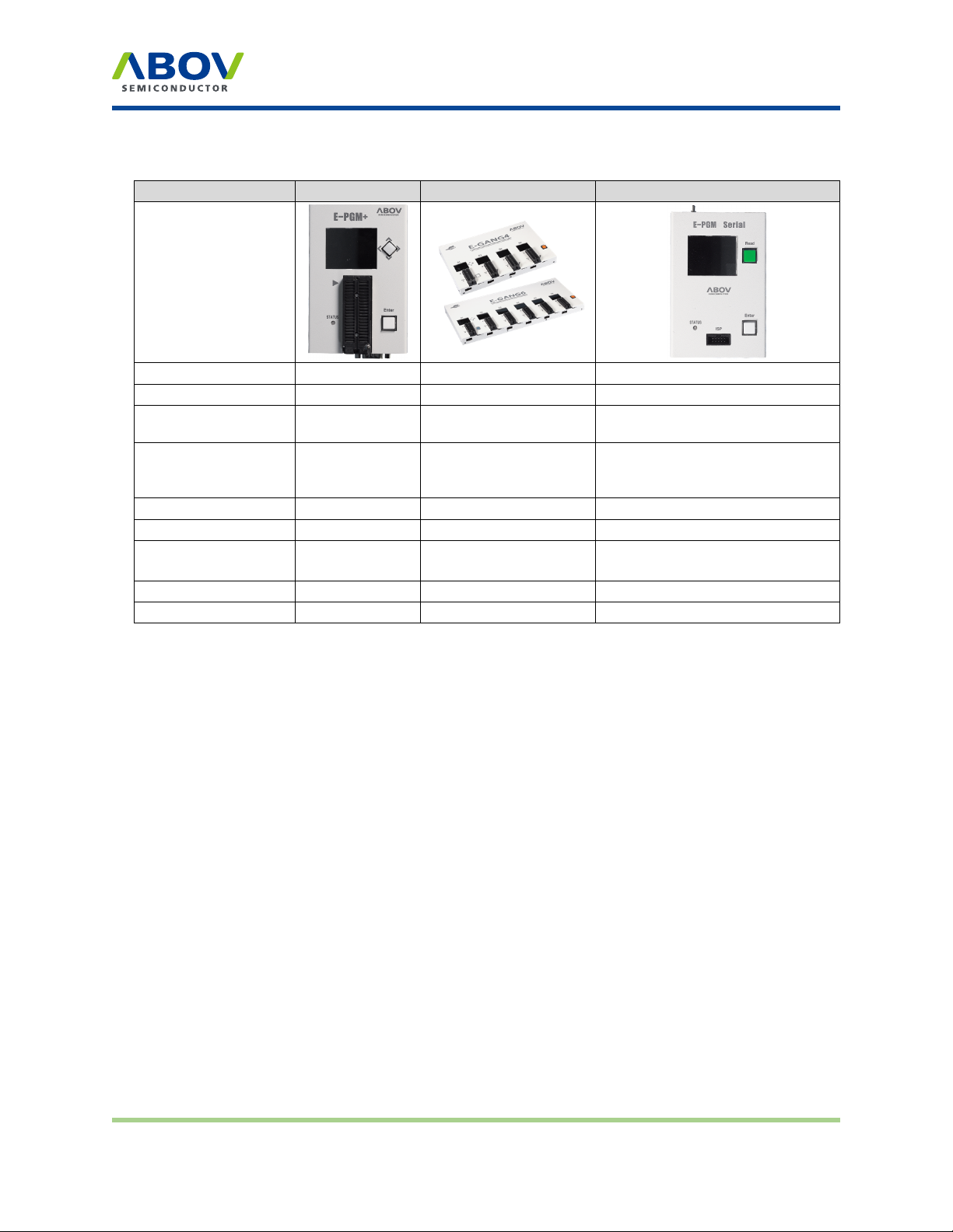
Figure 1 E-PGM+ with target socket module . . . . . . . . . . . . . . . . . . . . . . . . . . . 8
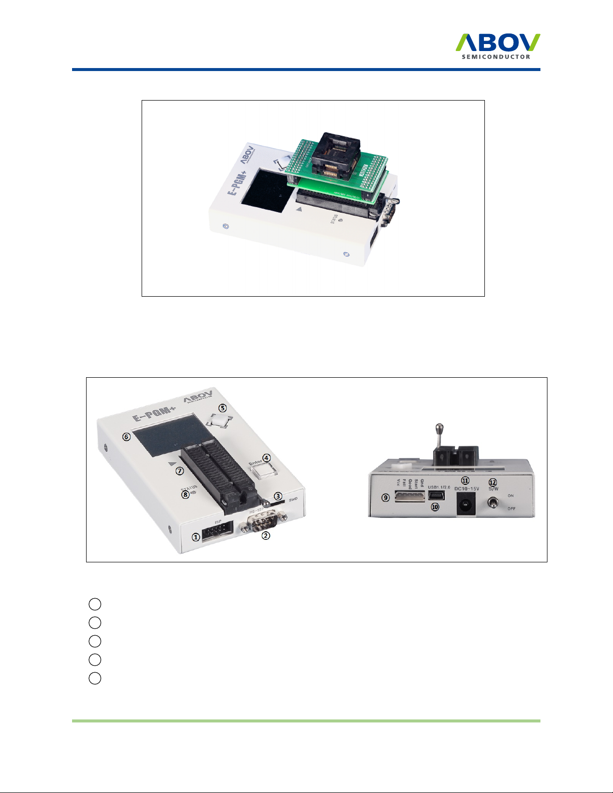
Figure 2 E-PGM+ top and side views for function description . . . . . . . . . . . . . . . . . 8
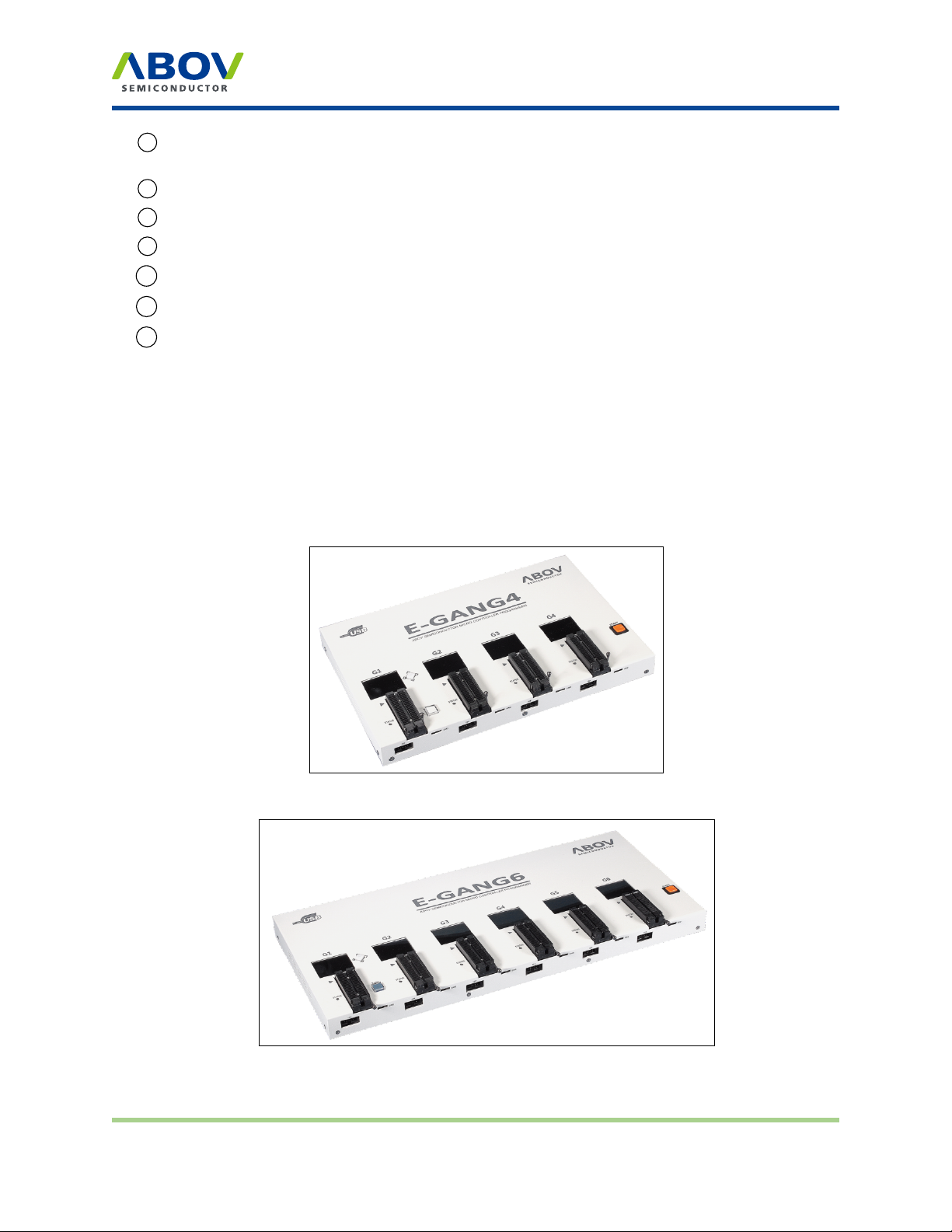
Figure3 E-GANG4exteriorview ................................. 9
Figure4 E-GANG6exteriorview ................................. 9
Figure 5 E-GANG6 exterior view for function description . . . . . . . . . . . . . . . . . . . . 10
Version 1.0.0 Page 3 / 33 E-PGM+ E-GANG4/E-GANG6 E-PGM Serial

Figure 6 E-PGM serial exterior view . . . . . . . . . . . . . . . . . . . . . . . . . . . . . . . 11
Figure 7 E-PGM Serial top and side views for function description . . . . . . . . . . . . . . . 12
Figure 8 40-pin DIP TEXTOOL socket and programming pin assignment . . . . . . . . . . . 13
Figure 9 10-pin IDC connector pin assignment . . . . . . . . . . . . . . . . . . . . . . . . . 14
Figure 10 An example connection of multiple E-PGM+ units . . . . . . . . . . . . . . . . . . . 31
Figure 11 Internal step-up power selection . . . . . . . . . . . . . . . . . . . . . . . . . . . . 32
Figure 12 Insertion of a 200 ohm resistor in VPP line . . . . . . . . . . . . . . . . . . . . . . . 33
List of Tables
Table 1 Comparison between E-PGM+, E-GANG4/6, and E-PGM Serial . . . . . . . . . . . 7
Table 2 Pin name and assignment . . . . . . . . . . . . . . . . . . . . . . . . . . . . . . . . 13
Table 3 10-pin IDC connector pin configuration for each device group . . . . . . . . . . . . 14
E-PGM+ E-GANG4/E-GANG6 E-PGM Serial Page 4 / 33 Version 1.0.0

Introduction
Chapter 1. Introducon
E-PGM+, E-GANG4/6 and E-PGM Serial series are universal programming equipment for the ABOV
Semiconductor’s MCU series, delivering superior performance and reliability. This products line has the
following features:
• Deliver high programming speed for mass manufacturing
• Standalone programming and automated programming
• Support USB (2.0 full-speed) interface with Microsoft Windows
• Built-in protection circuit for the programmer and target device
• Data port inputs are protected against ESD up to 15 kV
• Support single chip programming mode via the device socket (except for E-PGM Serial)
• Support Gang programming mode via four or six device sockets
• Support in-system programming (ISP) as an on-board programmer
• Capacity of internal flash memory for target binary or hexa format data:
–E-PGM+/E-GANG4/6: 1 Mbytes
–E-PGM Serial: 8 Mbytes
• Support programming of both the main code and option areas
Version 1.0.0 Page 5 / 33 E-PGM+ E-GANG4/E-GANG6 E-PGM Serial

Hardware
Chapter 2. Hardware
2.1 Specicaons
• Product name: E-PGM+, E-GANG4/6, E-PGM Serial
• Standalone type universal programmer
• External 15 VDC Power supply
• Dimensions (W x D x H)
–E-PGM+: 8.3 cm x 14.5 cm x 3.3 cm
–E-GANG4: 33.5 cm x 22.5 cm x 3.5 cm
–E-GANG6: 48.2 cm x 22.5 cm x 3.5 cm
–E-PGM Serial: 8.3 cm x 13.3 cm x 3.3 cm
• Weight
–E-PGM+: 0.35 kg
–E-GANG: 2.0 kg
–E-GANG: 2.8 kg
–E-PGM Serial: 0.33 kg
• Input voltage
–E-PGM+: DC adaptor 15V/1A
–E-GANG4/6: DC adaptor 15V/2A
–E-PGM Serial: DC adaptor 15V/1A
• Power consumption: 15W, 30W (E-GANG4, E-GANG6)
• Operating temperature: -10°C to 40°C
• Storage temperature: -30°C to 80°C
2.2 Funconal comparison
E-PGM+ and E-GANG4/GANG6 have similar features, while E-PGM Serial is different from them as it
is designed only for on-board programming purposes and to be noise-robust for use in mass production
environments.
E-PGM+ E-GANG4/E-GANG6 E-PGM Serial Page 6 / 33 Version 1.0.0

Functions
Table 1: Comparison between E-PGM+, E-GANG4/6, and E-PGM Serial
E-PGM+ E-GANG4/6 E-PGM Serial
40-pin DIP socket ○ ○ ×
ISP port ○ ○ ○
ISP port surge
reinforcement ○ ○ ◎
Supported devices All devices All devices
94/95/96/97XXXX series (except
for 97F1104S/1204S/1316S)
All 32-bit MCUs
Buffer size 1MB 1MB 8MB
Read button Joystick button Joystick button Push button
Support barcode
reader (RS-232C) ○× ×
Handler interface ○ ○ ○
Operating software E-PGM+.exe E-PGM+.exe E-PGM+.exe
2.3 Funcons
E-PGM+, E-GANG4/6 and E-PGM Serial are designed as a compact system suitable for every
workspace, and are easy to use with simple and convenient features. Consumable parts such as the
40-pin DIP socket, Enter button, and joystick buttons are individually replaceable, ensuring a long service
life. The functions of E-PGM+, E-GANG4/6 and E-PGM Serial are described below:
2.3.1 E‐PGM+
E-PGM+ is a standalone-type universal programmer capable of programming ABOV’s all microcontroller
series. It consist of a main programmer unit and target device socket, and socket adaptor parts.
Version 1.0.0 Page 7 / 33 E-PGM+ E-GANG4/E-GANG6 E-PGM Serial

Functions
Figure 1: E-PGM+ with target socket module
Exterior features of E‐PGM+
Figure 2: E-PGM+ top and side views for function description
1 10-pin IDC connector for in-system programming (ISP)
2 RS-232C serial communication port (external bar code reader interface port)
3SWD port for firmware update and development purposes (not for use)
4Button for programming the target device
5 Button for reading the target device
E-PGM+ E-GANG4/E-GANG6 E-PGM Serial Page 8 / 33 Version 1.0.0

Functions
6 LCD screen for information display—device name, checksum data, and options. PASS/FAIL is
shown as a result of programming, accompanied by an error description in case of failure
7 40-pin DIP TEXTOOL socket for single chip programming mode
8 LED indicator showing the current status when writing is complete (Red: FAIL / Green: PASS)
9 5-pin Molex 5264 connector for the interface with handler equipment
10 USB mini-B connector to a PC
11 Power adaptor connector for the 15V/1A external power
12 System power switch
2.3.2 E‐GANG4/E‐GANG6
E-GANG4 and E-GANG6 are standalone-type universal gang programmers capable of programming
ABOV’s all microcontroller series in gang mode, which enables programming multiple devices at once.
E-GANG4 and E-GANG6 consist of a main programmer unit, target device socket, and socket adaptor
parts. When in on-board programming mode, they can be used in connection with an external handler
or manufacturing equipment without using the socket and the socket adaptor.
Figure 3: E-GANG4 exterior view
Figure 4: E-GANG6 exterior view
Version 1.0.0 Page 9 / 33 E-PGM+ E-GANG4/E-GANG6 E-PGM Serial

Functions
Exterior features of E‐GANG6
Figure 5: E-GANG6 exterior view for function description
1 10-pin IDC connector for in-system programming (ISP)
2SWD port for firmware update and development purposes (not for use)
3 Button for programming the target device “G1” only
4 Button for reading the target device
5 LCD screen for information display—device name, checksum data, and options. PASS/FAIL is
shown as a result of programming, accompanied by an error description in case of failure
640-pin DIP TEXTOOL socket for gang programming mode—Gang4 has four separate sockets
and Gang6 has six separate sockets
7 LED indicator showing the current status when writing is complete (Red: FAIL / Green: PASS)
E-PGM+ E-GANG4/E-GANG6 E-PGM Serial Page 10 / 33 Version 1.0.0

Functions
8 Button for simultaneous programming of a gang of four or six devices connected
9 System power switch
10 Power adaptor connector for the 15V/2A external power
11 12-pin Molex 5264 connector for the interface with handler equipment
12 USB mini-B connector to a PC
2.3.3 E‐PGM Serial
E-PGM Serial is a standalone ISP type universal programmer capable of programming ABOV’s flash
microcontroller series—94/95/96/97XXXX series (excluding 97F1104S/1204S/1316S) and all 32-bit
microcontrollers. It does not have a TEXTOOL socket and is designed only for on-board manufacturing
purposes.
Figure 6: E-PGM serial exterior view
Version 1.0.0 Page 11 / 33 E-PGM+ E-GANG4/E-GANG6 E-PGM Serial

40-pin DIP TEXTOOL socket pin configuration
Exterior features of E‐PGM Serial
Figure 7: E-PGM Serial top and side views for function description
1 10-pin IDC connector for in-system programming (ISP)
2SWD port for firmware update and development purposes (not for use)
3 Button for programming the target device
4 Button for reading the target device
5 LCD screen for information display—device name, checksum data, and options. PASS/FAIL is
shown as a result of programming, accompanied by an error description in case of failure
6 LED indicator showing the current status when writing is complete (Red: FAIL / Green: PASS)
7 5-pin Molex 5264 connector for the interface with handler equipment
8USB mini-B connector to a PC
9 Power adaptor connector for the 15V/1A external power
10 System power switch
2.4 40‐pin DIP TEXTOOL socket pin conguraon
E-PGM+ and E-GANG4/6 (not E-PGM Serial) use specific sockets to program one or a gang of devices.
The user should place the appropriate socket and adapter on the 40-pin DIP TEXTOOL socket before
conducting programming. ABOV Semiconductor provides all sockets and adaptors compatible with E-
PGM+ and E-GANG4/6. Please refer to the Socket and Adaptor Selection Guide for your target device.
The following figure and table show the signal assignment of the 40-pin DIP TEXTOOL socket.
E-PGM+ E-GANG4/E-GANG6 E-PGM Serial Page 12 / 33 Version 1.0.0

10-pin connector pin configuration
Figure 8: 40-pin DIP TEXTOOL socket and programming pin assignment
Table 2: Pin name and assignment
Pin no. 40-pin DIP socket ISP connector
VDD 52
GND 36 4
CLOCK 6 6
DATA 48
VPP/Reset 35 10
RunFlag/Boot 75
Pin no. 40-pin DIP socket ISP connector
VDD 52
GND 36 4
CLOCK 6 6
DATA 48
VPP/Reset 35 10
RunFlag/Boot 75
2.5 10‐pin connector pin conguraon
A 10-pin IDC type connector is required for on-board programming with E-PGM+, E-GANG4/6 and
E-PGM Serial. The target board and 10-pin connector must be connected correctly for programming.
An improper connection will pop up the Device–ID Fail message on the LCD screen.
Version 1.0.0 Page 13 / 33 E-PGM+ E-GANG4/E-GANG6 E-PGM Serial

10-pin connector pin configuration
Figure 9: 10-pin IDC connector pin assignment
Table 3: 10-pin IDC connector pin configuration for each device group
Pin no. Supported signals AC33M6128/8128,
AC33M3064/4064
MC80F7708 UART
ISP 32-bit SWD
1MCU UART-RX MCU UART-RX MCU UART-RX N/A
2VDD VDD VDD VDD
3MCU UART-TX MCU UART-TX MCU UART-TX N/A
4GND GND GND GND
5Run Flag or Boot
Pin or ACK Boot Pin ACK N/A
6Clock N/A N/A SWD-CLK
7GND N/A N/A N/A
8Data N/A N/A SWD-DATA
9N/A N/A N/A N/A
10 VPP or Reset Pin RESET VPP RESET
E-PGM+ E-GANG4/E-GANG6 E-PGM Serial Page 14 / 33 Version 1.0.0

Software
Chapter 3. Soware
3.1 Soware releases
The software and firmware of E-PGM+, E-GANG4/6 and E-PGM Serial can be downloaded from ABOV
Semiconductor’s website. The firmware of individual devices is developed and fully tested by ABOV
Semiconductor, and only certified versions are uploaded to the website.
Additional software updates are provided through a special version development process upon request
by customers. For more information about special version development, please get in touch with our
sales representatives.
E-PGM+, E-GANG4/GANG6 and E-PGM Serial share the same software program. Once one of these
programmers is connected, the software program identifies the programmer model and enumerates the
number of gangs (sockets) available.
3.2 Soware installaon
To install the software, perform the following steps:
1. Visit the ABOV Semiconductor’s website at www.abov.co.kr > Development Tools >Rom
Writer >E-PGM+/E-GANG.
2. Under Downloads, download E-PGM+ USB Driver for 32/64 bit OS and E- PGM+
Software. E-GANG4/6 and E-PGM Serial operate on the same driver and software.
3. Proceed without connecting the programming equipment (E-PGM+, E-GANG4/6, or E-PGM
Serial) to the PC.
4. Unzip Epgm_driver_install_Ver_x.x.zip, and open the created folder.
Version 1.0.0 Page 15 / 33 E-PGM+ E-GANG4/E-GANG6 E-PGM Serial

Software installation
5. Run USB_driver_install.exe.
6. Click Install if the dialog below pops up:
E-PGM+ E-GANG4/E-GANG6 E-PGM Serial Page 16 / 33 Version 1.0.0

Software installation
7. After running the exe file, the window below should appear if successful. The installation takes
one to three minutes depending on your PC environment.
• Driver installation is complete when “completed successfully” appears at the
bottom of the CMD window.
8. Connect the programming equipment (E-PGM+, E-GANG4/6, or E-PGM Serial) to the PC, and
turn on the power. The device driver of the connected programmer will be automatically
recognized and appear in Device Manager.
Version 1.0.0 Page 17 / 33 E-PGM+ E-GANG4/E-GANG6 E-PGM Serial

Software installation
9. Unzip the E-PGM+ Software package downloaded in Step 2. In the created folder, double-click
the executable (E-PGM+.exe) to run the program.
Note: If the exe file cannot be executed with the following message popping up,
Right-click the file for the context menu, select Properties, and click Unblock under
Security. Then, try running again.
E-PGM+ E-GANG4/E-GANG6 E-PGM Serial Page 18 / 33 Version 1.0.0

Software UI descriptions
3.3 Soware UI descripons
Below are descriptions of the software functions:
1 The Ver. Info button displays the software version. When the button is pressed, a dialog box will
pop up to show the software version, date of finalization, and developer’s e-mail address.
Version 1.0.0 Page 19 / 33 E-PGM+ E-GANG4/E-GANG6 E-PGM Serial

Software UI descriptions
2The Load button is used to select a hex file to write to the device. Before selecting a hex file, it is
recommended to check the checksum of the file. Make sure that it matches the checksum value
displayed in the GUI after the file is loaded. The Load button will be activated only after selecting
a device. When the button is pressed, the Select Hex File Type option dialog is displayed. By
default, the software displays the hex format suited for the device. Make sure everything is
correct, then click OK to proceed.
3 The Load HPO button is used to load an already existing HPO file. An HPO file is an improved
version of a hex file that includes information on option values. Once an HPO file is created, the
name of the device is stored together with option values. As such, there is no need to select a
device when loading the HPO file.
4 The Save HPO button stores the device configuration, hex file, and option values in the form of an
HPO file. You can automatically retrieve your settings without having to select a hex file, options,
and device under Load HPO.
5 The Update button is used to update the tool with the finalized settings. Pressing this button
updates the tool with the hex file and option values. The progress bar displays the progress. The
status is shown next to the progress bar as OK or Fail upon completion.
E-PGM+ E-GANG
6 The Option Selection button is used to check or modify option values of the device. When this
button is pressed, the option dialog box of the device pops up. In the option dialog box, you can
enter new option values or modify existing values.
7Address Range provides the start and end addresses of the ROM when a device is selected.
These values are fixed, and cannot be modified by the user.
8This area displays the checksum. When a hex file is loaded using the Load button, the checksum
is calculated for data in the hex file to check for errors that may have occurred in the loading
process. Checksum is an important element that must be checked in the programming process.
E-PGM+ E-GANG4/E-GANG6 E-PGM Serial Page 20 / 33 Version 1.0.0
Other manuals for E-PGM+
1
This manual suits for next models
3
Table of contents
Other Abov Motherboard manuals
Popular Motherboard manuals by other brands

Alinx
Alinx ZYNQUltraScale+ AXU3EGB user manual

Supero
Supero A1SAi Series Quick reference guide

Supermicro
Supermicro X12SPED-F user manual

Texas Instruments
Texas Instruments CC1101-CC1190EMK quick start guide

Korenix
Korenix JetBox 9310 Series user manual

Quantum Design
Quantum Design P6I440LX/ATX Legend-I manual