8
4 Installation
Warning: Be sure to read the safety instructions on pages 3 and 4 before
installing the PV inverter.
4.1
4.14.1
4.1 Unpacking
Inspect the PV inverter upon receipt. The packaging is robust, but accidents and
damage may still occur during shipment. Notify the forwarder and dealer if there is
damage.
The packaging is recyclable and reusable.
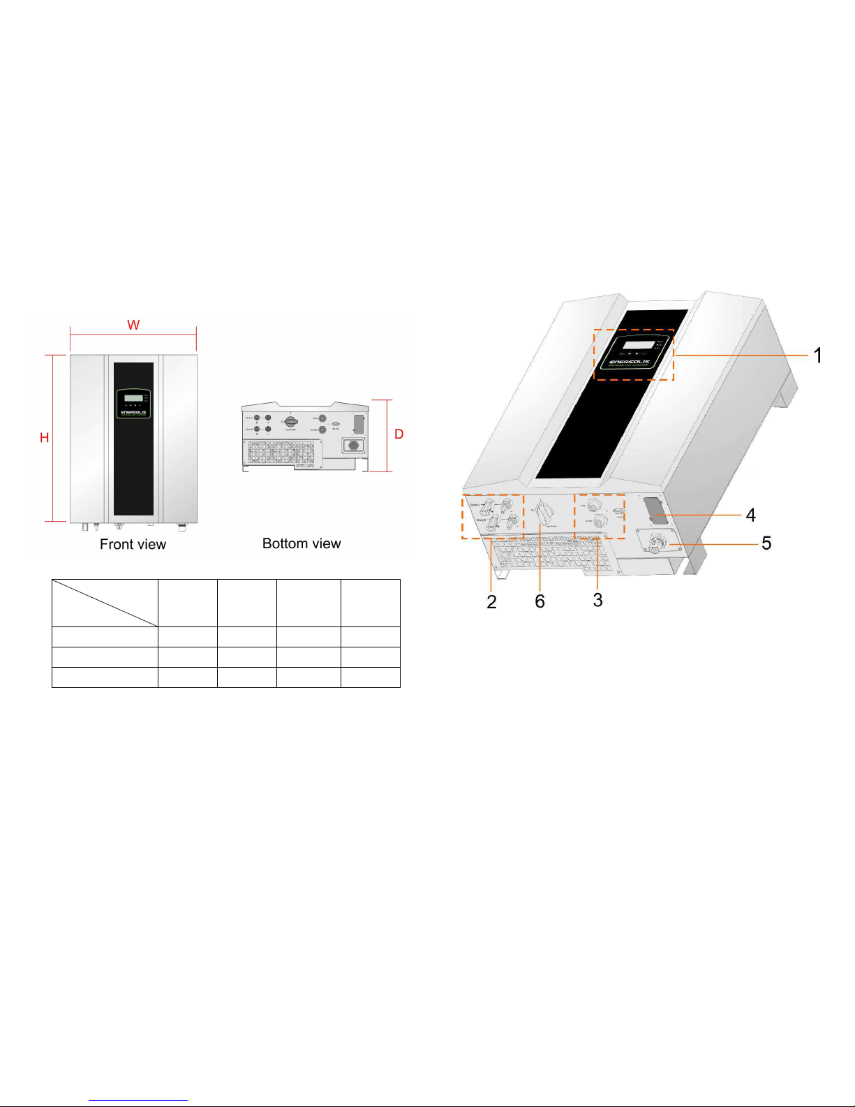
After removing the inverter from the carton check for the following standard
package contents, in addition to the inverter itself.
accessories set (cover, PV connector)
CD-ROM
A wall mount kit set (backrest and backplane positioning paper)
9
4.2
4.24.2
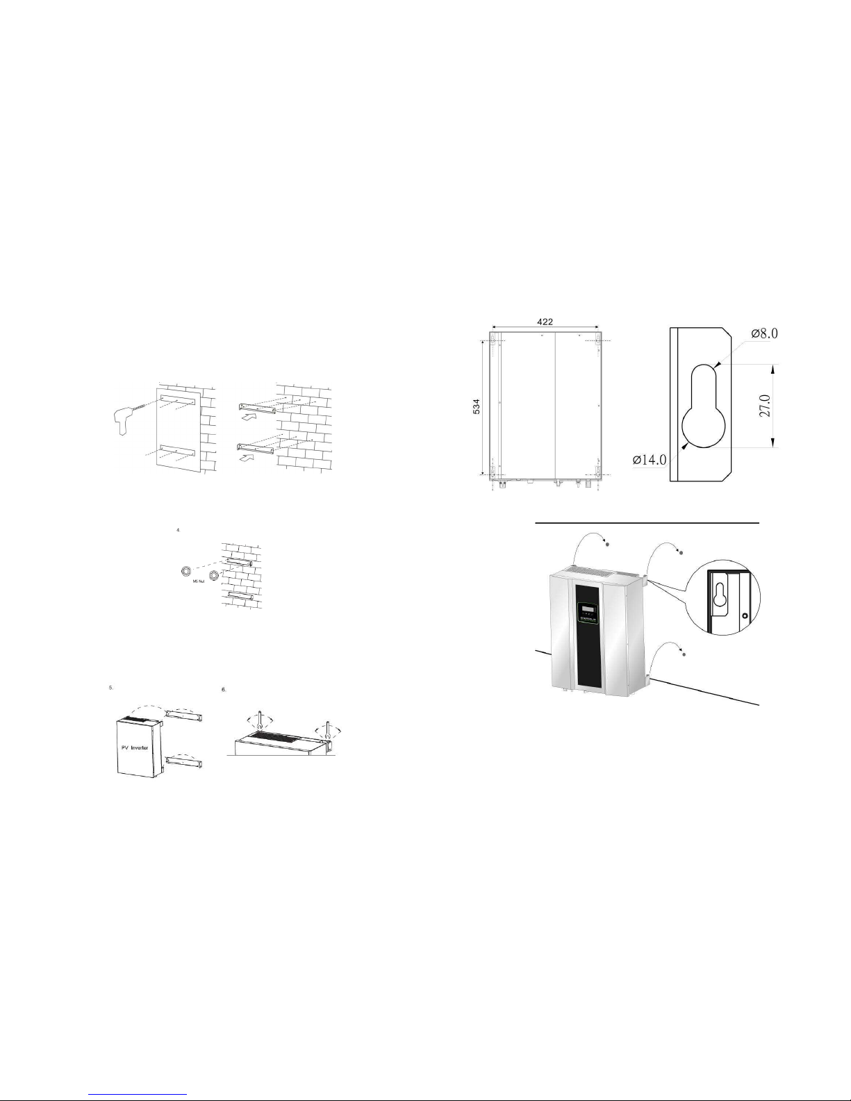
4.2 Installation requirements
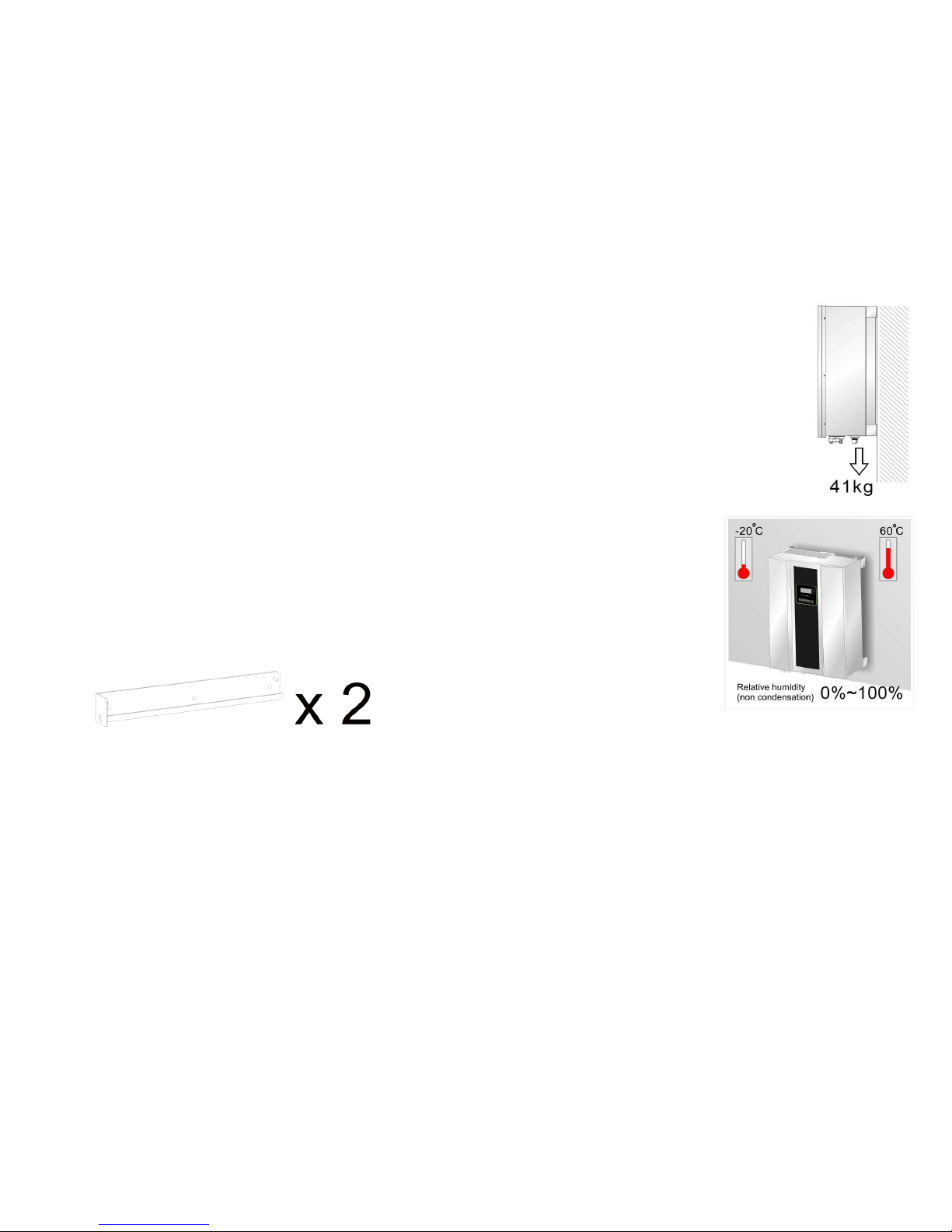
The PV inverter is heavy. Take this weight into account
when choosing the installation site and method of
installation.
To ensure proper operation and long operating life,
position the inverter according to the following
requirements:
(1)
ES 6000(ES 8000/ES 10000/ES
12000) are designed to comply with
Index of Protection class 65, which
allows units to be installed in outdoor
and wet environment . The PV
inverter is designed for outdoor
installation. It should be installed in a
place here it is not exposed to direct
sunlight. The yield of the PV system
may be reduced at increased
ambient temperatures or when installed in poorly ventilated and warm indoor
locations. We recommend an ambient temperature range of -20°C to +60 °C