Installaon instrucons for the OPEN Classic out of pool automac safety cover - 6/20
6
2. Delivery and Recepon
2.1 Delivery
Fig. 6
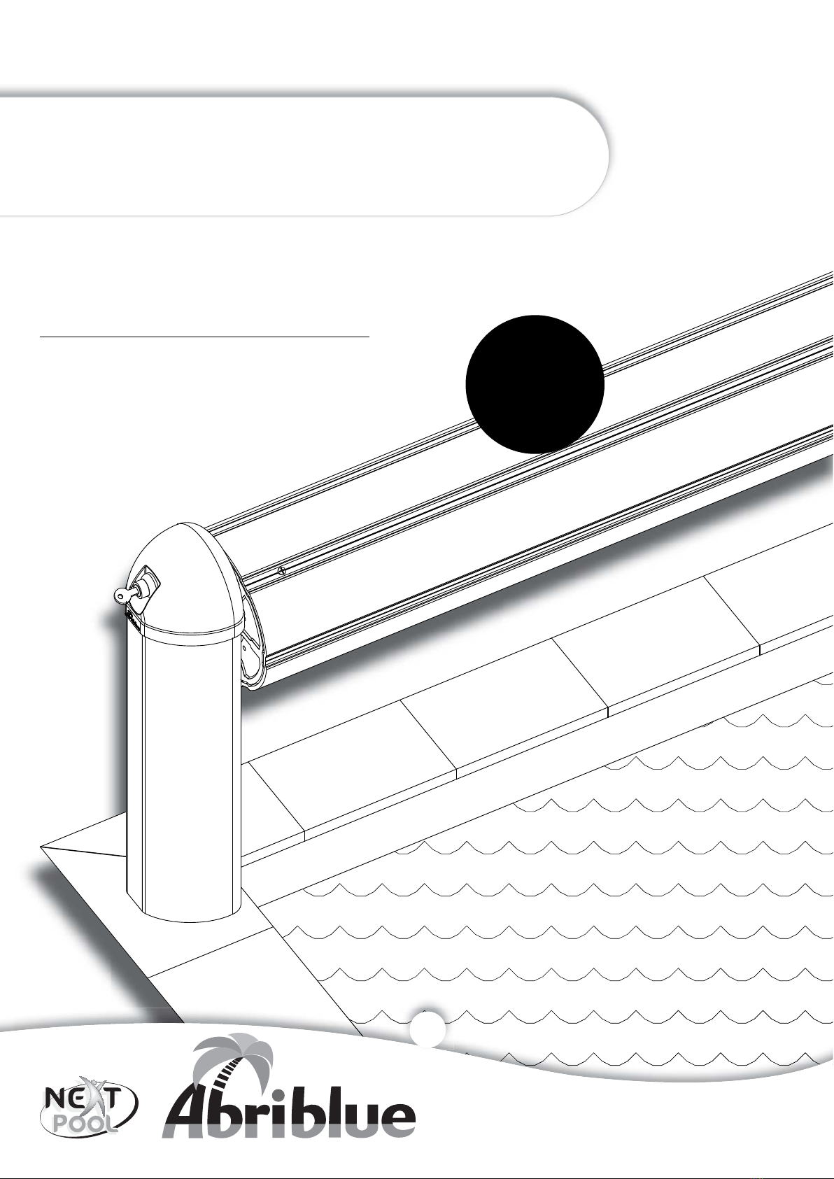
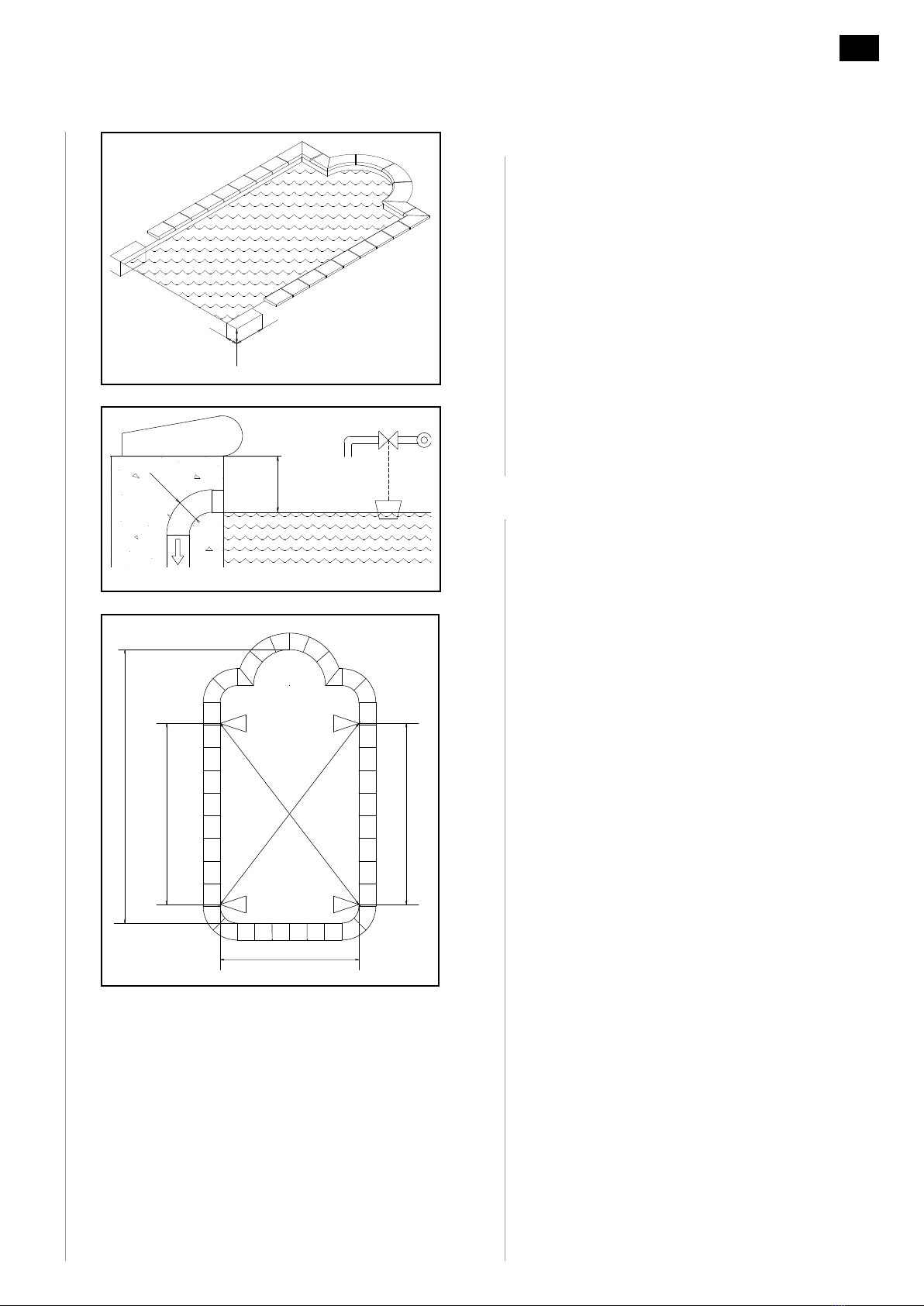
2.1.1 Plan the presence of 2 to 6 persons, or use a
handling device to handle the cover. The cover is
delivered in a non-recoverable wooden container
measuring at least 40 cm more than the width of
the pool. It is heavy and fragile.
2.1.2 For a 4 x 8 pool, the container weighs 290 Kg and
measures 4.6 x 0.6 x 0.8 (h).
2.1.3 For a 5 x 10 pool, the container weighs 390 Kg and
measures 5.6 x 0.6 x 0.8 (h).
2.2 Recepon
2.2.1 Open the container in the presence of the delivery
staffand check the condion of the goods and their
compliance. Keep the original packing.
2.2.2 If there is any damage or missing parts, write
down your reserves on the transport documents
(e.g.: container open on delivery). The words
"subject to unpacking" alone are null and void.
Send a registered leer (with acknowledgement of
receipt) to the transporter within 2 days. This leer
must give an exact descripon of the damage. Send
a copy of the leer to AS POOL for informaon.
2.2.3 Store the parts in the container which should not
be lein full sunlight, but should be placed in a cool
place if the assembly is not carried out on the same
day.
2.2.4 Make the inventory compared to the order.
2.2.5 Read the instrucons completely before starng
the assembly.
2.2.6 The installaon requires 2 persons for 4 hours.
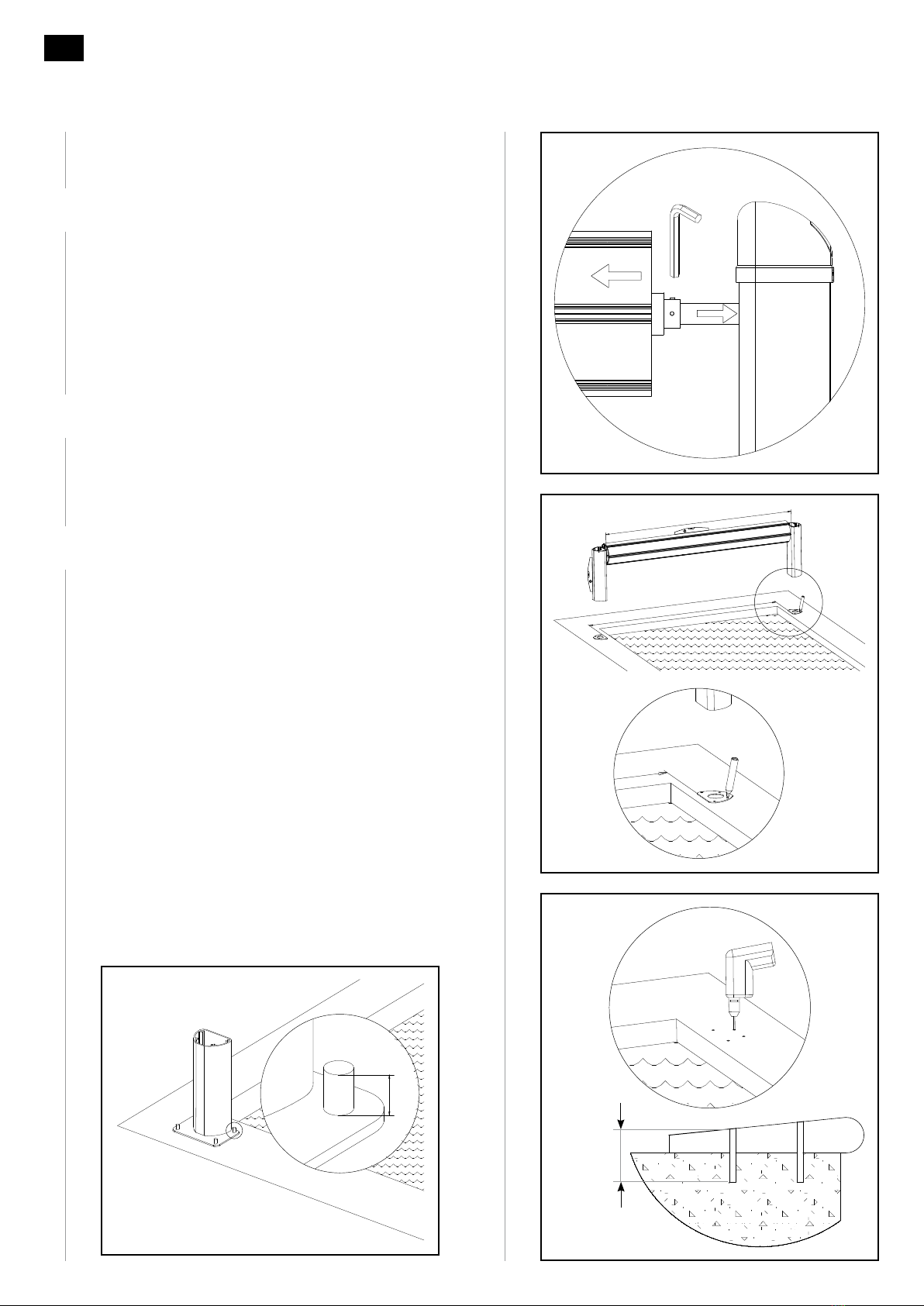
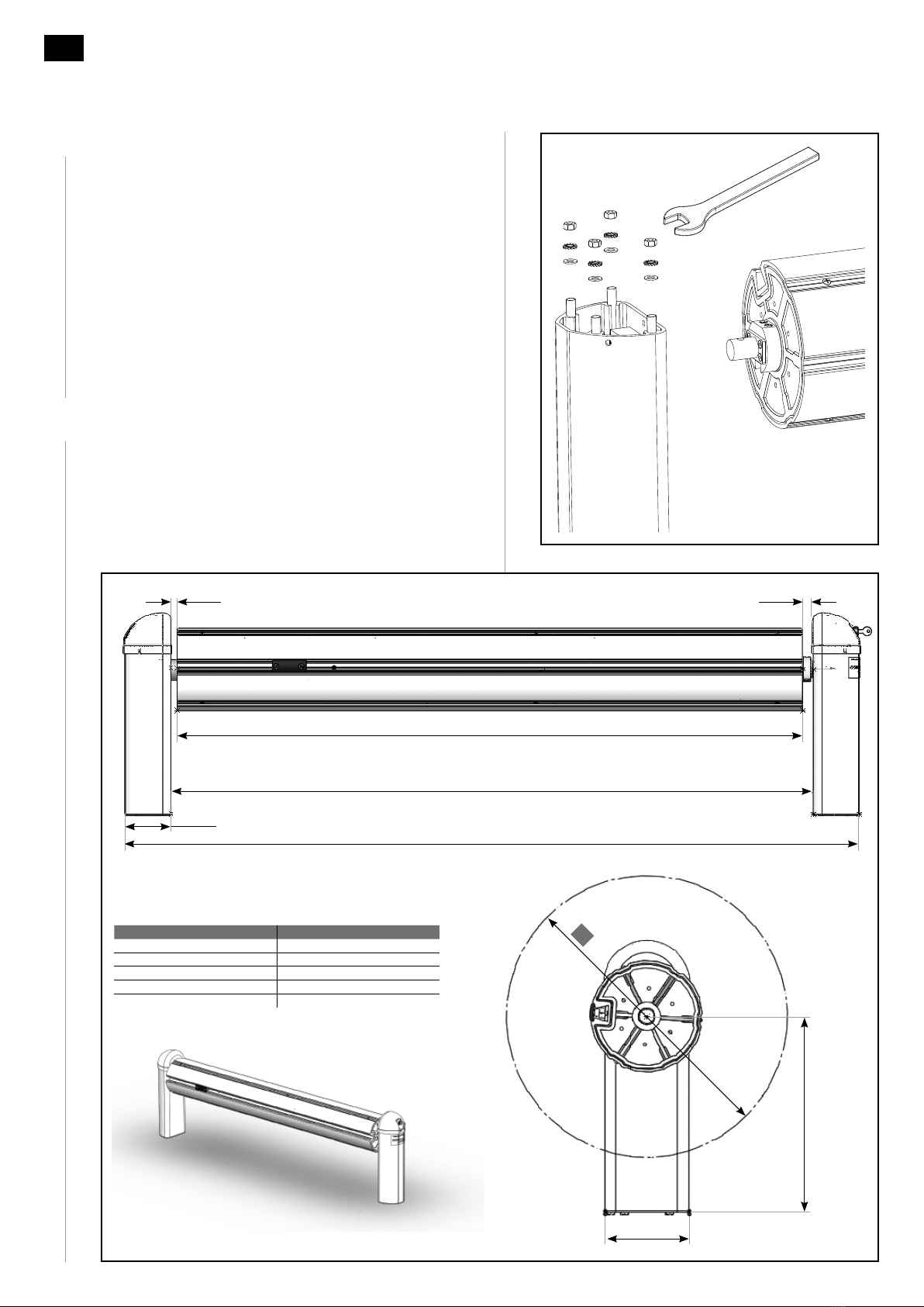
2.3 Necessary tools
Fig. 7
Plan the equipment necessary for assembly: a
perforator, a set of flat spanners, socket wrenches and
hex keys, a set of screwdrivers, a mallet, pliers, a level,
a glue gun, a cuer, a mulmeter, a tape measure, a
grinder, a marker and a saw.
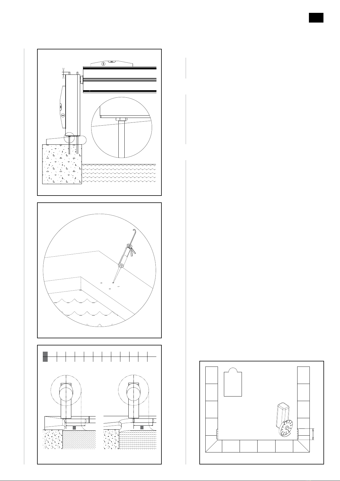
2.4 Items in the container
- A slat apron
- A motorised roller sha
- Two posts to support the sha
- A 19 x 25 cm box
-Afixture kit
- Installaon instrucons
Fig. 7
x 2 4:00
Fig. 6
0.8m
x
0.6m
l4.2 4.7 5.2 6.2 7.2 8.2 9.2 10.2 11.2 12.2
X4.6 5.1 5.6 6.6 7.6 8.6 9.6 10.6 11.6 12.6
0.6 m
0.8 m
x