Resodyn OmniRAM User manual

OmniRAM Installation Manual
Table of Contents
ii
TABLE OF CONTENTS
1.0 Installation Manual Revision Management........................................................................ 1-1
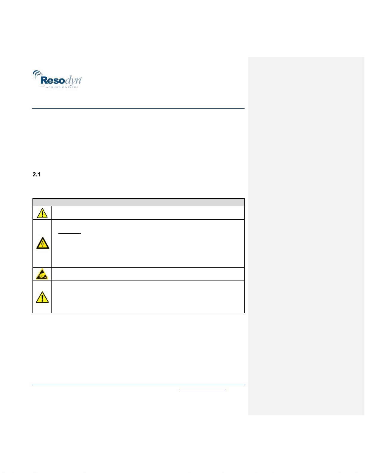
2.0 Safety................................................................................................................................2-1
Warnings and Cautions ................................................................................................. 2-1
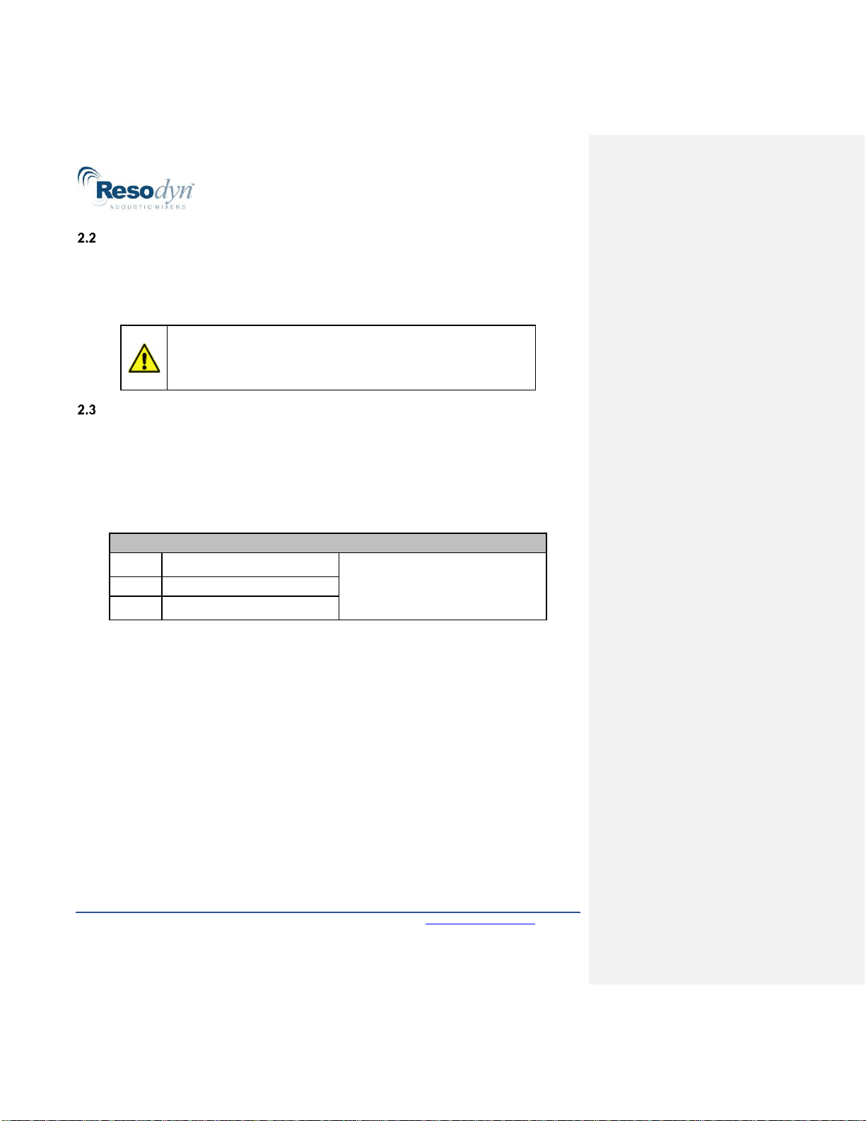
Component Replacement..............................................................................................2-2
Technical Support for Mixer Installation......................................................................... 2-2
3.0 System Installation Overview ............................................................................................ 3-1
Specifications ................................................................................................................ 3-4
4.0 Installation.........................................................................................................................4-6
Shipping ........................................................................................................................ 4-6
Moving the Equipment................................................................................................... 4-6
Leveling the OmniRAM.................................................................................................. 4-6
Installing the Hoist (Optional accessory skip Section 4.4 if not purchased.)................. 4-14
Mounting the Auxiliary Communications Enclosure (ACE)........................................... 4-19
Connect Machine Chilling System ............................................................................... 4-21
Connect Process Heater/Chiller and Process Module (Optional Items)........................ 4-24
Connect Vacuum Module (Optional System) ............................................................... 4-26
Vacuum Pump and Starter Box (Optional System) ...................................................... 4-27
Removing the Shipping Bracket................................................................................. 4-29
Connect Facility Air to the OmniRAM......................................................................... 4-30
Connecting Facility Power to the OmniRAM .............................................................. 4-30
5.0 RAM Basics ...................................................................................................................... 5-1
Operating the OmniRAM ...............................................................................................5-1
LIST OF FIGURES
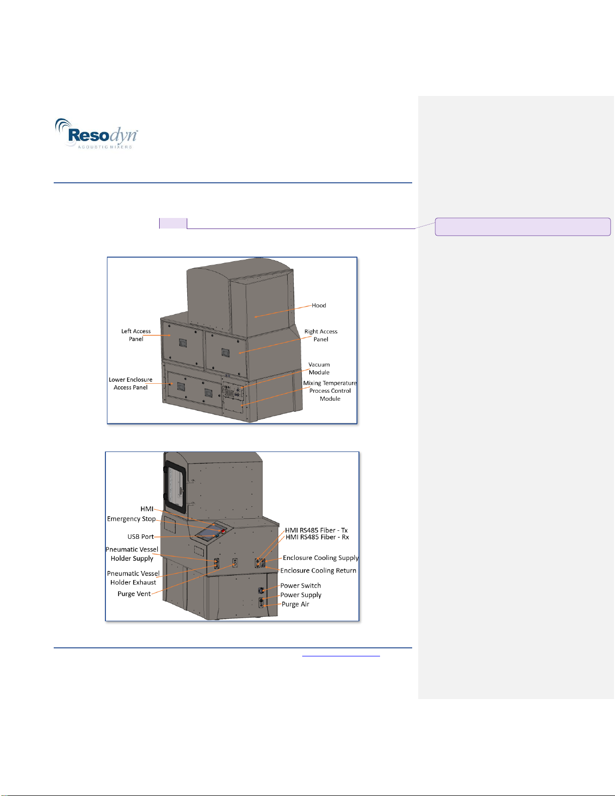
Figure 3-1: OmniRAM Mixer, Rear View, Hood Closed........................................................... 3-1
Figure 3-2: OmniRAM Mixer, Right-Side View......................................................................... 3-1
Figure 3-3: Required Clear Areas Around OmniRAM..............................................................3-2
Figure 4-1: OmniRAM Hoist Attachment ............................................................................... 4-14
Figure 4-2: ACE Bolt Locations............................................................................................. 4-19
Figure 4-3: Vacuum Pump Starter Box Enclosure Bolt Locations.......................................... 4-27
Figure 4-4: Facility Power Connection................................................................................... 4-32
LIST OF TABLES
Table 1-1: Manual Revision History......................................................................................... 1-1
Table 2-1: Warning and Caution Symbols............................................................................... 2-1
Table 2-2: Technical Support for Mixer Installation.................................................................. 2-2
Table 3-1: Figure 3-1 Plumbing and Cable List....................................................................... 3-3
Table 3-3: OmniRAM Mixer Specifications.............................................................................. 3-4
Table 4-1: OmniRAM Pneumatic Hoist Specifications........................................................... 4-17
Table 4-2: OmniRAM Machine Chiller Specifications ............................................................ 4-22
Table 4-3: OmniRAM Process Heater/Chiller Specifications ................................................. 4-24

OmniRAM Installation Manual
Installation Manual Revision Management
1-1
1.0 INSTALLATION MANUAL REVISION MANAGEMENT
Periodically, as required, this document will be updated to correct errors and document
any additional features. Table 1-1 documents the revision, changes, and release date.
Table 1-1: Manual Revision History
Revision
Description
Date
00
Initial Release
02/01/2023

OmniRAM Installation Manual
Safety
2-1
2.0 SAFETY
Every effort has been made to ensure that the OmniRAM is easy to use, reliable, and
safe. This section outlines the general safety considerations and defines caution and
warning symbols used throughout this manual. For safe operation, the OmniRAM must
be operated only within the limits outlined in the system specifications. Acceptable use of
the OmniRAM follows:
•Indoor use only
•Main supply voltage fluctuations do not exceed ±10% of the nominal supply voltage
•Equipment is suitable for continuous operation
Warnings and Cautions
Table 2-1 identifies the symbols used throughout this manual to identify warnings and cautions.
Table 2-1: Warning and Caution Symbols
Warning and Caution Symbols
Caution symbol indicates a potentially hazardous situation that could result in injury
to personnel or damage to the product.
High voltage symbol indicates the possibility of electrical shock.
Turn OFF the electrical supply before removing any cover with this symbol
attached. Failure to do so may cause exposure to electrical shock hazard.
Access to electrical components should only be carried out by a licensed
electrician or qualified electrical engineer.
NEVER attempt to modify any electrical components or circuits. This may affect the
safe operation of the machine.
Electrostatic-discharge sensitive (ESD) components.
Only trained, qualified personnel should remove the access panels.
This equipment should only be operated by trained and qualified personnel.
Do NOT use sharp objects on the touch screen.
Do NOT disable or tamper with any safety items (e.g., safety interlock switches).

OmniRAM Installation Manual
Safety
2-2
Component Replacement
The OmniRAM is designed with components that are specifically rated for use with the
OmniRAM machine. Replace worn, or damaged, components only with direct factory
replacement parts, or parts approved by Resodyn Acoustic Mixers. Incorrect component
replacement can impair the safety of the equipment and risk injury to personnel.
Technical Support for Mixer Installation
The OmniRAM System should be installed as outlined in the Installation Manual. If the
system shows any signs of visible damage during unloading, installation, or fails to
operate as outlined in the User Manual, the system should not be operated.
For installation questions and troubleshooting, see Table 2-2 for Resodyn Acoustic Mixers
Technical Support contact information.
Table 2-2: Technical Support for Mixer Installation
Technical Support
Phone:
+1 (406) 497-5333
Address:
Resodyn Acoustic Mixers
130 North Main, Suite 630
Butte, Montana
Fax:
+1 (406) 497-5206
Email:
Do NOT replace components with non-factory components.
Non-factory replacement parts may not meet OmniRAM
operating requirements, which may compromise the safety of
operating personnel and may cause equipment damage.

OmniRAM Installation Manual
System Installation Overview
3-1
3.0 SYSTEM INSTALLATION OVERVIEW
The OmniRAM is a ResonantAcoustic®Mixer for use in industrial mixing and processing
applications. The OmniRAM consists of a main enclosure that includes a sliding hood,
access panels, and Human-Machine Interface (HMI) (see Figure 3-1 and Figure 3-2).
Optional subsystems that attach to the enclosure include the Hoist, Vacuum Module, and
Process Control Module. The main enclosure and optional attached subsystems ship
assembled, with the exception of the Hoist.
Figure 3-1: OmniRAM Mixer, Rear View, Hood Closed
Figure 3-2: OmniRAM Mixer, Right-Side View
Commented [TF1]: I reworded this sentence for clarity;
please verify it reads correct, thank you.

OmniRAM Installation Manual
System Installation Overview
3-2
The OmniRAM enclosure requires clear areas around the machine that are necessary for
hookups, maintenance, and machine usability. Components and relative location
(including clear areas and connections of the OmniRAM) are depicted in Figure 3-3 and

OmniRAM Installation Manual
System Installation Overview
3-3
Table 3-1.
Figure 3-3: Required Clear Areas Around OmniRAM
Clear areas around the OmniRAM (identified in Figure 3-3) are
required to meet operational, safety, and maintenance needs.
Deviation from clear areas may compromise the safety of operating
personnel and may cause downtime and equipment damage.

OmniRAM Installation Manual
System Installation Overview
3-4
Table 3-1: Error! Reference source not found. Plumbing and Cable List
Color
ID
Description
Notes
Red
1
Machine Power Cable
Customer-supplied cable
2
Vacuum Starter Box Power Supply
Customer-supplied cable
3
Process Vacuum Power Cable
Customer-supplied cable
Orange
4
Serial Fiber Optic Cables (×2)
Supplied by Resodyn; Customer
must specify cable length
Yellow
5
Vacuum Starter Communication Cable
Supplied by Resodyn; Customer
must specify cable length
6
Machine Chiller Communication Cable
Supplied by Resodyn
7
Jacketed Vessel Heater/Chiller
Communication Cable
Supplied by Resodyn
Blue
8
Machine Cooling Supply and Return Hoses
Customer-supplied plumbing
9
Jacketed Vessel Heating/ Cooling Supply
and Return Hoses
Customer-supplied plumbing
Green
10
OmniRAM H Purge Air Supply
Customer-supplied plumbing
11
Vessel Vacuum Supply Hose
Customer-supplied plumbing
12
Optional Vacuum Exhaust Hose
Customer-supplied plumbing
13
Optional Vessel Bleed Exhaust Hose
Customer-supplied plumbing
14
Vacuum Controller Compressed Air Supply
Customer-supplied plumbing

OmniRAM Installation Manual
System Installation Overview
3-5
Specifications
OmniRAM Mixer specifications are outlined in Table 3-2.
Table 3-2: OmniRAM Mixer Specifications
OmniRAM Mixer Specifications
General
Dimensions:
42 in H × 35 in W × 60 in L with no hood (approx.)
70 in H × 35 in W × 60 in L with no hood (approx.)
95 in H × 35 in W × 65 in L with Hoist (approx..)
Mass:
3200 lbs. [1450 kg] (approx.)
Material:
Stainless-steel, with three removable panels
OmniRAM hood:
Slide-open hood with viewing swing-open door
Cooling:
Air-to-liquid cooling
Electrical
Power supply:
1 Phase, 220 to 240 VAC, 40 A, 50/60 Hz
Power consumption:
9.6 kW (under maximum operating conditions)
Circuit breaker:
40 A, two-pole
Electrical enclosure:
Stainless-steel; IP 55 Rated
Three removable access panels
Air-to-liquid cooling
Main Power Disconnect
Switch location:
Lower electrical cabinet
Control fuses:
For protection and isolation of the control circuits
Performance
Maximum acceleration:
100 g
Maximum mix capacity:
11 lbs. (5 kg)
Vacuum rating:
Down to 10 Torr
Controls:
Digital
Data logging capabilities:
1 sample per second
Data recorded includes
(but is not limited to):
Acceleration, Power, Frequency, Vessel Vacuum,
Vessel Temperature, and Time
Controls
Mixer acceleration control (0 g- 100 g)
Configurable mix log data collection for logging custom information entry like lot
number, batch, etc.
Machine parameter display and control
Recipe definition and control
Manual mix timer
Setup and configuration screens for supervisors and administrators
Interlocked Acoustic Enclosure Panels
Cooling System control monitoring

OmniRAM Installation Manual
System Installation Overview
OmniRAM Mixer Specifications
HMI:
PC, with Windows 10 operating system
Alarm display and logging:
Log file records, triggered time, recovered time, and
acknowledged time
User management:
Multiple operator users
User must be logged in to operate the OmniRAM
Log file tracks login attempts
Auxiliary Communications Enclosure
Material:
Stainless-steel; IP 40 Rated enclosure
Dimensions:
12 in [305 mm] H × 10 in [250 mm] W × 8 in [200 mm] D
(approx.)
Mass:
20 lbs. [9 kg] (approx.)
Electrical power supply:
110 - 240 V / 1Φ / 50/60 Hz / 1.0/2.1 A

OmniRAM Installation Manual
Installation
4-7
4.0 INSTALLATION
This Installation Manual details the installation process for the OmniRAM and all standard
options. Instructions pertaining to machine options will be clearly identified and, if not
purchased, can be skipped. Prior to installation, ensure the facility is prepped and ready
for the OmniRAM and all external components. Contact Resodyn (see Table 2-2) if an
installation team, or offsite support, is needed to work with the customer’s facility team
during the installation process.
Shipping
The machine is shipped stripped down and crated. The Mixing Vessel(s), RTD Bridge,
Hoist, and associated equipment are shipped in separate crates.
Moving the Equipment
All pallets and crates can be moved with a standard forklift. The mass of the crated
machine is approximately 3800 lbs. [1730 kg]. The OmniRAM base includes four locking
wheels for moving the unit small distances once removed from the crate.
Leveling the OmniRAM
Adjust the four leveling feet until all wheels are off the ground and the machine is level.
NOTE
OmniRAM is equipped with casters at all four corners to facilitate
movement and positioning. Leveling feet are provided at each
corner to raise the machine wheels and allow for floor variations.
Step 1:
Move the OmniRAM enclosure
into its final operating position.
NOTE: Adhere to the required
clearance areas around
OmniRAM.
Clear areas around OmniRAM are required to meet operational,
safety, and maintenance needs. Deviation from clear-area
requirements may compromise the safety of operating personnel
and may cause downtime and equipment damage.

OmniRAM Installation Manual
Installation
Step 2:
Using a 5/16” Allen wrench and a
half-turn, remove the Lower
Enclosure Access Panel.
Step 3:
NOTE: The wing nuts are located
on the front left and front right side
of the leftmost module.
Remove the two (2) wing nuts
from the Amplifier Module.
Place the wing nuts in a safe
location (they will be required
when reinstalling the Amplifier
Module).
Step 4:
Disconnect the four (4)
connections to the Amplifier
Module.
Pushing up on the tab, disconnect
the two (2) I/O connections.
Then, disconnect the coolant and
return quick-connects (red hoses).

OmniRAM Installation Manual
Installation
Step 5:
Without removing it completely,
slide the Amplifier Module tray to
its outmost position.
Step 6:
Using a 5/16” wrench, loosen the
bolt just behind the back of the
opened drawer.
NOTE: This will allow the
raising/lowering of the leveling foot
at the end of the threaded rod.
Step 7:
Using a 5/16” Allen wrench, adjust
the leveling foot to raise the caster
off the floor.
IMPORTANT: This step will be
repeated for all four OmniRAM
wheels until they are off the
ground.
Level the machine with additional
adjustments to the feet, until the
machine is level within 5/8” front-
to-back, and 3/4” side-to-side.
When complete, tighten the bolt to
lock the leveling feet.
Commented [TF2]: Hand-tighten? Or is a tool needed?

OmniRAM Installation Manual
Installation
Step 8:
With the tray pulled all the way
out, repeat steps 6 and 7 with the
bolt in the back of the machine.
Step 9:
Moving to the opposite side of the
OmniRAM, use a 5/16” socket to
loosen the eight (8) outside bolts
on the Mix Process Control
Module.
IMPORTANT: Do NOT remove
the Process Control Module yet.
NOTE: The Process Control
Module is an optional accessory, if
it hasn’t been purchased, a cover
plate will be in its place and step
10 can be skipped.
Step 10:
Disconnect the three (3)
connections to the Mix Process
Control Module.
Reach through the opening to
behind lower access panel,
disconnect the one (1) I/O
connection.
Finally, disconnect the two (2)
Coolant quick-connects (red
hoses).

OmniRAM Installation Manual
Installation
Step 11:
Remove Mix Process Control
Module.
NOTE: Do NOT lose attachment
hardware. The bolts and washers
will be required when reinstalling
the Mix Process Control Module.
Step 12:
Using a 5/16” wrench, loosen the
bolt made visible by the removal
of the Mix Process Control
Module.
NOTE: This will allow the
raising/lowering of the leveling foot
at the end of the threaded rod.
Step 13:
Using a 5/16” Allen wrench, adjust
the leveling foot to raise the caster
off the floor.

OmniRAM Installation Manual
Installation
Step 14:
Repeat steps 12 and 13 with the
bolt in the back of the machine.
Step 15:
When all four OmniRAM wheels
are off the ground, level the
machine with additional
adjustments to all four leveling
feet until the OmniRAM is level
within 5/8” maximum front-to-
back and 3/4” side-to-side.
Step 16:
When the machine leveling is
complete, tighten the leveling foot
bolt on all four corners to lock the
leveling feet.
Tighten the locking nuts after
leveling machine.
Commented [TF3]: With a tool or hand-tighten?

OmniRAM Installation Manual
Installation
Step 17:
Install the Mix Process Control
Module by using a 5/16” socket to
install the eight (8) outside bolts
and washers on the Mix Process
Control Module.
Tighten to 27 inch-pounds.
Step 18:
Reconnect the connections to the
Mix Process Control Module by
connecting the one (1) I/O
connection, and the two (2)
coolant quick-connects (red
hoses).
Step 19:
Slide the Amplifier Module back
into place.
Secure by reinstalling the two (2)
wing nuts.
Commented [TF4]: What tool is needed?

OmniRAM Installation Manual
Installation
4-15
Installing the Hoist (Optional accessory skip Section 4.4 if not purchased.)
The OmniRAM can be purchased with a Manual or Pneumatic Hoist attachment (Figure
4-1) that ships separately from the machine. The installation instructions outline the steps
to mount the Hoist on the OmniRAM, and apply to both the Manual and Pneumatic Hoists.
Additional installation steps specific to Pneumatic installation are addressed in Section
4.4.2.
Figure 4-1: OmniRAM Hoist Attachment
General Hoist Installation Steps
Before installing the Hoist, verify the OmniRAM is level, as outlined in Section 4.3. These
steps apply to both the Manual and Pneumatic Hoist.
Step 1:
Place the Spacer against the Lower
Enclosure.
Line up the bolt holes in the Spacer
with the holes in the Lower
Enclosure.
Apply 243 Loctite®, or equivalent, to
the bolts.
Secure the Spacer in place using
the six (6) washers and bolts.
NOTE: Orientation of spacer: The
Spacer’s angled face should be
towards the front of the machine.
Use a 1/2” wrench to torque the
bolts to 11 ft-lbf [14.9 Nm].
Commented [TF5]:
Table of contents
Other Resodyn Laboratory Equipment manuals
Popular Laboratory Equipment manuals by other brands

Agilent Technologies
Agilent Technologies 280-DS MQS Operator's manual

Civco
Civco ASTRA TEE A6172-01 installation manual

ibidi
ibidi 12110 instruction manual

Gilson
Gilson Pipetman P2G user guide

Dynamica
Dynamica VELOCITY 14 Pro instruction manual

NuAire
NuAire LabGard NU-640-400 Operation and maintenance manual

Opsytec Dr. Grobel
Opsytec Dr. Grobel BS-02 manual

Labconco
Labconco FreeZone 7750000 user manual

GR Scientific
GR Scientific Aquamax KF user manual

VERDER
VERDER Carbolite Gero HTMA 4/28 Installation, operation and maintenance instructions

Hettich
Hettich ROTINA 420 manual

Optics11
Optics11 DELTASENS user manual