Dirui CS-T240 User manual

1
Content
List ....................................................................................................................................................1
Chapter 1 Instrument specification ...................................................................................................2
Chapter 2 Installation........................................................................................................................9
Chapter 3 Performance and test flow..............................................................................................12
Chapter 4 Module Instruction……………………………………………………………………..21
Chapter 5 Instrument Fluid Pipeline………………………………………………………………33
Chapter 6 Instrument Hardware Circuit…………………………………………………………..41
Chapter 7 Maintenance……………………………………………………………………………56
Chapter 8Analysis Method………………………………………………………………………..72
Chapter 9 Troubleshooting List……………………………………………………………………84
2
Chapter ⅠInstrument Specification
1.1 CS-T240 Model Specification
1.1.1 Product Composition:
The analytical part (host), operation part (computer system), the result output part, accessories and
consumables.
Product applicable scope: used for quantitative analysis of serum, plasma, urine, cerebrospinal
fluid and other clinical chemical constituents of sample.

3
1.1.2 Front ①②
①Model Logo
②Upper Cover
③Front Cover
③
1.1.3 Rear
①Purified Water Inlet
②Low Concentrate Waste Outlet
③High Concentrate Waste Outlet
④Detergent Inlet
⑤Detergent Level Sensor Port
⑥Left Back Cover
⑦Syringe Pump
⑧Right Back Cover
⑨R S232 Port
①②③ ④⑤⑥⑦⑧⑨

4
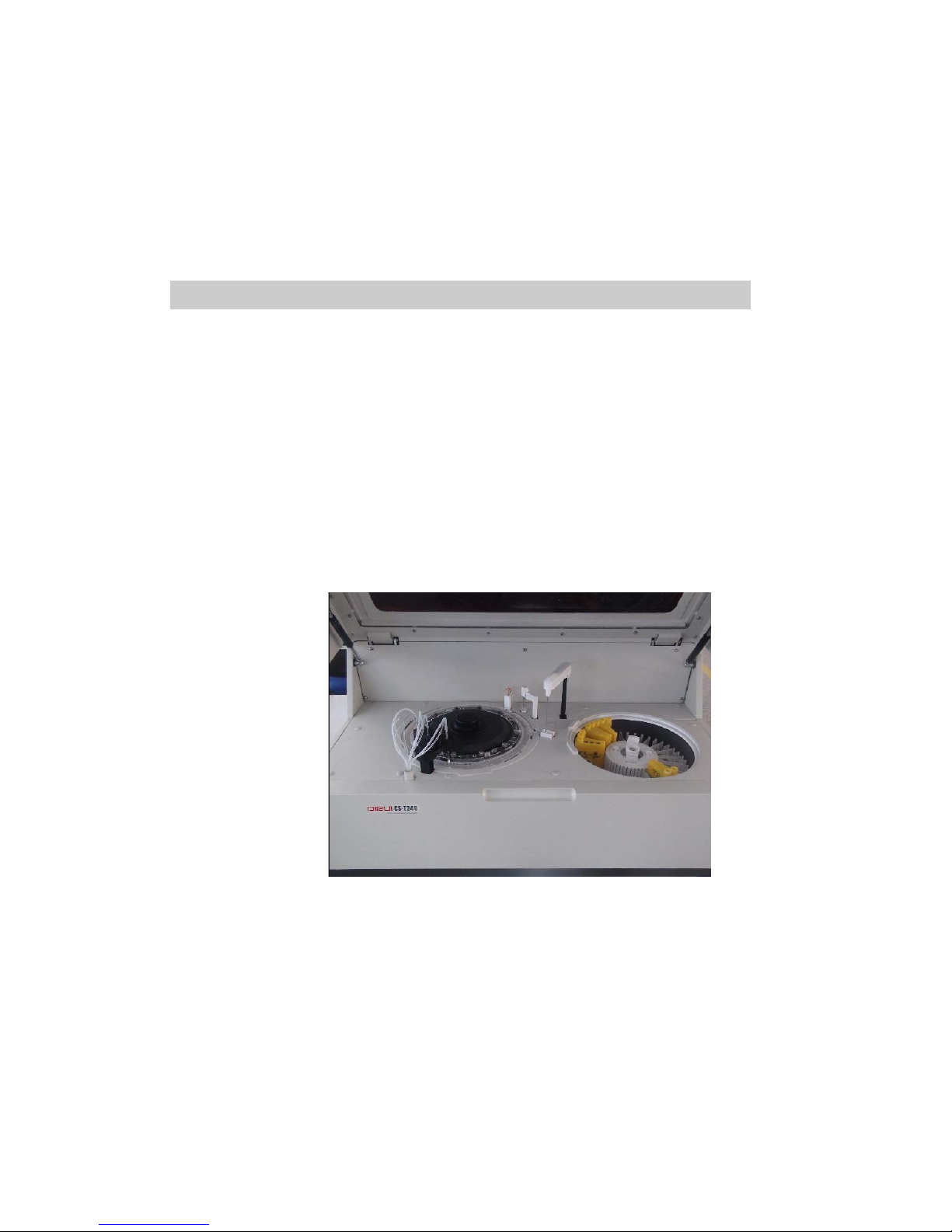
1.1.4 Working Table
①Reaction Cuvette Rinsing Unit
②Reaction Disk Unit ① ② ③ ④ ⑤ ⑥
③Reaction Tank Liquid Level Detection
④Stirring Unit
⑤Sample &Reagent Adding Unit
⑥Sample & Reagent Disk
⑦Mixer Rinsing Tank
⑧Probe Rinsing Tank
⑦⑧
1.1.5 Rightside
①Main Switch
②Power Socket
③Fuse Installation Place
④Main Power Indicator(Red)
⑤Refrigeration Power Indicator(Green)
⑥Analysis Unit Switch(exclude refrigeration power)
①②③④⑤⑥

5
1.2 Analysis Unit
The working speed of CS-T240 auto-chemistry analyzer is 240 tests / hour at constant speed
(single / double-reagent item), whose working period is 15 seconds. Instrument overall structure
adopts the project of "2-disks + 1-probe + 1-stirring rod"—one reaction disk, one sample &
reagent disk, one stirring rod, one sample & reagent probe used for adding reagent and sample,
one stirring rod used for mixing. "Grating + diode array" approach is adopted in optical
measurement unit for real-time optical collection of reaction cuvette. The 8-stop 12-step
automatically rinsing of the reaction cuvette is carried out during testing process.
1.2.1 Structure
1.2.2 Reaction Unit
Reaction Cuvette Reaction Disk
Reaction cuvette:120,optical path: 6mm
20×6 sets hard optical plastic cuvette
Incubation bath
Digital liquid sensor
8-stop 12-step rinsing of colorimetric cup

6
1.2.3 Probe and Stirring Unit Stirring Unit Probe Unit
Probe unit:1
sample & reagent probe
High-precision digital liquid detector
Stirring Unit:1
High-speed hollow cup motor
Surface high-intensity Teflon coating
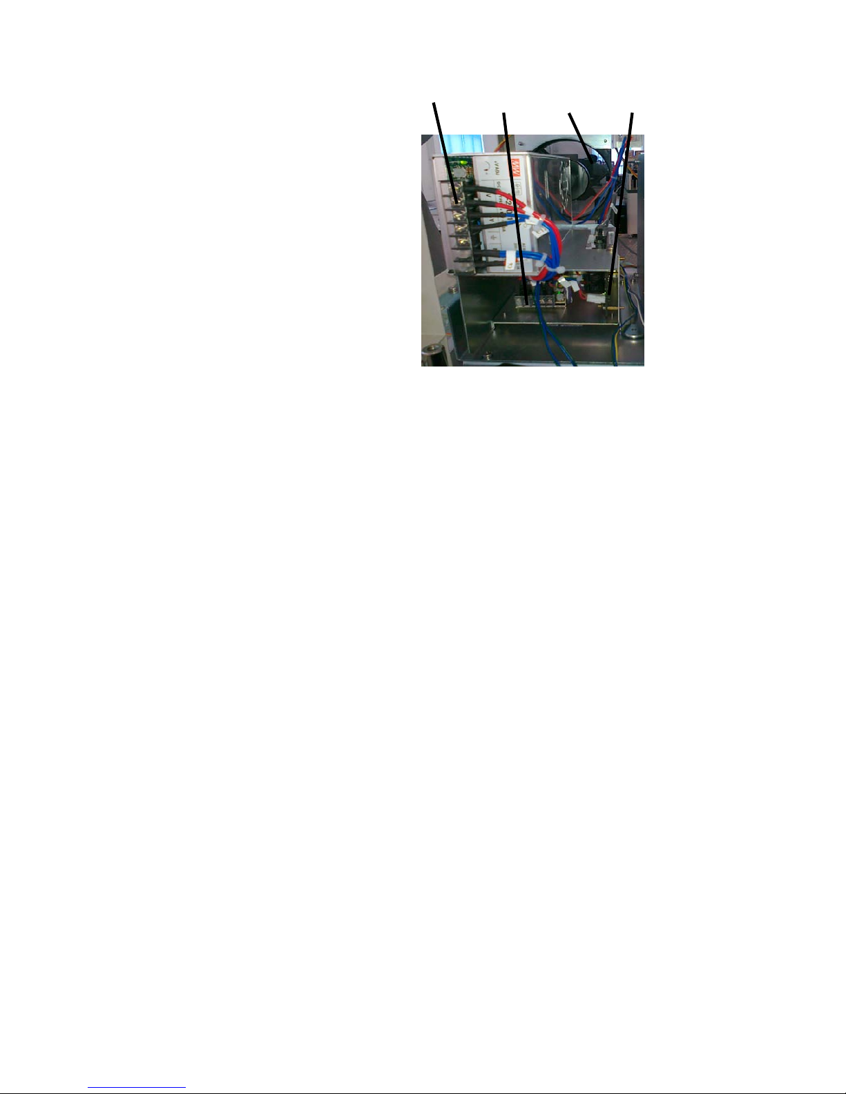
1.2.4 Control unit1
Circuit panel boxes: 5 panels ①
Order: from left to right
ISE control panel(Optional)
Sample reagent disk control panel ②
Rinsing & stirring control panel
Reaction disk control panel
Main control panel
②Switching Power Supply Box: 3
Order:form outside to inside
+12V(lamp)
+5V(digital circuit)±12V(simulation)
+24V(motor, valve)
③Circuit panel box power supply interface ③④⑤⑥⑦
④halogen lamp power supply control interface(+12V)
⑤Cooling unit power interface(220V)
⑥Fan power interface(220V)
⑦Solid state relay panel interface(220V)
7
①②③④
1.2.5 Control Unit 2
Semiconductor refrigeration system:
①+12V refrigerator power
②+5V control panel power
③Fan(15W/220W)
④Control panel(with status indication)
8
1.3 Function Overview
Main work flow:
1. All mechanical moving parts initialization.
2. 3 times water blank measure is implemented after six time automatic rinsing
3. Sample reagent probe assimilates quantitive reagent when it descents to reagent sample disk
after the sample reagent disk rotates to designated R1 reagent position. And then, sample reagent
probe assimilates quantitive sample when it descents to reagent sample disk after the sample
reagent disk rotates to designated sample position.
4. After 8-stop 12-step rinsing, reaction cuvette stops at the sampling position, and sample reagent
probe rotates to reaction disk and descends to reaction cuvette to discharge the mix liquid(reagent
and sample), the reagent 1 and sample adding is finished.
5. Reaction cuvette is stirred immediately when it rotates to R1stirring position.
6. Sample+R1 reagent react in reaction cuvette or temperatured.
7. If it is double reagent item test, sample reagent disk rotates to the designated R2 reagent
position and sample reagent probe descends to sample reagent disk to assimilate quantitive reagent
after a set period (6 mins).
8. The sample&reagent probe discharges R2 into reaction cuvette when it rotates to reaction disk.
9. Finishing R2 reagent adding, reaction cuvette is stirred after its one circle (R2 stirring position)
rotation.
10. Reaction cuvette carries out the collection of absorbance data when it passes the optical unit in
every period.
11.The reaction cuvette is rinsed automatically after reaction when passing the rinsing unit, and 15
minutes have been elapsed since sampling to rinsing.
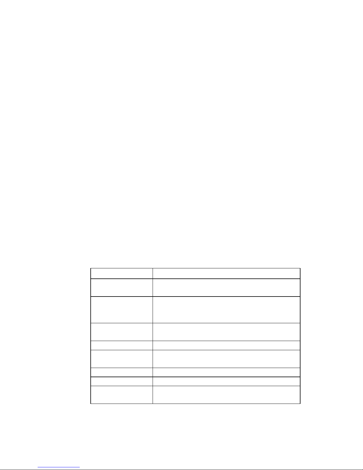
Table 1-3-1 Main Function of Each Unit
Name Main function
Sample&reagent probe
unit
Execute sample, reagent assimilation and discharge of all
biochemical items and ISEitems
Sample&reagent disk
unit
Total 21 sample positions for carrying all test samples,
standard solution and control, 46 reagent
positions for
carrying test reagent and detergent
Reaction disk unit Total 120 reaction cuvettes used as container of
reaction
and colorimetry test.
Reagent stirring unit Stirring when reagent is added into reaction cuvette.
Optical
system groupware
Measure 12 wavelength absorbance by grating system
Auto-rinsing unit Rinse reaction cuvette automatically by 8-stop 12-step
ISE unit (optional)Carry out ISE measurement (K、Na、Cl)
Barcode Total 1 for scanning reagent and sample bottles in sample
reagent disk

9
Chapter 2 Installation
2.1 Space Requirement:
To make sure the space of maintenance, operation and repair, please follow the instruction as
below:
●Space between left (right) side of analyzer and the wall should ≥50cm
●Space between rear board of analyzer and the wall should ≥50cm
●Space in front of analyzer should≥100cm
●Make sure there is enough space for waste device and purified water equipment.
2.2 Power supply requirement:
●Power supply: AC220V±22V 50Hz/60Hz
●Power: 650VA
●Circuit breaker: 250V, 20A
A well grounded power supply socket is a must. Large electrical appliance such as air condition,
refrigerator, even cannot use the same socket with analyzer.
△! Warning:
Incorrect grounding may cause electric shock or instrument damage.
Input voltage should conform to requirement. 3KVA-line UPS power supply is advised.
2.3 Environment requirement
●Working temperature: 15℃~32℃
●Relative humidity: 32 %~85%
●Atmospheric pressure: 76kPa~106kPa
●Environment should with no dust, vibration, major noise source and power interference
●Do not put the analyzer in the vicinity of brush motor, flicker fluorescent tube and other
constant on-off electrical equipment.
●Hard and flat ground is a must for the instrument.
●Avoid direct sunlight, do not put the analyzer in front of heat source and wind source
●Keep good ventilation.
△! warning:
Normal running and accurate result can not be guaranteed if instrument works beyond the
requirements mentioned above.

10
Please use air conditioner if the temperature or humidity can not meet the requirement above.
The heat generated during working process by the instrument will be emitted at the rear of the
instrument. Good ventilation should be kept well and ventilation equipment can be adopted if
necessary, but direct air current should be avoided, or inaccuracy of instrument test may be
caused.
2.4 Purified water equipment:
①water should be obtained from tap water pipe
②water conductivity should within 1uS/cm
③water supply volume should reach 40L/h or more
④The hydraulic pressure should within 49-343 Kpa
2.5 Instrument Installation Flow:
Make sure the installation place, space, electrical environment, installation room temperature and
purified water equipment can conform to requirements
Make sure instrument installation tools needed are complete and reagent and QC liquid are
enough.
Please check the prepared items according to packing list when open the package; please write
them down on the check report if any missing.
Place instrument in appropriate position, and mount with computer host, display and printer.
Connect water supply and waste liquid outlet equipment.
Infuse CS-anti-bacterial detergent into the 45th position of sample reagent disk.
Check whether the power and data wires are well connected
Install sample reagent probe and reaction cuvette
Check whether the sample reagent probe can move up and down flexibly
Get through the pure water machine, computer host, display and analytical unit power supply, and
enter CS auto-chemistry analyzer systematic application software. Initial user name: 001, initial
password: 001.
After enter software, follow the steps below in “Maintenance” interface.
(a)Injection pump exhaust
Execute injection pump exhaust to expel air in pipeline.
(b)Cleaning liquid pipeline exhaust
Executing irrigation detergent pipeline exhaust is infusing detergent into pipeline to expel air in
pipeline.
(c)Reagent&sample probe horizontal check
Make sure sample&reagent probe is right above reaction cuvette, rinsing groove and reagent
bottle.
Place two standard cups at outer circle position 43, inner circle 44 respectively in the sample&
reagent disk, and put two blank bottle in inner circle 2 and outer circle 1.Make sure the sample&
reagent probe is above reaction cuvette, rinsing groove, standard cup by implementing reagent
sample probe horizontal check.
(d)Stirring rod horizontal check
In order to make sure the stirring rod is above the reaction cup, rinsing groove.

11
(e)Mechanical movement check
Execute 20 times mechanical movement checks to make sure whether the washing block of
rinsing mechanism nozzle abrases the reaction cuvette or not and each mechanism runs normally
or not.
(f)Rinse reaction cup+ ISE
Select rinsing reaction cuvette in “Maintenance” interface, and execute rinsing reaction cuvette +
ISE if ISE equipment is collocated.
(g)Light quantity check
Light quantity result should be attached to installation check report with its value no more than
18000.
(h)Cup blank test
No.1 cup blank value should be within 18000, and 2-120 reaction cup check value should be
within 18000 ±800.
2.6 Clinical item test
Edit chemical parameters; register reagent info.; testing rate assay ALT, point assay, two-point
rate BUN; calculate the difference of parameter and the result of test should be attached to
installation check report.
2.7 Train Medical Personnel
2.8 Fill the Installation Check Report Detailedly.
12
Chapter 3 Performance and Test Flow
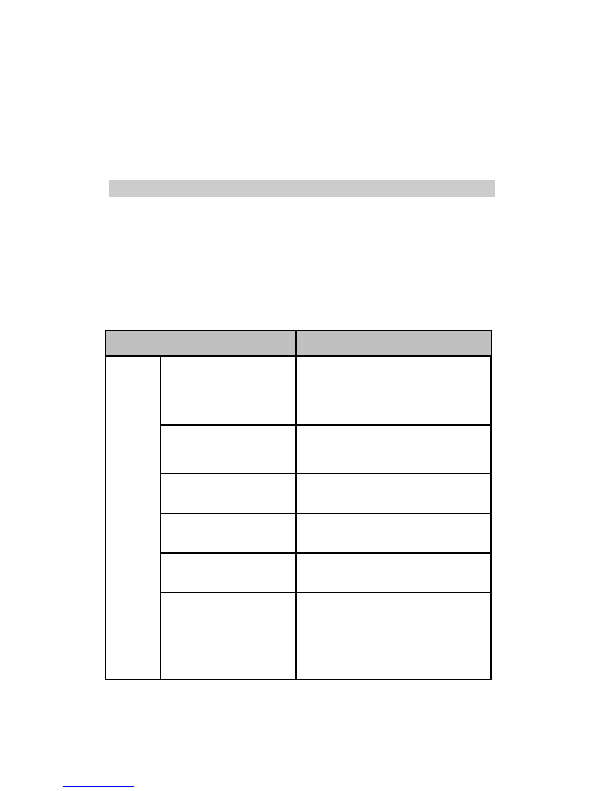
3.1 Main Performance Index
3.1.1 Instrument standard specification
Performance Index Standard Specification
Characteri
stics
Wavelength range
Grating rear spectrophotometry system,
simultaneous photometric processing of 12
wavelength:340 、380 、405 、450 、480
、
505 、546 、570 、600 、660 、700 、750nm
Wavelength
precision ±2nm
Reaction
temperature 37℃±0.1℃
Test item
Simultaneously testing 60 colorimetric items
and 3 ISE items at most
Test
method Rate assay ,end-point assay, 2-point assay.
Test
speed
Constant speed, 240 tests/ hour ( 360 tests/
hour
speed with ISE)

13
Reagent
sample
system
Sample & reagent disk,sample
position, reagent position
Reagent & sample disk with refrigerator,
semiconductor cooling system.Total 67
positions(21 routine samples, 45 reagent
positions “CS-bacterial phosphate-free
detergent”, 1 detergent position)
Sample type Serum, plasma, Urine,
cerebrospinal fluid,
ascites and other body fluids
Sample volume 3~35ul,0.1μl incremental
Test tube
Test tube Φ(12-16)mm×(75-100)mm(±1
mm)
Standard cupΦ14mm×37mm(±1 mm)
Remaining sample volume More than 100μl
Sample&reagent probe With liquid le
vel detection and collision
detection function
Sample&reagent probe rinsing Inner, outer wall rinsing
Sample&reagent liquid level
sensor
Digital liquid detecting, integration
with sample&reagent probe
Reagent volume 10~350ul,1μl incremental
Reagent bottle 20mL 、70mL、100mL
Remaining reagent volume More than 3mL
Reagent storage temperature 5℃~15℃
14
Barcode information
type:code 128
Size:
width: 8-12mm; alid length : within
40mm; start blank and finish blank:
within 3mm when cutting.
Sticking requirement:the lower edge of barcode
should be within 15mm-20mm away from the
test tube bottom
to make sure right reading
barcode,and make sure the barcode is aligned
with sample position gap when putting the test
rack.
Reacti
on System
Reaction cuvette mode Discrete
Reaction cuvette
optical path 6mm
Reaction cuvette number 6 sets, 20 for each,total 120
Reaction time 15 mins
Reaction liquid volume 150~550ul
Light source 20W/12V Long-life quartz halogen lamp
Absorbance range 0~3.3ABS
QC QC interval, monthly QC
Automatic rinsing Automatically rinsing reaction cuvette, sample&
reagent probe, stirring rod.
Stirring system separately stirring after adding
Data
system
port TCP/IP network port,standard RS-232 and USB
2.0 port
Printer Stylus printer, supporting the user-defined mode
for report sheet
Connecting LIS/HIS system LIS/HIS system available
Instrument
system
weight About 120Kg
Dimensions 998*752*515 (length×width×height)
15
power(VA)650VA
Water consumption 5L/小时
Installation
requireme
nt
power 220V/230V,50Hz/60Hz,1000VA
Using environment Systems storage temperature : 0℃~40℃,
volatility: <±2℃/H; storage humidity:30%RH~
80%R ,non-condensing ;at
working,
temperature:15℃~30℃, volatility<±2℃/H;
atworking, relative humidity:35%RH ~
80%RH ,non-condensing ;
not higher than
2000 meters above sea level.
3.1.2 Testing speed
Test conditions Degree of reduced ability to process (estimated)
Retest after sample
prediluted
80 tests/h(all tests after predilution )
Use avoiding cross
contamination function
120 tests/h at least(reaction cuvette、sample reagent probe)
R1 and R2 items are
used simultaneously in
testing
240 tests/h at least
16
3.2 Test Flow
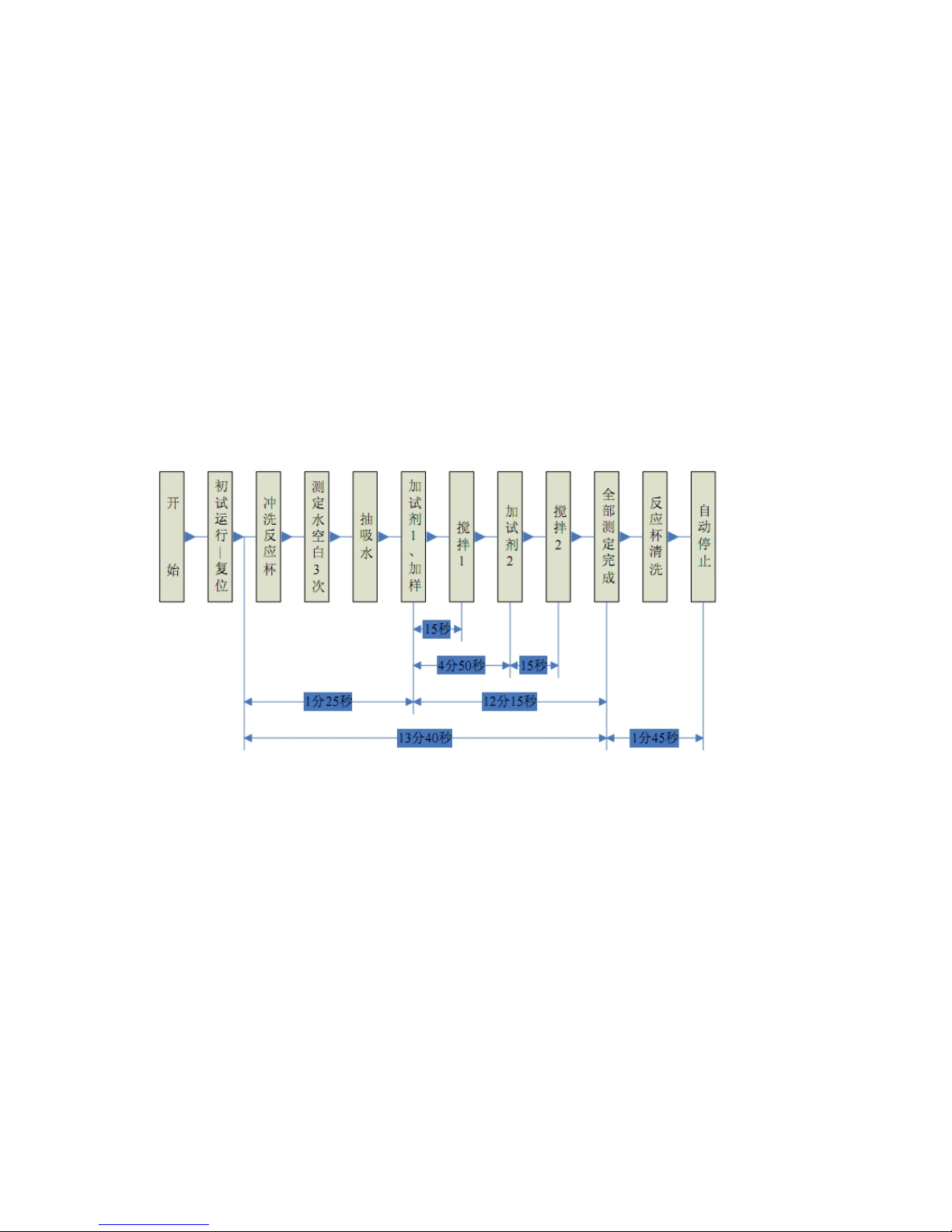
3.2.1 典型测试流程

17
3.2.2 Test Flow Instruction
1. Periodic movement sequence of sample reagent probe
a. Switch the pump to zero, internal and external wall rinsing
b.Inhale 3ul air.
c.Rotate to the position above the sample reagent disk
d.Descend till the sample&reagent probe point into liquid level about 2mm
e. Assimilate quantitive volume + push back redundant sample
f.Move to above the rinsing pool from the reagent bottle to rinse the external wall.
g. Inhale 3ul air
h. Move to above the sample&reagent disk
i. Assimilate quantitive volume sample
j.Move to above the reaction disk from sample cup or tube
k.Add sample and reagent into the reaction cuvette
l. Rotate to above the rinsing pool from reaction cuvette
→ (next periodic movement sequence).
2. Stirring rod periodic movement sequence:
a.Rotate to above reaction disk
b.Descend into reaction cuvette
c.Mix reaction liquid
d.Rise from reaction cuvette and rotate to rinsing bath
e.Descend into rinsing bath
f.Stirring rod rinsing
g.Rise from rinsing bath
3. Movement and time sequence of reaction disk
A track includes total 120 reaction cuvettes in reaction disk, and rotates in a fixed way when
testing. The reaction cup always rotates and stops 4 times counterclockwise, total 36+4+
82=122 (rotation and stop sequence 36-4-82)patches, in every working period, 15
seconds elapsed.

18
figure 3-2 Position of reaction disk and probe
Outer circle figure: No. of reaction cuvette;inner circle figure: No. of mechanism position.
Reset point is in 71 position of reaction disk.
Reagent1、2 and sample probe is in NO.1 position, stirring is in No.3 position.
Reaction cuvette rinsing unit: NO.71、73、81 position
Reaction cuvette rinsing sequence:
1 → 3 → 5 → 7 → 9 → …… →117 → 119 (18 mins,60 times)
2 → 4 → 6 → 8 → 10 → …… → 118 → 120 (18 mins,60 times)
加试剂与加
样位置
120 个反应杯位置号
搅拌位置
参考位置编号
光电检测位
反应盘复位点
反应杯清洗机构

19
i. Reaction Cuvette Rinsing Movement Sequence
figure 3-3 Reaction cuvette rinsing probe position
Above figure shows that 8 steps are needed when rinsing reaction cuvette. (3 times cell blank test
is added) , therefore, to finish rinsing one reaction cuvette, 12 steps are needed:
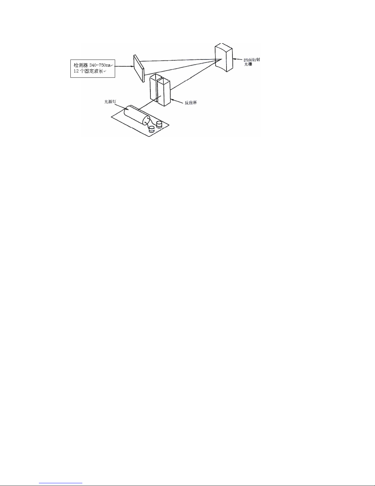
ii. Optical measurement movement sequence
Photometry in the entire process is adopted. In 13-minute reaction time, the continuous
determination of the absorbance of reaction solution is carried out. Reaction disk rotates 1 plus 2
pitches, about 15 seconds, absorbance values are measured out when the 120 reaction cups passing
optical axis of the photometer one by one.
Each reaction Cup in 3-minute reaction time was measured 12 times (12photometric points),
4-minute reaction time was measured 16 times (16 photometric points), 5-minute reaction time
was measured 20 times (20 photometric points), 10-minute reaction time was measured 40 times
(40 photometric points), 13-minute reaction time was measured 49 times (49 photometric
points).
Light starting from the light source was focused by the lens, and passed the reaction cup first, and
then was disparted by concave grating. After spectrophotometry, each wavelength were received
by 12 fixed photoelectric sensorssimultaneously, and were amplified 12 amplifiers, after Log
transformation to derive the rate of change of absorbance or absorbance. When dual-wavelength
testing is used, the concentration value is calculated by the difference of the main and
sub-wavelength absorbance or that of absorbance change rate, and therefore dual-wavelength
testing can not only compensate the blood lipid, hemolytic, jaundice sample test, but also
compensate on the result impacted by voltage changes, so that measurement is more accurate,
more stable.
DC E
Reaction disk rotate direction
GH
A B F
Test cell blank for 3 times(1 stop,2 pass)
20
Table of contents
Popular Laboratory Equipment manuals by other brands


logos biosystems
logos biosystems LUNA FX7 Series user manual

cytiva
cytiva ReadyToProcess Mixer 20/50 operating instructions

Benchmark
Benchmark R4040 Operation manual

Korona
Korona 1000 installation manual

Iconic
Iconic VF1 instruction manual

Markes International
Markes International Kori-xr installation manual

VWR International
VWR International 1915A-2 Installation and operation manual

Teledyne
Teledyne ACCQPrep AI 5 instruction sheet

Agilent Technologies
Agilent Technologies 8860 Site preparation guide

Metrohm
Metrohm 761 SD Compact IC Instructions for use

Accuris
Accuris MyGel Mini operating manual

Controls
Controls 58-C0181/DGT instruction manual